Rehau NEA Smart Base Station 24 V User manual

NEA SMART BASE STATION 24 V (WIRED)
Installation Instructions

CONTENTS
1 Safety 3
1.1 Used symbols and important safety instructions 3
1.2 Intended use 3
1.3 General safety warnings 3
1.4 Requirements with regard to personnel 3
1.5 Restrictions regarding use of product 3
1.6 Compliance 3
2 Versions 4
2.1 Box contents 4
2.2 Indicators and operating buttons 4
2.3 Connections 5
2.4 Technical data 5
3 Installation 6
3.1 Installation 6
3.2 Electrical connection 6
3.2.1 External change-over signal 7
3.2.2 Pump/boiler/chiller 7
3.2.3 Optional dew point sensor 7
3.2.4 Pilot function for change-over heating/cooling 7
3.2.5 External timer 8
3.2.6 Room BUS 8
3.2.7 System BUS 8
3.2.8 Use of high temperature limiter 8
3.2.9 Ethernet connection 9
4 Commissioning 10
4.1 First commissioning 10
4.2 Connecting (pairing) / separating base stations 10
4.3 Allocation of a room control unit to a heating zone (pairing)11
4.4 Perform connection test 11
4.5 System configuration 11
4.5.1 System configuration with microSD card 11
4.5.2 Configuration with Nea Smart room control unit D 11
4.6 Resetting the factory settings 12
5 Exercise functions and safe mode 14
5.1 Exercise functions 14
5.1.1 Pump exercise 14
5.1.2 Valve exercise function 14
5.1.3 Frost protection 14
5.1.4 Dew point monitoring 14
5.1.5 High temperature limiter 14
5.2 Safe mode 14
6 Troubleshooting and cleaning 15
6.1 Error messages and error handling 15
6.2 Fuse change 16
6.3 Cleaning 16
7 Decommissioning 17
7.1 Decommissioning 17
7.2 Disposal 17
More information on the NEA Smart control system and all
documentation available for download can be found at
www.rehau.uk/neafamily
2

1 SAFETY
1.1 Used symbols and important safety instructions
Electrical voltage! Danger to life! Safety instructions are
marked with this symbol.
Note
1.2 Intended use
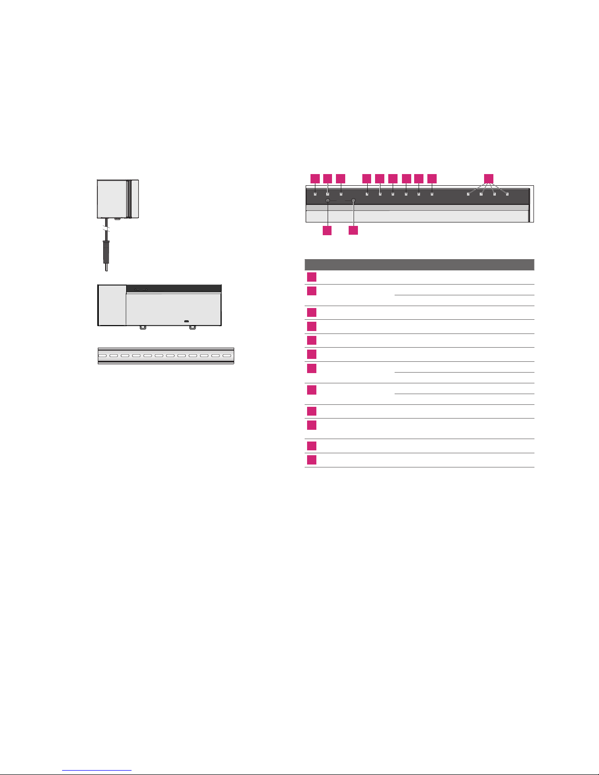
The NEA Smart base station 24 V is intended
- for a single room regulation system with a maximum of 8 zones for
heating and cooling systems,
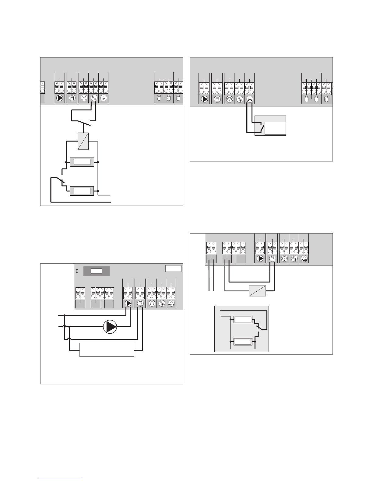
- for the connection of a maximum of 12 actuators UNI 24 V and any
combination of 8 NEA Smart R room control units, a pump, a CO
signalling unit, a humidity sensor with potential-free contact as well
as an external timer.
- for a fixed installation.
Every other use outside its intended use, the manufacturer cannot be
held liable for.
Modifications and conversions are expressively forbidden and lead to
dangers the manufacturer cannot be held liable for.
1.3 General safety warnings
Electrical voltage! Danger to life! The base station is live.
- Prior to opening always disconnect from the mains and
secure in such a way that it cannot accidentally be switched on.
- Disconnect all external voltages connected to the unit, e.g. at the
pump and the boiler contacts and ensure these cannot accidentally
be switched live.
Emergency
In case of emergency, disconnect the complete control system from
the mains.
Retain this manual and provide it to future owners.
1.4 Requirements with regard to personnel
Authorised specialists
The electrical installations must be performed according to the current
VDE regulations as well as according to the regulations of your local
electric power utility company. These instructions are intended for use
by a qualified person who is holding an ocial certificate in one of
the following professions: electrician or electronics engineer (accord-
ing to the profession designations ocially announced in the Federal
Republic of Germany, as well as according to comparable professions
within the European Community Law).
1.5 Restrictions regarding use of product
This base station is not intended to be used by people (including
children) with restricted physical, sensory or mental skills except if
they are supervised by a person responsible for their safety or have
received instructions on how to use this base station.
Children should be supervised in order to ensure that they do not play
with the device.
1.6 Compliance
This product is labelled with the CE Marking and therefore complies-
with the requirements from the following guidelines:
- 2004/108/EG with amendments “Council Directive on the approxi-
mation of the laws of the Member States relating to Electromagnetic
Compatibility”
- 2006/95/EG with amendments “Council for Coordination of the
Regulations of EU Member Countries regarding the electrical
equipment for use within certain voltage limits”
Increased protection requirements may exist for the overall installation,
the compliance of which is the responsibility of the installer.
3

2 VERSIONS
2.1 Box contents
1 x
1 x
1234
Power
rmBUS
Error
syBUS
Fuse Pump Boiler Cool
H% Master NO
Pairing
1 x
Fig. 2-1 Box contents
2.2 Indicators and operating buttons
1234
Power
rmBUS
Error
syBUS
Fuse Pump Boiler Cool
H% Master NO
Pairing
4 5 1098761 2 3
12 11
Fig. 2-2 Indicators and operating buttons
No. Designation LED Status Function
1Fuse red
permanent on
Fuse has blown
2syBUS
yellow
permanent on
Shows syBUS activity
Flashing Writing access on microSD-card
3Error red
permanent on
High temperature limiter active
4Power green
permanent on
Base station ready
5Pump green
permanent on
Pump output active
6Boiler green
permanent on
Lightsupwhenboileroutputisactiveiftheboilerrelayisusedforboilercontrol
7Cool H% blue
permanent on
Cooling mode active
Flashing Condensation detected
8Master
yellow
permanent on
Base station is defined as master
Flashing Base station is defined as slave
9NO
yellow
permanent on
Installation is configured for NO actuators (normally open)
10 Heating zones
1 - x
green
Shows the respective status of the heating/cooling zones
11 rmBUS button - Button for the rmBUS functionality
12 syBUS button - Button for the syBUS functionality
Tab. 2-1 Indicators and operating buttons
4

2.3 Connections
HZ 5 HZ 6 HZ 7 HZ 8 HZ 9 HZ 10 HZ 11 HZ 12
pump
1 2
boiler
1 2
ECO
1 2
CO
1 2
H %
1 2
HZ 1 HZ 2 HZ 3 HZ 4
1 1 1 11 12 2 2 22 2 1 1 1 11 12 2 2 22 2 1 1 1 11 12 2 2 22 2
L1‘
TB
L2‘
L1 L2
T2A
3 4 9
8765
24 V
1 2
HZ 5 HZ 6 HZ 7 HZ 8 HZ 9 HZ 10 HZ 11 HZ 12
pump
1 2
boiler
1 2
ECO
1 2
CO
1 2
H %
1 2
HZ 1 HZ 2 HZ 3 HZ 4
111111222222 111111222222 11111122222 2
L1‘
TB
L2‘
L1 L2
T2A
HZ 5 HZ 6 HZ 7 HZ 8 HZ 9 HZ 10 HZ 11 HZ 12
pump
1 2
boiler
1 2
ECO
1 2
CO
1 2
H %
1 2
HZ 1 HZ 2 HZ 3 HZ 4
11111122222 2
111111222222 11111122222 2
N
N
L L TB
T4AH
System BUS
B GND24V A
24 V 230 V
16 1715
21 3 4 5 6 7 8 9 10 11 12 1413
11 12
10
Fig. 2-3 Connections
No. Terminals Function
1Mains transformer Terminal for system transformer
2Output 24 V Output for the supply of e.g. high temperature limiter (to be provided by others)
3High temperature limiter Terminals for connecting high temperature limiter for protecting sensitive surfaces, to be provided by others (optional)
4Pump Terminal to switch pump
5Boiler Terminal to switch boiler or valves in case of CO mode
6ECO Potential-free input for external timer
7Change over Potential-free input (according to SELV) for external change-over signal
8Dew point sensor Potential-free input (according to SELV) for dew point sensor
9Actuators 12 connections for thermal actuators UNI 24 V
10 RJ45 connection Ethernet interface for the integration of the base station into the home network
11 RJ12 connection Connection for active antenna
12 microSD card slot Used for updating firmware and individual system settings.
Tab. 2-2 Connections
2.4 Technical data
NEA Smart Base Station 24 V
Ethernet x
Number of heating zones 8
Number of actuators 4x2 + 4x1
Max. nominal load of all actuators 24 W
Switching power per heating zone max. 1 A
Pump output 8 Amp resistive, inductive max. 200VA
Operating voltage 24 V / ±20%
Mains connection System transformer with mains plug
Power consumption (without pump) 50 W (limited by the system transformer)
Power consumption in idle operation/with transformer 1.1 W / 1.4 W
Protection class II
Protection degree/overvoltage category IP20 / III
Fuse 5 x 20 mm, T2A
Ambient temperature 0 °C – 60 °C
Storage temperature -25 °C to +70 °C
Relative Humidity 5% - 80%, not condensing
Dimensions 370 x 52 x 75 mm
Material PC+ABS
Control accuracy of set point ±1 K
Hunting ±0.2 K
Max. line length 500 m
rmBUS connection polarity reversal protected
Tab. 2-3 Technical data
5

3 INSTALLATION
3.1 Installation
Electrical voltage! Danger to life!
Only carry out installation work with all power disconnected
Installation
24 V
24 V
Fig. 3-1 Installation
3.2 Electrical connection
Electrical voltage! Danger to life!
Only carry out installation work with all power disconnected
The wiring of the control system depends on many factors and must
be planned and carried out carefully by the installer. The following
cable sizes are compatible with the terminals:
- solid cable: 0.5 – 1.5mm²
- multiple stranded cable: 1.0 – 1.5mm²
- 8 - 9mm insulation stripped o the cable
- Actuators with factory-fitted cable sleeves can be used.
Both L1/L1' terminals share a rail and both L2/L2' terminals
share a rail.
HZ 5 HZ 6 HZ 7 HZ 8 HZ 9 HZ 10 HZ 11 HZ 12
pump
1 2
boiler
1 2
ECO
1 2
CO
1 2
H %
1 2
HZ 1 HZ 2 HZ 3 HZ 4
1 1 1 11 12 2 2 22 2 1 1 1 11 12 2 2 22 2 1 1 1 11 12 2 2 22 2
L1‘
TB
L2‘
L1 L2
T2A
L1 L2
24 V
Fig. 3-2 Electrical connection
12
34
56
6

3.2.1 External change-over signal
HZ 5 HZ 6 HZ 7 HZ 8 HZ 9 HZ 10 HZ 11 HZ 12
pump
1 2
boiler
1 2
ECO
1 2
CO
1 2
H %
1 2
HZ 1
HZ 2 HZ 3 HZ 4
111111222222 111111222222 111111222222
N
N
LL
TB
T4AH
N
L
Cooling
Heating
Fig. 3-3 Terminal change-over signal
If an external change-over signal is used, the overall installation
switches accordingly between heating and cooling.
3.2.2 Pump/boiler/chiller
HZ 5 HZ 6 HZ 7 HZ 8 HZ 9 HZ 10 HZ 11 HZ 12
pump
1 2
boiler
1 2
ECO
1 2
CO
1 2
H %
1 2
HZ 1 HZ 2 HZ 3 HZ 4
111111222222 111111222222 111111222222
L1‘
TB
L2‘
L1 L2
T2A
N
L
Boiler
24 V
Fig. 3-4 Terminal for pump and boiler
The boiler terminal switches a boiler or chiller. Additionally, a pump
can be supplied directly with power and switched.
The use of a relay to switch a pump is recommended.
3.2.3 Optional dew point sensor
HZ 5 HZ 6 HZ 7 HZ 8 HZ 9 HZ 10 HZ 11 HZ 12
pump
1 2
boiler
1 2
ECO
1 2
CO
1 2
H %
1 2
HZ 1
HZ 2 HZ 3 HZ 4
111111222222 111111222222 111111222222
N
N
LLTB
T4AH
Umschalten der Anlage auf Kühlen durch Bedienung am RBG
H
N
L
Dew point
sensor
Fig. 3-5 Terminal for dew point sensor
Dew point sensors (to be provided by others) are used to prevent
condensation when in cooling mode.
The dew point alarm is triggered when the contact of the dew point
sensor is closed.
3.2.4 Pilot function for change-over heating/cooling
HZ 5 HZ 6 HZ 7 HZ 8 HZ 9 HZ 10 HZ 11 HZ 12
pump
1 2
boiler
1 2
ECO
1 2
CO
1 2
H %
1 2
HZ 1 HZ 2 HZ 3 HZ 4
111111222222 111111222222 111111222222
L1‘
TB
L2‘
L1 L2
T2A
L1
L2
N
L
Heating
Cooling
Fig. 3-6 Usage of the "Boiler" output as a pilot signal for change over
If no external change-over signal is available, the internal pilot function
of the base station can be used for switching the overall installation
between the operating modes Heating and Cooling. A relay used by
the base station for switching over is used for this.
7

3.2.5 External timer
HZ 5 HZ 6 HZ 7 HZ 8 HZ 9 HZ 10 HZ 11 HZ 12
pump
1 2
boiler
1 2
ECO
1 2
CO
1 2
H %
1 2
HZ 1 HZ 2 HZ 3 HZ 4
111111222222 111111222222 111111222222
L1‘
TB
L2‘
L1 L2
T2A
N
L
Fig. 3-7 Connection of an external timer
The base station is equipped with an ECO input for connecting an
external timer in this case the timers of the NEA Smart room control
unit D are not used. When the input is activated by the external timer,
the heating zones are switched into set back.
3.2.6 Room BUS
HZ 5 HZ 6 HZ 7 HZ 8 HZ 9 HZ 10 HZ 11 HZ 12
pump
1 2
boiler
1 2
ECO
1 2
CO
1 2
H %
1 2
HZ 1 HZ 2 HZ 3 HZ 4
1 1 1 11 12 2 2 22 2 1 1 1 11 12 2 2 22 2 1 1 1 11 12 2 2 22 2
N
N
L L TB
T4AH
System BUS
B GND
24V A
1 2
Room BUS
rmBUS
1 2
System BUS
B GND
24V A
System BUS
B GND
24V A
1
7
Fig. 3-8 Connection of Nea Smart room control units with base station Nea Smart
Eight room control units can be connected to the Room Bus (rmBUS).
The connection of the room control units is protected against polarity
reversal and can be executed in the topologies “line”, “tree”, or “star”.
Ideally standard beldon cable 0.8mm, two pair or similiar, should be
used. However, it is also possible to use an existing cable with at least
2 wires. The country-specific standards and regulations must always
be observed, however!
3.2.7 System BUS
HZ 5 HZ 6 HZ 7 HZ 8 HZ 9 HZ 10 HZ 11 HZ 12
pump
1 2
boiler
1 2
ECO
1 2
CO
1 2
H %
1 2
HZ 1 HZ 2 HZ 3 HZ 4
1 1 1 11 12 2 2 22 2 1
1 1 11 12 2 2 22 2 1 1 1 11 12 2 2 22 2
N
N
L L TB
T4AH
System BUS
B GND
24V A
System BUS
B GND
24V A
System BUS
B GND
24V A
1
7
Fig. 3-9 Base station connection via system BUS
Cable to be used: Standard beldon cable 0.8mm2two pair or
similiar.
Connect the shield to device earth (Gnd) on both sides!
A maximum of seven base stations can be interconnected via the
system BUS (syBUS) in order to exchange global system parameters.
After completing the wiring, the base stations must be paired – see
section 4.2. For cable sizes <6 mm, a strain relief is necessary (to be
provided by others).
3.2.8 Use of high temperature limiter
HZ 5 HZ 6 HZ 7 HZ 8 HZ 9 HZ 10 HZ 11 HZ 12
pump
1 2
boiler
1 2
ECO
1 2
CO
1 2
H %
1 2
HZ 1 HZ 2 HZ 3 HZ 4
111111222222 111111222222 111111222222
L1‘
TB
L2‘
L1 L2
T2A
N
L
1
Fig. 3-10 Terminal for high temperature limiter
Connecting a high temperature limiter (1) (supplied by others). When
triggered this input cuts the power to the pump and switches the input
TB if any excessive flow temperatures into the floor heating are
detected. If the TB input is switched, the base station automatically
closes all actuators.
8

3.2.9 Ethernet connection
The NEA Smart base station 24 V is equipped with a RJ45 interface
and an integrated web server for the control and configuration of the
system via PC/laptop and over the Internet.
- Integration of the base station into the network via network cable, or
direct connection to PC/laptop
Set-up in the home network:
- Open the router menu (see manual of the respective device) via the
address bar in the web browser (Internet Explorer, Firefox, …).
- Open an overview of all devices in the network.
- Compare to the MAC address (see type sign) in order to find out the
IP address allocated to the base station.
- Note the IP address of the base station and enter it into the address
bar of the web browser in order to open the web interface.
Direct connection to PC/laptop:
- Open the network settings in the PC/laptop and assign the IP ad-
dress 192.168.100.1 as well as
the subnet mask 255.255.0.0 manually to the PC.
- Access to the web interface can be gained by entering the IP ad-
dress 192.168.100.100 in the address bar of your web browser.
You can find further information on the set-up as well on worldwide
access via the Internet under www.rehau.uk/neafamily.
9

4 COMMISSIONING
4.1 First commissioning
The base station is in installation mode during the first 30 minutes
after switching on the mains power. The target and actual tempera-
tures are compared in this mode, all other functions are deactivated. If
the actual temperature is below the target temperature, the output
allocated to the respective room control unit is activated at the base
station. In this initial time all signals are activated instantly making it
possible to check the correct pairing of room control units and heating
zones.
- Switch on the mains power.
- The base station is in installation mode for 30 minutes.
- If the base station is configured for NC (normally closed) actuators,
all heating zones are activated for 7 minutes in order to unlock the
first-open function of the NC actuators.
- The power LED (operation display) lights up permanently.
4.2 Connecting (pairing) / separating base stations
If several base stations are used in one heating system, a maximum of
seven units can be connected with each other (paired) for the
exchange of global system parameters via system bus (syBUS).
Communication is done according to the master/slave principle.
Requirements and status messages are exchanged between the base
stations. The master base station centrally controls the directly
connected functions/components:
- CO input/output (if the pilot function is activated)
- Boiler output
- Pump output
1
2
3
4
5
6
7
Slave
Slave
Master
Fig. 4-1 System with multiple base station
The base station to which the components are connected must
be configured as master. Further base stations can only be
paired with the master.
The pairing of base stations is done as follows:
1. Press the syBUS button of the base station to be configured as
master for three seconds in order to start the pairing mode.
- The LED “syBUS” flashes.
- For three minutes, the pairing mode is ready to receive the
pairing signal of another base station.
2. Press the syBUS button of the base station to be configured as
slave two times consecutively for one second, in order pair it with
the master.
- The paring mode ends automatically after the process has
finished.
- The LED “Master” lights up permanently at the master base
station.
- The LED “Master” flashes if the base station has been
configured as slave.
3. Repeat the process for paring another base station.
Disconnecting a base station is done as follows:
4. Press the syBUS button of the base station to be separated for
three seconds in order to start the pairing mode.
- The LED “syBUS” flashes.
5. Press the syBUS button again for approx. 10 seconds.
- The base resets and the LED "Master" is o.
10

4.3 Allocation of a room control unit to a heating zone
(pairing)
1. Press the rmBUS button of the base station for three seconds in
order to start the pairing mode.
- The LED “Heating zone1” flashes.
2. Select the desired heating zone by pressing again briefly.
- For three minutes, the selected heating zone is ready to receive
the pairing signal of a room control unit.
3. Activate the pairing function at the room control unit (see NEA
Smart Room Control Unit Manual).
- The pairing mode ends automatically after establishing a
successful connection.
- The LED of the heating zone previously selected will light up for
1 minute.
4. Repeat the process for allocating more room control units.
One Room Control Unit can be allocated to various heating
zones. The allocation of several room control units to one zone
is not possible.
4.4 Connection test
The connection test can be used to test the communication between
the base station and the room control unit.
The base station must not be in pairing mode.
1. Start the connection test on the room control unit.
- Press the control knob for approx. 3 secs. in order to activate
pairing function (the display shows “Set”). At the base station,
the heating zone connected to this room control unit changes
status for 1 minute, in other words switches on or o depend-
ing on the previous operating status.
- The heating zone allocated to the room control unit is activated
for one minute and is switched o or on depending on its
current operating status.
2. If there is no activation, the signal is interrupted. Check
- whether the room control unit is paired with the base station
- whether all connections have full contact
- whether the communication bus wiring is not damaged.
4.5 System configuration
The base station is configured either via microSD card, the base
station web interface or the service level on the Nea Smart room
control unit D.
4.5.1 System configuration with microSD card
Individual settings can be made via the EZR Manager SD Card under
www.ezr-home.de and transferred to the base station via the
microSD card. As of software version 01.70, the base station accepts
microSD cards >2 GB in the formats FAT16 or FAT32.
1. Open www.ezr-home.de via the web browser on your PC, select
EZR Manager SD Card and follow the instructions online.
2. Insert the microSD card with the updated data into the base
station.
- The transfer process will start automatically and copy the
updated data into the base station.
- The LED “syBUS” flashes during the transfer process.
- After a successful data transmission, the LED “syBUS” stops
flashing.
4.5.2 Configuration with Nea Smart room control unit D
The Service level of the Nea Smart room control unit D is protected
with a PIN code and may only be used by authorized specialists.
Faulty configuration leads to errors and damages the
installations.
1. Press the control knob.
2. Select the menu “Service Level” and confirm by pressing.
3. Enter the 4-digit PIN (standard: 1314) by rotating and pressing.
4. Select parameters (PAr) by pressing again and enter the number
code of the desired parameter (see following table).
5. Change parameters as required and confirm by pressing.
11

No. Parameters Description Default Settings Unit
010 Used heating system
Adjustable per heating zone: Floor heating (FBH) standard / FBH low energy / radiator / convector passive / convector active
1 FBH St.=0
FBH NE=1
RAD=2
KON pas.=3
KON act.=4
020 Deactivate heating/cooling
Deactivating the switching outputs depending on the selected operating mode (heating/cooling)
0 normal=0
Heating deactivated=1
Cooling deactivated=2
030 Tamper Proof function
(child safety lock)
Password required for deactivate the tamper proof function 0 Deactivated=0
Activated=1
031
Password for tamper proof function
Determine PIN if parameter 30 is set to active – 0000..9999
040
External sensor connected to the room control unit
Register an additional sensor for monitoring the floor temperature (FBH), the room temperature or the dew point
2 no sensor=0
Dew point sen.=1
Temp FBH=2
Temp room=3
050 Backlit
Adjustable per room control unit: Duration that the display continues to be lit after operation
15 0 ... 30 s
default 15 s
051 Brightness
Adjustable per room control unit: adjusts the brightness of the back light of the display
50 10 ... 100 %
default: 50 %
052 Contrast Adjustable per room control unit: Sets the display contrast. 3 0 ... 7
default: 3
060
Temperature calibration of actual values
A correction factor is applied to the actual temperature 0,0 -2.0...+2.0 K
in 0.1 increments
110
Control direction switched output
Change between NC and NO actuators (only globally) 0 NC=0 / NO=1
115 Use as setback input
Change-over between use of the ECO input for setback or holiday function of the room control unit.
The holiday function cannot be activated any longer via the room control unit if this parameter has been set to 1.
0 ECO=0
Holiday=1
120 Unit of temperature display Toggle the display between degree Celsius and degree Fahrenheit 0 °C=0
°F=1
Pump configuration
130 Pump output
Use the control of a local recirculation pump (in the heating circuit distributor) or a global recirculation pump (heating installation).
0 local=0
global=1
131 Pump type Selection of the used pump: Conventional Pump (KP) / High efficiency Pump (HP) 1 CP=0
HP=1
132 Pump delay Time delay between demand signal and acutal activation of pump. 4 min [min]
133 Pump overrun Time between closing of actuators and switching off pump. 2 min [min]
134
Control direction switched output
The control direction can be reversed if the pump relay is used as control output 0 normal=0
reversed=1
135 Minimum running time
The minimum running time indicates how long the HP must run until it may be switched off again.
30 min [min]
136 Minimum standstill time
High efficiency pump: The pump may only be switched off if a minimum standstill time can be ensured.
10 min [min]
Configuration of change-over functionality / boiler relay
140
Function of relay boiler / CO output
Selection whether the switching output shall serve for controlling a pump relay, or as CO pilot
0 Boiler=0
CO pilot=1
141 Boiler delay Boiler delay for conventional pump Pump 5 min [min]
142 Overrun Boiler overrun time for conventional pump Pump 1 min [min]
4.6 Resetting the factory settings
Attention! All user settings will be lost.
1. If present, remove the microSD Card from the base station and
delete the parameter file “params_usr.bin” using a PC.
2. Press the rmBUS button on the base station for three seconds in
order to start the pairing mode.
- The LED “Heating zone1” flashes.
3. Press the rmBUS button again for 15 seconds, until all heating
zone LED’s flash simultaneously, the LEDs then light up and then
go out.
Now the base station is reset to factory settings and behaves as it did
during the first commissioning (see section 4).
Previously allocated room control units must be paired again,
see section 4.3.
12

No. Parameters Description Default Settings Unit
143
Control direction switched output
If used as a control output the relay function can be reversed. 0 normal=0
reversed=1
160 Frost protection Activation of control outputs for Tactual <x °C 1 Deactivated=0
Activated=1
161
Minimum temperature in frost protection mode
Limit room temperature at which frost protection mode is activated 8 °C [°C]
170 Smart Start
Adaptive self learning of the temperature behaviour of each individual heating zones
0 Deactivated=0
Activated=1
Safe mode operation
180 Time until activated Delay until safe mode is activated 180 min [min]
181
PWM cycle duration in safe mode
Duration of a PWM cycle in safe mode 15 min [min]
182 Cycle duration PWM heating Control duration in heating operation 25 % [%]
183 Cycle duration PWM cooling Control duration in cooling operation 0% [%]
Valve exercise
190 Time until activated Running time since last activation 14 d [d]
191 Duration of valve exercise Duration of valve exercise (0= function deactivated) 5 min [min]
Pump exercise
200 Time until activated Running time since last activation 3 d [d]
201 Time until activated Activation duration (0 = function deactivated) 5 min [min]
210 First open function (FO) Activation of all actuator outputs in installation mode 10 min [min]
Off=0
220
Automatic switching between summer and winter time
If activated, time switching follows automatically the CET guidelines 1 Deactivated=0
Activated=1
230
Setback temperature differential
In case of activation of the setback via the external input 2 K [K]
Tab. 4-1 Parameters
13

5 EXERCISE FUNCTIONS AND SAFE MODE
5.1 Exercise functions
The base station is equipped with many exercise functions for avoiding
damage to the overall system.
5.1.1 Pump exercise
In order to avoid damage by prolonged standstill times, the pump is
regularly activated in pre-set intervals. The LED “pump” lights up
during these periods (see parameters 200/201).
5.1.2 Valve exercise function
During prolonged periods without valve activation (e. g. outside the
heating period) all heating zones with a paired room control unit are
regularly activated to prevent setting of the valves (see parameters
190/191).
5.1.3 Frost protection
Independent from the operating mode, every switched actuator output
has a frost protection. When the actual room temperature falls below
the preset minimum frost protection temperature, the corresponding
actuators are opened until the minimum frost protection temperature
is reached again in the room. The frost protection temperature can be
set via the microSD card, via the software surface of the Ethernet
variant or via the service level of the NEA Smart room display unit
(parameter 161).
5.1.4 Dew point monitoring
If the installation is equipped with a dew point sensor (provided by
others), the valves of all heating zones are closed if condensation is
detected in order to avoid damage due to moisture. The dew point
sensor input is only used during cooling operation.
The alarm is triggered when the contact is closed.
5.1.5 High temperature limiter
If an optional high temperature limiter is used, all valves are closed
when a preset temperature is exceeded in order to avoid damage to
sensitive floor coverings.
5.2 Safe mode
If the base station is unable to establish a connection to a room
control unit allocated to a heating zone for a preset time (parameter
180), the safe mode is activated automatically. In safe mode, the
switched outputs at the base station are activated with a modified
PWM cycle duration (parameter 181) independent from the heating
system in order to avoid complete cooling of the rooms (in heating
operation) or condensation (in cooling operation).
14

6 TROUBLESHOOTING AND CLEANING
6.1 Error messages and error handling
Signal code of the LEDs Meaning Handling
Fuse
01234
Duration in seconds Fuse defective Change the fuse
(see section 6.2)
Fuse
Error / Pump
01234
Duration in seconds
High temperature limiter active,
valves are closed
Thenormalcontroloperationisautomaticallyresumedwhenthetemperaturedropsagainbelowthe presetlimit
Pump
Error
“Cool H% “ (only cooling operation)
01234
Duration in seconds Condensation detected,
valves are closed
Thenormal controloperationis automaticallyresumed when no condensationis detected anymore.
Cool
Heating zone
01234
Duration in seconds Safe mode active
Check bus line for interruptions.
Carry out a connection test.
Replace a defective room control unit.
HZ
Tab. 6-1 Troubleshooting
LED o
LED on
1234
Power
rmBUS
Error
syBUS
Fuse Pump Boiler Cool
H% Master NO
Pairing
Fig. 6-1 Indicators and operating buttons
15

6.2 Fuse change
Electrical voltage! Danger to life!
The base station is live.
- Prior to opening always disconnect from the mains and secure in
such a way that it cannot accidentally be switched on.
- Prior to replacing the fuse and connecting the power again, always
check the wiring and connected components for any faults.
- Only use the specified fuse for this base station T2A, 5 x 20 mm.
23
4 5 6
Fig. 6-2 Changing the fuse
6.3 Cleaning
Only use a dry and solvent-free, soft cloth for cleaning.
1
16

7 DECOMMISSIONING
7.1 Decommissioning
Electrical voltage! Danger to life! The base station is live.
- Prior to opening always disconnect from the mains and
secure in such a way that it cannot accidentally be switched on.
- Disconnect all external voltages connected to the unit, e.g. at the
pump and the boiler contacts and ensure these cannot accidentally
be switched live.
7.2 Disposal
The base stations must not be disposed of with domestic
waste. The operator has the duty to dispose of the units
through appropriate collection points. The separate
collection and orderly disposal of all materials will help to
conserve natural resources and ensure a recycling in a manner that
protects human health and the environment. If you need information
about collection points for your devices, please contact your local
council or your local waste disposal services.
17

18
NOTES

19
NOTES

© REHAU Ltd
Subject to technical changes.
954621 EN 04.2016
Follow REHAU Underfloor:
UK HEAD OFFICE
Rehau Ltd, UK Head Oce, Hill Court, Walford, Ross-on-Wye, Herefordshire HR9 5QN Phone: 01989 762 600 Fax: 01989 762 601
UK & IRELAND SALES OFFICE
London, REHAU Ltd, The Building Centre, 25 Store Street, London WC1E 7BT Phone: 0207 580 6155 Fax: 0207 307 8595 Slough, Units 5 J & K, Langley Business Centre, Station
Road, Langley, Slough SL3 8DS Phone: 01753 588500 Fax: 01753 588501 Manchester, Brinell Drive, Irlam, Manchester M44 5BL Phone: 0161 777 7400 Fax: 0161 777 7401
Glasgow, Phoenix House, Phoenix Crescent, Strathclyde Business Park, Bellshill, North Lanarkshire ML4 3NJ Phone: 01698 503700 Fax: 01698 503701 Dublin, 9 St. Johns Court,
Business Park, Swords Road, Santry, Dublin 9 Phone: 00353 (0)1 8165020 Fax: 00353 (0)1 8165021
Our verbal and written application engineering advice is based upon experience and the best of our knowledge. However it is to be regarded as non-binding information.
Working conditions and use under conditions for which the product was not intended and over which we have no influence exclude any claim resulting from our information. We
recommend that a suitable check is made as to whether the REHAU product is suitable for the envisaged purpose. Application, use and processing of the products is carried out
beyond the scope of our control and are therefore carried out exclusively at your own responsibility. If liability should still apply, then this is restricted, in the case of all damage,
the value of the goods supplied by us and used by you.
Our warranty applies to the consistent quality of our products as per our specification and in accordance with our general terms and conditions of delivery and payment. This
document is protected by copyright. All rights based on this are reserved. No part of this publication may be translated, reproduced or transmitted in any form or by any similar
means, electronic or mechanical, photocopying, recording or otherwise, or stored in a data retrieval system.
www.rehau.uk/neafamily
Table of contents
Popular Network Router manuals by other brands

Moxa Technologies
Moxa Technologies EtherDevice EDR-G902 Hardware installation guide

HMS
HMS Anybus AWB5121 Startup guide

SEIKAKU TECHNICAL GROUP
SEIKAKU TECHNICAL GROUP RVA200 user manual

Tenda
Tenda D810R ADSL2+ user guide

Avaya
Avaya ERS 1600 Technical configuration guide

D-Link
D-Link DWP-1010KT Quick installation guide