REIGN XRE-100 User manual

WHAT’S INCLUDED
The REIGN XRE-100 Relay Extender is a revolutionary product that
will make any drycontact wireless with no programming or
configuration whatsoever - it literally is a plug and play device.
HOW IT WORKS...
Congratulations on your purchase of the Transmitter Solutions XRE-100 Relay Extender System. It has been
designed with state-of-the-art radio technology to extend relay closures, switches, indicators, sensors, and any
other simple ON/OFF status inputs and outputs through extreme obstruction and interference.
If you ordered your XRE-100s together, they are factory paired. All that is required to get up and running is 12-24
Volts AC/DC power and the DRY input closures you want to extend.
If you would like to survey the range capability before install, simply provide power to both units and press the
PROG/TEST button alternately on each unit. Successful transmission and reception will be indicated on the
transmit and receive LEDs on each unit as described below.
v. . .1
XRE–100
RELAY EXTENDER
There are two pieces that complete the XRE-100.
The Reign XRE-100 - Relay Extender kit includes 2- XRE-100 units. These units are interchangeable and can be
paired in the field.
Transmitter Solutions refers to the XRE-100 installed at the peripheral device as the Node and the XRE-100
installed at the primary unit the Hub. This is only important during technical support and the wiring diagram.
R E IGN wire l ess
t e chno l o g y

2
CONTENTS:
. . . . . ....... . . . . . . . . ... . . . .... . . .... . . . . . . . ........ . . . . ... . . . . . . . . .... . . . . . . .......
. . . . . . . ....... . . . ........ . . . . . . .... . . . . . ....... . . . . . . ...... . . .... . ........ . .
. . . ... . . . . . ....... . . . ........ . . . . . ....... . . . ........ . . . . . ..... . . ....
. . . . . . . . ....... . . . . . ...... . . . . ....... . . . . . . . .... . . . . ... . . . ... . . . . . . .......... . .... .
. . ... . . . ........ . . ....... . . . . ....... . . . . . ...... . . . . . ......... . ...
. . . ... . . . . . . . ... . . . .......... . . . . . ....... . . ....... . . . . . . ....... . . ... . . ..... . . .... . .
. . . ... . . . . ........ . . ... . . . . ... . . . . . . .... . . . ... . . . . . . . . ....... . . . . . ............
TROUBLESHOOTING.... . . ......... . . . . ... . . . . . . . . . . ... . . . . . . ... . . . . . . . . . . . ... . . . . . . ...........10
1.
. . . . . ... . . . . . . ... . . . . ... . . . . . . .... . . . ... . . . . . . . . ....... . . . . . ..............9
. . . . . . . . . . ... . . . . . . . . . . . . . . . . .... . . . . . . . . . . . . . . . . . .... . . . . .... . . . . 9

Power Input: 12-24 Volt AC/DC
Relays: 10A 250 VAC/ 28VDC
12V: 50mA (idle)
1A (transmit)
24V: 25mA (idle)
500ma (transmit)
Range: 1/2 mile (Through obstructions)
Relays: 10A 250 VAC/28VDC
Minimum / Maximum Temperature Range:
-40°F to 185°F(-40°Cto85°C)
SecurityEncryption: AES
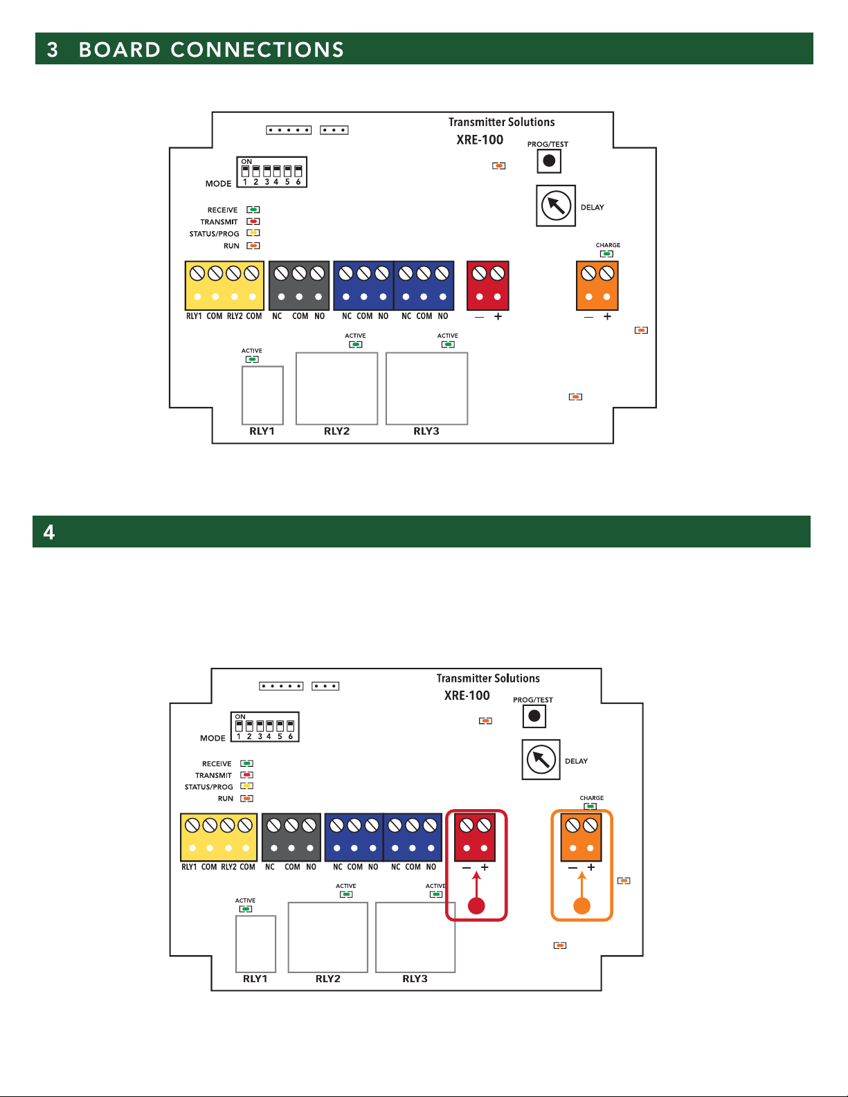
POWER INPUT:12 to 24 VOLTS AC/DC. - 1 AMP MinimumAlways follow polarity when DC
Power is used.
BATTERY INPUT:for 12 Volt Sealed Lead Acid (SLA) battery only.
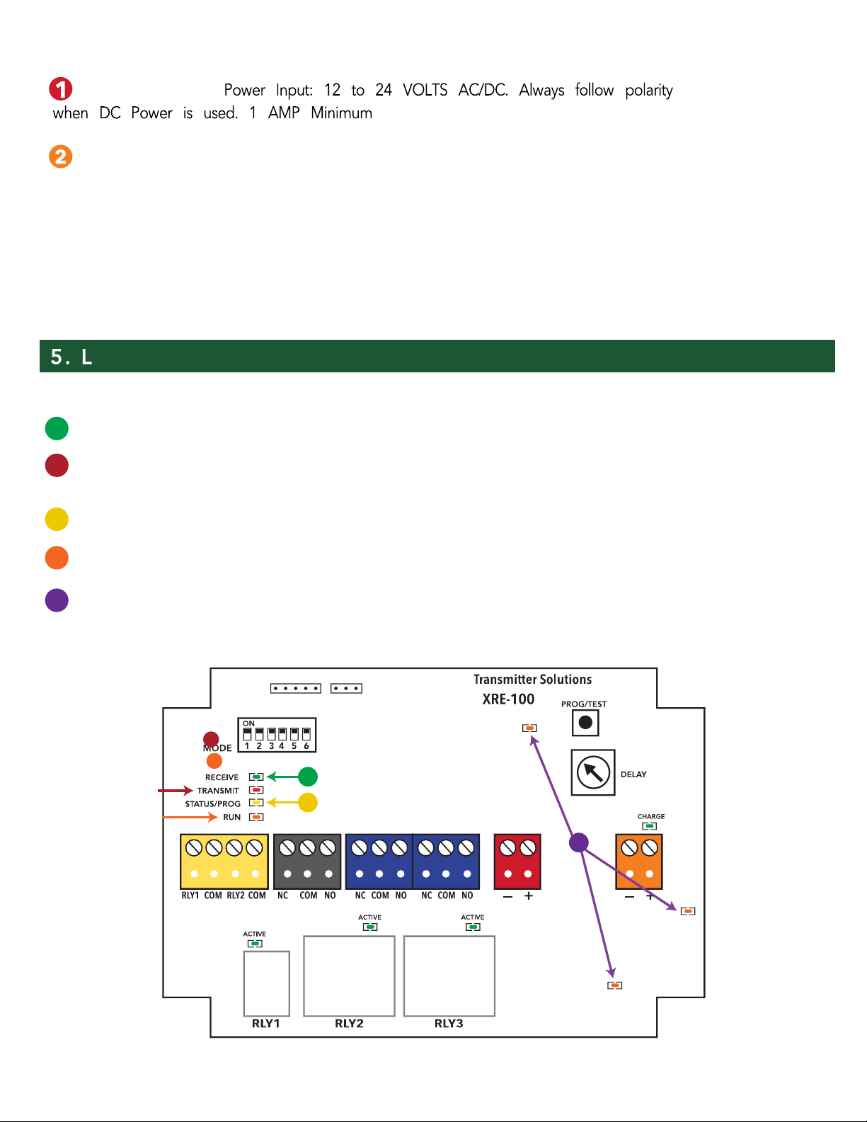
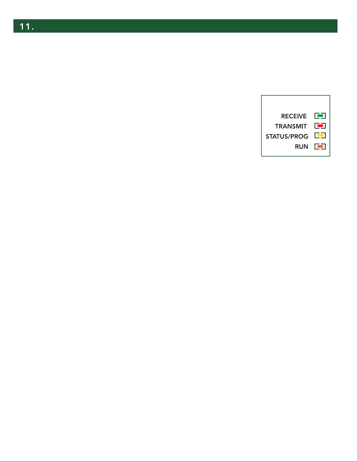
Solid GREEN LED indicates battery charging. Momentarily flashing GREENLED indicates battery is charged
and a trickle/conditioning chargeis occurring.
3
..
1.
FCC ID: 2ASPOXRE100A: This device complies with part 15 of the FCC rules. Operation is subject to the following
two conditions: (1) This device may not cause harmful interference, and (2) this device must accept any interfer-
ence received, including interference that may cause undesired operation.
IMPORTANT! Any changes or modifications not expressly approved by the party responsible for compliance could
void the user's authority to operate this equipment.
NOTE: This equipment has been tested and found to comply with the limits for a Class B digital device, pursuant to
part 15 of the FCC Rules. These limits are designed to provide reasonable protection against harmful interference in
a
residential installation. This equipment generates, uses and can radiate radio frequency energy and, if not installed
and used in accordance with the instructions, may cause harmful interference to radio communications. However,
there is no guarantee that interference will not occur in a particular installation. If this equipment does cause harmful
interference to radio or television reception, which can be determined by turning the equipment off and on, the user
is encouraged to try to correct the interference by one or more of the following measures:
• Reorient or relocate the receiving antenna.
• Increase the separation between the equipment and receiver.
• Connect the equipment into an outlet on a circuit different from that to which the receiver is connected.
• Consult the dealer or an experienced radio/ TV technician for help.
FCC Radiation Exposure Statement
This equipment complies with FCC radiation exposure limits set forth for an uncontrolled environment. This
equipment should be installed and operated with minimum distance 20cm between the radiator and your body.
This transmitter must not be co-located or operating in conjunction with any other antenna or transmitter.
The antennas used for this transmitter must be installed to provide a separation distance of at least 20 cm from all
persons and must not be co-located or operating in conjunction with any other antenna or transmitter.
FCC Caution: To assure continued compliance, any changes or modifications not expressly approved by the party
responsible for compliance could void the user's authority to operate this equipment.
(Example - use only shielded interface cables when connecting to computer or peripheral devices).

. POWER DETAILS
Each side of TheXRE-100(Hub and Node) need 1 amp of current draw totransmit at full power.
IMPORTANT - XRE REQUIRES AT LEAST 1AMP POWER SUPPLY
21
4
.

ED INDICATORS
STATUS LEDs:
RECEIVE - flashes GREEN momentarily when avalid radio transmission is received.
TRANSMIT - flashes RED momentarily when theunit transmits apacket as a result of an Relay Input change
event or handshake.
STATUS/ PROG- flashes yellow patterns indicating status of the unit: pairing, error, etc.
RUN- flashes ORANGE 1 secondON and 1 second OFF indicating themicroprocessor is running.
POWER LED - Glows solidorangewhen power is present. 5 volt relay supply, 3.3 volt logicsupply, and VPA
3.6volt power amplifier supply.
1
3
1
2
3
4
5
4
2
5
5
1POWER INPUT:
BATTERY INPUT:
BatteryInput: for 12 Volt Sealed Lead Acid (SLA) battery only.
Solid Green LED = Battery charging
Momentary Flashing LED =Battery is fully charged and atrickle/conditioning chargeis occurring

.RELAY DIAGRAM AND WIRING
–
RELAY INPUTS
Relay Inputs - The Reign XRE-100 comes with 2relay inputs. Connect DRY closure from devices relay to be
extended. A closure on RLY1 input will result in a closure on RLY1 (NC/COM/NO) of the paired XRE-100. A
closure on RLY2/COM input will result in a closure on RLY2 (NC/COM/NO output) of the paired XRE-100.
RELAY OUTPUTS
Relay Outputs- The ReignXRE-100 comes with 2-relay outputs. Each output follows RELAY INPUTS from
remote paired XRE-100. When RLY1 or RLY2 INPUTSare closed RLY1 and RLY2 OUTPUTS are energized and
connect NC/COM/NO respectively. This relay state is also indicated by the GREEN ACTIVELED above each
relay.
1
2
21
6

. ALERT RELAYS
ALERT INPUT (when DIP switch 2 is on)
ALERT RELAY OUTPUT
Both RELAY 1 andRELAY2 INPUTsaresupervised when DIPSWITCH 2 in ON.
Supervised inputs detect fault or tampering of inputs and send an ALERT RELAY
activation to the opposite unit (Typically from the Nodeunit to the Base unit).
Supervised inputs will detect an input shorted to ground (or each other) or an open
input(loose or cut wire). Connect the supplied 1K ohm and 2K ohm resistors across
the device to be monitored as shown. IMPORTANT: resistors must be connected at
the device to be monitored NOT AT THE XRE-100 RELAY INPUT.
When in Supervise Mode, unused inputs must be terminated withthe supplied 3K
ohm resistor. Simply insert the resistor into the Rx and COM pins on the desired
connector and tighten screw blocks.
If Supervised Inputs are not desired, simplyleave DIPSWITCH 2 OFF and wire your
contact directly acrossthe Rx and COM pins.
NOTE: Communication Loss - If the XRE-100 units stop communicating the Alert
Relay Output(Black relay) will trigger. Alerting on loss of communication between
devices.
1
2
2K OHM
3K OHM
3K OHM
1K OHM
BROWN
BLACK
RED
RED
BLACK
RED
ORANGE
BLACK
RED
GOLD
GOLD
GOLD
SUPERVISOR RESISTOR
COLOR CODES
Monitored
Contact
Unused Input
XRE-100
Customer
Wires
1K
2K
Detects: OPEN (cutwires) or,
SHORT (wire to each other or ground)
1. Supervise resistors (supplied) must be at con-
tact.
2. Associated DIPSWITCH SW2 must be ON
3. Connect contact directly, without resistors for
unsupervised inputs. SW5 and SW6 = OFF.
3K
7

DIPSWITCHES
MODE SWITCHES
SWITCH 1– PROG (PAIR) –Pairing mode when ON and Normaloperating mode when OFF
SWITCH 2– SUPERVISED INPUTS–Supervised inputs active when ON
SWITCH 3– COMMSLOSS BEACON –Pulses Alert Relay if ON, otherwiseRelay is steady on
SWITCH 4– Not used
SWITCH 5– Not used
SWITCH 6– Not used
RELAY OUTPUT SWITCH:
Relay Output Switch- not used in XRE-100 toXRE-100 Relay Extension operation.
PROGRAM/TESTBUTTON:
Program/Test Button- used with MODE SWITCH 1to fieldpair units as described above. Functions as a TEST
TRANSMIT button during normaloperation. When pressed, the XRE-100 willsend aradiotest packet and theRED
TRANSMIT LED will illuminate. If the paired XRE-100 is online, it will acknowledge with aradio test packet –
indicated by a momentary GREEN RECEIVE LED.
RELAY DELAY POTENTIOMETER:
Relay Delay Potentiometer: not used in XRE-100 to XRE-100Relay Extension operation.
13
4
1
2
3
4
8

. BATTERY BACKUP
12 Volt Sealed Lead Acid (SLA) battery only. Solid GREENLED indicates battery charging. Momentarily
flashing GREEN LED indicates battery is chargedanda trickle/conditioning chargeis occurring.
Flip Dipswitch 1to ON on both units.
Press the PROG/TEST button on either unit
NOTE: Observe the STATUS/PROG LED flashing.
Flip Dipswitch 1to OFFon both units
Press PROG/TEST and observe TRANSMIT and RECEIVE LEDs operating normally.
Pairing procedure overwrites any previous units. For example, if replacingaunitsimply follow the above
procedure with the existingandreplacement unit.
. PAIRING IN THE FIELD
PAIRING
1
2
3
4
1
2
4
3
UNIT 1
UNIT 2
1
3
9

XRE-100 units are not communicating:
1-Check the Run LED. Normal operation will be orangeLED flashing once asecond.
2-Press the red program button on the XRE-100. When pressed, the XRE-100 willsenda radiotest packet and the
RED TRANSMIT LED will illuminate. If thepaired XRE-100 is online, it will acknowledge with aradio test packet –
indicated by amomentary on the green receive LED.
If you do not see the transmit and receive LED lights activate:
1-Power cycle both the XRE units.
2 - Move the XRE-100 units to a higher location and avoid mounting on/in metal objects
If you are not getting the desired range between XRE-100 units:
1-Ensurethat the both devices are powered by their own dedicated power supply
2-Ensurethat 1 amp of power draw is available to each device during transmission
3-Movethe XRE-100 units to a higher location - and avoiding mounting in/on metal objects
TROUBLESHOOTING
XRE LED GUIDE
10

The warranty period of this product is 24 months, beginning from the manufacturing date. During this period, if the
product does not operate correctly, due to a defectivecomponent, the product will berepaired or replaced at thesole
discretion of Transmitter Solutions. This warranty does not extendto theproduct casing which can be damaged by
conditions outside of the control of Transmitter Solutions.
EXCEPT AS SET FORTH ABOVE, TRANSMITTER SOLUTIONS MAKES NO WARRANTIESREGARDING THE GOODS, EXPRESS OR IMPLIED,
INCLUDING WARRANTY OF MERCHANTABILITY OR WARRANTY OF FITNESS FOR APARTICULAR PURPOSE. BUYER MAKES NO RELIANCE ON
ANY REPRESENTATION OF TRANSMITTER SOLUTIONS, EXPRESS OR IMPLIED, WITH REGARD TO THE GOODS AND ACCEPTS THEM
“AS-IS/WHERE-IS”. TRANSMITTER SOLUTIONS SELLS THE GOODS TOBUYER ON CONDITION THAT TRANSMITTER SOLUTIONS WILL HAVE NO
LIABILITY OF ANY KIND ASARESULT OF THE SALE. BUYER AGREES THAT TRANSMITTER SOLUTIONS SHALL HAVE NO LIABILITY FOR
DAMAGESOF ANY KIND, WHETHER DIRECT, INCIDENTAL OR CONSEQUENTIAL DAMAGES, INCLUDING INJURIES TO PERSONS OR PROPER-
TY, TOBUYER, ITS EMPLOYEES OR AGENTS, AS A RESULT OF THE SALE. BUYER ALSO AGREES TO HOLD TRANSMITTER SOLUTIONS
HARMLESS FROM ANY CLAIMSBUYER, OR ANY THIRD PARTY, MAY HAVE AS A RESULT OF BUYER’S USE OR DISPOSAL OF THE GOODS.
BUYER HAS READ THIS DISCLAIMER AND AGREES WITH ITS TERMSIN CONSIDERATION OF RECEIVING THE GOODS.
WARRANTY
11

PH 866.975.0101 • FX 866.975.0404
www.transmittersolutions.com
Table of contents