Rekluse YXZ 1000 Operation manual

©2017 Rekluse Motor Sports
Rekluse Motor Sports, Inc.
customer[email protected]
INSTALLATION & USER’S
GUIDE
TorqDrive Clutch
YXZ 1000
Doc ID: 191-2870A
Revision: 110617

Pg. 2 Doc ID: 191-2870A
Doc Rev: 110617
Table of Contents
OVERVIEW ...................................................................................3
INSTALLATION TIPS....................................................................3
TOOLS...........................................................................................4
INCLUDED PARTS.......................................................................5
DISASSEMBLE CLUTCH..............................................................6
CLUTCH INSTALLATION .............................................................8
INSTALL THE PRESSURE PLATE.............................................11
BREAK-IN....................................................................................15
SHIFTING AND OPERATION.....................................................15
MAINTENANCE...........................................................................15
DISK EXAMPLES FOR INSPECTION........................................17
NEED ADDITIONAL HELP?........................................................18

Doc ID: 191-2870A
Doc Rev: 110617
Pg. 3
OVERVIEW
This kit replaces many of the OE (Original Equipment) clutch
parts. The following is a summary of what is replaced:
•This kit will replace all the OE frictions and drive plates with a
Rekluse thin friction clutch pack.
•The OE pressure plate is replaced with a Rekluse pressure
plate.
•The OE pressure plate springs are replaced with high quality
Rekluse springs.
INSTALLATION TIPS
•Read the separate included Safety
Information document before
operating the vehicle with the
product installed.
•Read this entire document before
performing any steps.
•If you install this product for a customer or another person,
instruct them to read the Safety Information document and
the Installation and User Guide before operating the bike
with the product.
•Protect eyes and skin – wear safety glasses and work gloves.
•Use the torque values listed in the instructions. Otherwise,
use the torque specifications found in your OE service
manual.
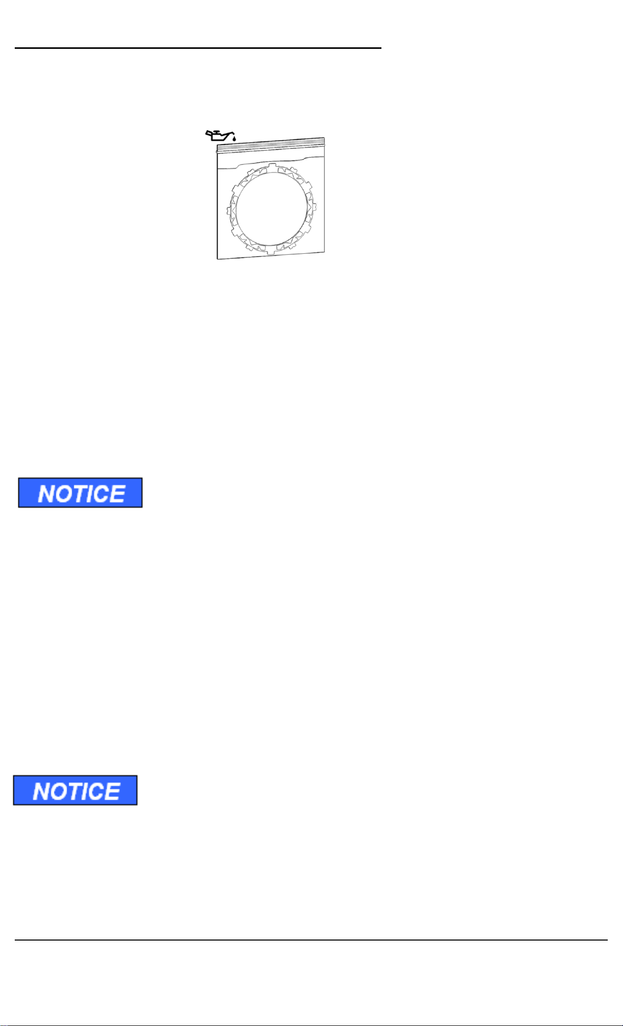
•Use clean, quality oil with the JASO-MA or JASO-MA2
certification for motorcycles for best performance.

Pg. 4 Doc ID: 191-2870A
Doc Rev: 110617
TOOLS
Flashlight Magnet Stick
(X2) Metric
Wrench Set Torque
Wrench
Pick 5 mm Hex key
Metric Socket
Set
5 mm

Doc ID: 191-2870A
Doc Rev: 110617
Pg. 5
INCLUDED PARTS
Item
Description
Qty.
16 Lining Plate 1
31 Spring Sleeve 6
47 Fastener 6
60.1 / 60.2 Pressure Plate Springs Blue and Red 6
68.1 Drive Plate 14
68.2 Drive Plate – Skip tooth 1
69 TorqDrive Friction Disk 16
70 Basket Sleeves 12
78 Pressure Plate Assembly 1
Not Shown Pressure Plate Springs Gold 6
Not Shown Clutch cover gasket 1
Visit www.rekluse.com/support for
a full parts fiche illustration and part numbers.

Pg. 6 Doc ID: 191-2870A
Doc Rev: 110617
DISASSEMBLE CLUTCH
1. Soak the included friction disks in engine oil for at least 5
minutes. Make sure the friction disks are coated on both
sides.
2. Remove the driver seat, passenger seat and center console
body panels to access to the clutch cover.
3. Remove the clutch cover bolts and clutch cover. Refer to
vehicle service manual for instructions.
•It is not necessary to drain the oil however it is
recommended to change the oil after clutch break-in.
The bolts along the bottom of the clutch cover also have copper
crush washers. Be sure to reinstall the crush washers with the
bolts in the proper locations.
4. Remove the following OE parts. See picture for reference.
•Lower clutch pack with
damper springs
•Wire circlip
•Upper clutch pack
•Pressure plate
•Spring seat
•Spring
•Spring retainer
•Bolts
To remove the lower clutch pack, you will need to remove the
wire circlip from the inner hub. To remove the wire circlip, use
needle nose pliers and/or picks. The wire circlip WILL NOT be re-
used.

Doc ID: 191-2870A
Doc Rev: 110617
Pg. 7
5. Ensure all parts of the lower clutch pack are removed. The
push rod, inner hub, and basket do not need to be removed.

Pg. 8 Doc ID: 191-2870A
Doc Rev: 110617
6. Use magnets to remove damper spring and damper spring
seat from the bottom of the lower clutch pack.
CLUTCH INSTALLATION
Clutch Pack Cutaway Overview

Doc ID: 191-2870A
Doc Rev: 110617
Pg. 9
1. Inspect the clutch basket for damper/cushion play or notching.
Do not install sleeves or use product with a notched basket.
Notched basket tang faces or worn dampers can cause the
sleeves to break.
Failure to inspect the basket and replace if necessary could
result in death, serious injury, and/or property damage.
2. Install all of the Rekluse basket sleeves into the basket slots.
Make sure the bottom of the sleeve is facing down, and the
long sleeve tabs sit against the inside of the basket. See
pictures for reference.
Install all the
basket sleeves

Pg. 10 Doc ID: 191-2870A
Doc Rev: 110617
3. Ensure damper spring, damper spring seat, and bottom narrow
friction were removed. The clutch will not install properly if
these parts are still in place.
4. Install a friction disk into the clutch basket, then install a steel
drive plate. Some friction disks are marked with a small colored
dot. This mark is used for processing and can be ignored.
Some OE basket have “half slots” at the top of the basket tangs.
Rekluse products require the entire clutch pack be installed into
the MAIN (deeper) basket slots. (These slots are lined with the
basket sleeves.) See the following picture for reference.
5. Continue to alternate 14 friction disks and 13 steel drive plates
into the clutch. You will end with a friction disk on top and have
1 friction disk left over.

Doc ID: 191-2870A
Doc Rev: 110617
Pg. 11
INSTALL THE PRESSURE PLATE
The pressure plate requires two different plates be correctly
aligned in order for the clutch to function properly.
1.Install the skip tooth steel drive plate onto the clutch pack by
aligning 2 of the plate’s teeth in the CENTER of any 2 bolt
posts on the inner hub.
2. Install the last Rekluse friction disk on top of the skip tooth
drive plate. Be sure to line up the tabs on the friction disk with
the rest of the pack in the main basket slots.
Rekluse friction
disk
Skip tooth
drive plate

Pg. 12 Doc ID: 191-2870A
Doc Rev: 110617
3. Turn the pressure plate over and place a thin layer of oil
between the lining plate and the pressure plate. This will help
hold the lining plate in place while installing the pressure plate
over the clutch pack.
4. Align the teeth of the lining plate with the taller slots in the
pressure plate, then drop the lining plate into the slots. The
lining plate will sit flush with the pressure plate.
5. Turn the pressure plate assembly over and locate the small
hole directly above the part number.
This will be a reference point for lining up
the pressure plate. You can mark this point
with a marker as well for ease of installation.
Lining
plate
Pressure plate

Doc ID: 191-2870A
Doc Rev: 110617
Pg. 13
6. Align the small hole on the pressure plate BETWEEN the two
centered teeth of the skip tooth drive plate. The spring cups in
the pressure plate will align with the posts in the hub.
7. Slide the pressure plate into place.
8. Using every other spring cup, install 3 of the pressure plate
springs, spring sleeves, and pressure plate bolts. Tighten until
snug. You will install the other 3 in a later step.
Use the following tuning information to select the appropriate
springs for your model.
Center the
skip tooth
drive plate
between posts
Align small hole
above the part
number
between teeth
Pressure plate
holes will align
with posts in
hub

Pg. 14 Doc ID: 191-2870A
Doc Rev: 110617
•YXZ1000R SS and YXZ1000RSS SE models
-The only spring option for your model is six gold springs.
Install 3 gold springs now, and the other 3 gold in the final
step.
•YXZ1000R and YXZ1000R SE models
-The recommended pressure plate spring setting is 3 red and
3 blue. Install one color for the first 3, then the other color for
the final step.
-For a more aggressive clutch, install 6 blue springs total.
-For a more forgiving clutch, install 6 red springs total.
9. Check that the pressure plate is aligned correctly by trying to
move the top friction disk.
a.If the friction does not move, the plate is installed
correctly.
b.If the plate moves or wiggles, remove the pressure plate
and realign the plates beginning with the step to install
the skip tooth plate.
10.Once aligned correctly, install all the springs, spring sleeves
and bolts, then torque bolts to 8 N-m as specified in the
Yamaha service manual.
Pressure plate bolts
Spring sleeves
Alternate spring
colors
*if applicable

Doc ID: 191-2870A
Doc Rev: 110617
Pg. 15
11.Install the provided clutch cover gasket onto the clutch cover.
12.Reinstall the clutch cover, copper crush washers, and cover
bolts. Be sure to reinstall the crush washers with the bolts in
the proper locations.
13. Lightly tighten the clutch cover bolts in a star pattern. Torque
the bolts in small increments before tightening the bolts to 10
N-m as per specification found in the Yamaha service
manual.
14. Reinstall the center console body panels, the driver seat, and
the passenger seat.
BREAK-IN
Break-in will occur over the first 1-2 hours of use, depending on
the rider. During break-in more clutch drag may occur than
normal.
SHIFTING AND OPERATION
•Always use proper gear selection for the speed and situation
whether accelerating or slowing down.
•When accelerating from a stop it is best to start in 1st gear in
order to prevent excessive slipping of the clutch. Starting in
too tall a gear repeatedly will prematurely wear out the clutch
resulting in failure.
•Shifting without using the clutch pedal is possible with good
timing similar to clutch-less shifting a manual clutch equipped
vehicle.
MAINTENANCE
•Keep up with regular oil changes as per the vehicle
manufacturer’s recommendations. Clutch function and
longevity depends on oil quality.

Pg. 16 Doc ID: 191-2870A
Doc Rev: 110617
•Inspect all of your clutch parts at regular engine service
intervals for signs of wear or excessive heat, and replace
components as necessary.
•Excessive heat or clutch slip can cause premature clutch
failure. Once extreme temperatures are reached, irreversible
damage will occur. Inspect your clutch plates. If the friction
plates look burnt or glazed, or the drive plates are warped, it
is best to replace the entire clutch pack.

Doc ID: 191-2870A
Doc Rev: 110617
Pg. 17
DISK EXAMPLES FOR INSPECTION
When inspecting the clutch pack, the following pictures can be
used as a reference. These are best viewed in color by
viewing this install document on www.rekluse.com/support.
Drive Plates – If the clutch pack is getting high amounts of heat,
purple, blue, or black color can be seen on the drive plate teeth.
See pictures below. Not all drive plates look the same and may
look different than pictured.
Normal Heat High Heat Excessive Heat
(Blue) (Black)
Friction Disks – Due to the dark color of the friction material, the
friction disks will appear almost black as soon as they are put in
oil. During inspection, look for glazing of the friction material.
Glazing will appear shiny and feel like glass, even after oil is
cleaned from the friction disk. Not all friction disks look the same
and may look different than pictured.
Normal Friction
Glazed Friction

Pg. 18 Doc ID: 191-2870A
Doc Rev: 110617
NEED ADDITIONAL HELP?
Website
www.rekluse.com/support
Frequently Asked Questions
www.rekluse.com/faq
Support Videos
www.rekluse.com/support/videos
Phone
(208) 426-0659
Technical Support
Contact Technical Support for questions related to product
installation, tuning, and performance.
Hours:
Monday thru Friday: 8:00 a.m. - 5:00 p.m.
Mountain Time zone
Email: tech@rekluse.com
Customer Service
Contact Customer Service for additional product information,
orders, and returns.
Hours:
Monday thru Friday: 8:00 a.m. - 5:00 p.m.
Mountain Time zone
Email: customerservice@rekluse.com
Table of contents
Popular Control Unit manuals by other brands

IBASE Technology
IBASE Technology ET870 Series user manual

EMS
EMS FireCellWDC installation guide

Texas Instruments
Texas Instruments Piccolo F280049C user guide

Honeywell
Honeywell DirectLine DL421 user manual

Viessmann
Viessmann EM-EA1 extension Installation and service instructions

ESPROS
ESPROS epc610 manual