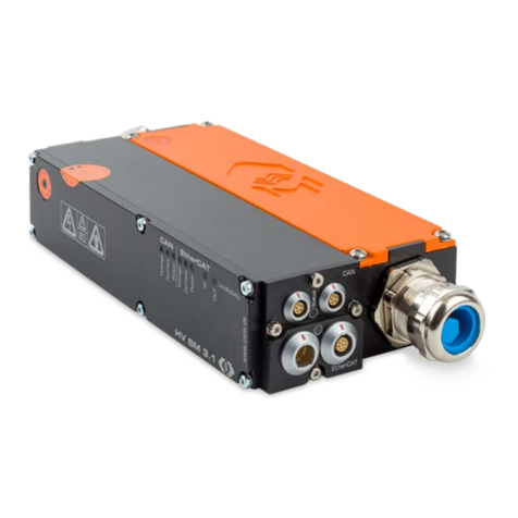
CSM ECAT STGMM 6 User manual

e
ECAT STGMM 6
User Guide
Version 01.10
Innovative Measurement and Data Technology
csm-products.com


ECAT STGMM 6
Copyright
Version 01.10
0
i
User Guide
Copyright
All concepts and procedures introduced in this document are intellectual properties of CSM GmbH
Copying or usage by third parties without written permission of CSM GmbH is strictly prohibited.
This document is subject to change without notice!
Trademarks
All trademarks being mentioned in this document are properties of their respective owners.
Contact Information
CSM offers support for its products during the entire product life cycle. Updates for all components (e.g.
documentation and configuration software) will be provided on the CSM website as soon as they
become available. It is therefore highly recommended to check the download area on the CSM website
at least once per month to stay up-to-date.
Germany (Headquarters)
United States
Address
CSM Computer-Systeme- Messtechnik
GmbH
Raiffeisenstrasse 36
D-70794 Filderstadt, Germany
CSM Products, Inc.
545 Dakota Street
Unit A
Crystal Lake
IL 60012
Phone
+49 (0)711 77964 20
+1 815 444 1671
Fax
+49 (0)711 77964 40
+1 815 444 1674
E-mail
info@csm.de
sales@csmproductsinc.com
Internet
German: http://www.csm.de
English: http://www.csm-products.com
http://www.csmproductsinc.com
Disposal/Recycling of Product
When this crossed-out wheeled bin symbol is attached to a product it means that
the product is covered by the European Directive 2002/96/EC.
Correct disposal of your old product helps to prevent potential negative
consequences for the environment and human health.
Please inform yourself about the local separate collection system for electrical and
electronic products.
Please act according to your local rules and do not dispose of your old products
with your normal household waste.

ECAT STGMM 6
User Guide
ii
Version 01.10
User Guide

ECAT STGMM 6
Table of contents
Version 01.10
0
iii
User Guide
TABLE OF CONTENTS
1INTRODUCTION .................................................................................................. 1
1.1 About this user guide .......................................................................................................... 1
1.2 Symbols and writing conventions...................................................................................... 1
1.3 Warning sign ........................................................................................................................ 2
1.4 Mandatory signs................................................................................................................... 3
1.5 List of abbreviations ............................................................................................................ 3
1.6 Legal disclaimer ................................................................................................................... 4
1.7 Warranty and warranty exclusion ...................................................................................... 4
1.8 ESD Information ................................................................................................................... 4
2SAFETY INSTRUCTIONS.................................................................................... 5
2.1 General safety instructions................................................................................................. 5
2.2 Operator’s obligation........................................................................................................... 5
3PRODUCT DESCRIPTION .................................................................................. 6
3.1 Product overview ................................................................................................................. 6
3.1.1 Connectors and components..................................................................................... 7
3.1.2 Functional description LEDs ...................................................................................... 8
3.1.2.1 Indicator LEDs Link/Activity IN and OUT.................................................... 8
3.1.2.2 Status LED.................................................................................................. 8
3.1.2.3 Channel LEDs............................................................................................. 9
4MOUNTING AND INSTALLATION .................................................................... 10
4.1 Before mounting the device.............................................................................................. 10
4.2 Mounting ECAT STGMM 6................................................................................................. 10
4.3 Installing ECAT STGMM 6 ................................................................................................. 12
4.3.1 Before installing the device...................................................................................... 12
4.3.2 Connectors............................................................................................................... 12
4.3.2.1 IN socket................................................................................................... 12
4.3.2.2 OUT socket............................................................................................... 13
4.3.2.3 Measurement input socket ....................................................................... 14
4.3.3 Strain gauge connection diagrams .......................................................................... 15
4.3.3.1 4- and 6-wire full bridges .......................................................................... 15
4.3.3.2 Strain gauge full bridge in 4-wire connection ........................................... 16
4.3.3.3 Strain gauge full bridge in 6-wire connection ........................................... 17
4.3.3.4 Half bridge ................................................................................................ 18
4.3.3.5 Half bridge with "Free Factor"................................................................... 19
4.3.3.6 Connecting the cables .............................................................................. 20
4.3.3.7 Connecting the power supply ................................................................... 20

ECAT STGMM 6
Table of contents
User Guide
iv
Version 01.10
User Guide
5APPLYING ECAT STGMM 6 ............................................................................. 22
5.1 Example .............................................................................................................................. 22
5.2 Configuring ECAT STGMM 6 ............................................................................................ 23
5.2.1 Dialogs and windows ............................................................................................... 24
5.2.2 Offline configuration................................................................................................. 25
5.2.3 Online configuration................................................................................................. 27
5.2.3.1 Preparing configuration ............................................................................ 27
5.2.3.2 Starting xx-Scan Config and selecting the communication interface ....... 27
5.2.3.3 Setting configuration parameters.............................................................. 28
5.2.3.4 Creating a new configuration file .............................................................. 30
5.2.3.5 “Scan Bus” and “Auto-Configuration” ....................................................... 31
5.2.3.6 Configuring measurement channels......................................................... 34
5.2.3.7 Configuring ECAT STGMM 6 ................................................................... 39
5.2.3.8 Saving configuration in A2L file ................................................................ 41
6MAINTENANCE SERVICES AND CLEANING INSTRUCTIONS ...................... 43
6.1 Maintenance and repair ..................................................................................................... 43
6.2 Cleaning instructions ........................................................................................................ 43
7APPENDIX ......................................................................................................... 44
7.1 Measurements with strain gauges ................................................................................... 44
7.1.1 What is "strain"?....................................................................................................... 44
7.1.2 Strain gauges........................................................................................................... 44
7.1.3 Using bridge circuits for strain gauge measurements ............................................. 44
7.1.4 Using ECAT STGMM 6 for strain gauge measurements ........................................ 47
7.1.4.1 Full bridge ................................................................................................. 48
7.1.4.2 Half bridge ................................................................................................ 49
7.1.4.3 Diagonal bridge......................................................................................... 51
7.1.4.4 Half bridge with transverse STG............................................................... 53
7.1.4.5 Full bridge with transverse STGs ............................................................. 55
7.1.4.6 Half bridge with free factor........................................................................ 59
7.1.4.7 Full bridge with free factor ........................................................................ 65
7.2 List of figures ..................................................................................................................... 67
7.3 List of tables ....................................................................................................................... 68

ECAT STGMM 6
Introduction
Version 01.10
0
1
User Guide
1 Introduction
1.1 About this user guide
This user guide contains important information for handling the product the product. Please read the
entire document carefully before installation and initial operation.
1.2 Symbols and writing conventions
Symbols/writing
conventions
Meaning
Application Example
User instruction
Click on OK to confirm the entry.
Result of an action
The following dialog opens.
→
Cross reference to further
information
See also chapter 1.7 “Warranty and warranty
exclusion”.
This pictogram indicates impor-
tant hints or additional infor-
mation on a specific topic.
Options | Interface
Menu selection
Menu options, options and
buttons are highlighted in bold.
The vertical bar “|” separates
the menu from the menu
command. The example to the
right means: Click on the
Options menu and select the
option Interface.
Select Options | Interface.
(Options | Interface)
A menu option integrated into
the text.
The CAN interface is selected via the Inter-
face dialog (Options | Interface).
(Ctrl + I)
Key shortcut
Key shortcuts are highlighted in
bold and are mentioned in
addition to the menu option, if
applicable.
The example to the right
means: As an alternative to the
menu selection, the option can
also be called up by using the
key sequence Ctrl + I.
Select Options | Interface
(Ctrl + I)
Tab. 1-1: Symbols and writing conventions

ECAT STGMM 6
Introduction
User Guide
2
Version 01.10
User Guide
1.3 Warning sign
Warning signs refer to risks which may arise when using the device The non-observance of safety
instructions contained in warning signs may result in serious injuries or danger to life of persons and/or
material damage.
This documentation contains warning signs the user should observe in order to ensure safe operation
and to prevent damage to persons and/or property.
Design of warning signs
A warning sign consists of the following elements:
Warning symbol
Signal word
Source/type of risk
Possible consequences in case of non-observance
Measures to be taken to avoid the risk
Warning symbols used
Symbol
Meaning
Hot surface
This symbol indicates a risk of burns due to hot surfaces.
Tab. 1-2: Warning signs
Signal words
There are two warning sign categories in this user guide using the following signal words:
Signal word
Meaning
CAUTION
…indicates a potential hazard. If the warning sign is not observed, death or serious
injuries might be the result.
Tab. 1-3: Signal words
Example
CAUTION!
Hot surface
Touching the surface may cause serious burns.
Observe safety instructions.
If more than one degree of risk is present, the warning sign representing the highest degree of risk is
used. A warning sign indicating the risk of an injury to persons may also indicate a risk of property
damages.

ECAT STGMM 6
Introduction
Version 01.10
0
3
User Guide
1.4 Mandatory signs
A mandatory sign contains important information regarding the handling of the product described in the
user guide. The non-observance of a mandatory sign may result in malfunction and/or material damage.
A mandatory sign is characterized by a blue symbol and the signal word NOTICE.
Example
NOTICE!
This symbol refers to important information.
Non-observance of this information may impair the proper functioning or
even lead to the damage of the device.
Read the information carefully.
Symbols used
Symbol
Meaning
This symbol refers to important information. Non-observance of this information may
impair the proper functioning or even lead to the damage of the device.
Wear appropriate safety gloves.
Disconnect device before starting to work!
Tab. 1-4: Mandatory signs
1.5 List of abbreviations
Abbreviation
Meaning
ADMM
AD-Scan MiniModule: CSM measurement module for measuring analog voltages
ASAM
Association for Standardization of Automation and Measuring Systems: registered
association, coordinating the development of technical standards. See ASAM.de.
CAN
Controller Area Network: Serial bus system, developed by Bosch for networking
ECUs in vehicles.
CoE
CANopen over EtherCAT Protocol for using the CANopen profile family via
EtherCAT.
DAQ
Data AcQuisition
EtherCAT
EtherCAT is an Ethernet-based field bus system, developed by Beckhoff and the
EtherCAT Technology Group. See Ethercat.de
EMC
Electromagnetic Compatibility
ESD
ElectroStatic Discharge
MC tool
Measurement & Calibration tool
STG
STrain Gauge
STGMM
Strain Gauge MiniModule: CSM measurement module for strain gauge measurements

ECAT STGMM 6
Introduction
User Guide
4
Version 01.10
User Guide
Abbreviation
Meaning
TEDS
Transducer Electronic Data Sheet
VIN
Measured voltage strain gauge
VOUT
Strain gauge bridge excitation voltage
XCP
eXtended Calibration Protocol. See ASAM.de.
Tab. 1-5: List of abbreviations
1.6 Legal disclaimer
This user guide and further technical documents are part of the product and contain important
information for its safe and efficient use. The product is subject to continuous further development in
order to maintain the high level of quality, which implies that technical details may change at short
notice. Thus, it may happen that the information in this document does not correspond with the
technical state of the product. For this reason the manufacturer cannot be held liable for claims
arising from any erroneous content in the product documentation.
CSM GmbH is not liable for technical or editorial errors or any lack of information.
CSM GmbH does not assume any liability for damages resulting from the non-intended use of the
product and/or from the non-observance of its technical documentation, in particular the non-
observance of the safety instructions.
1.7 Warranty and warranty exclusion
The warranty extends to the safety and functionality of the product within the given warranty period. The
manufacturer is not liable for any claims which are based on consequential damage or loss as a result
of the non-function or malfunction of the product.
The warranty is void if
the product is inappropriately used
the product is modified in any way
the information that is part of the product, in particular the safety instructions, is not observed
the product is operated with additional equipment or parts which have not been explicitly endorsed
by the manufacturer of the product.
See also chapter 2.2 “Operator’s obligation”.
1.8 ESD Information
The manufacturer of the product declares that the device ECAT STGMM 6 is in conformity with the
requirements of the European EMC Directive 2004/108/EG.
NOTICE!
Particular care has to be taken concerning ESD.
Do not apply ESD on the inner contacts of the measurement inputs.

ECAT STGMM 6
Safety Instructions
Version 01.10
0
5
User Guide
2 Safety Instructions
This chapter contains important safety information. Please read the following paragraphs carefully.
2.1 General safety instructions
The measurement module ECAT STGMM 6 has been designed and manufactured to comply with the
relevant safety standards. The product is manufactured in due consideration of the standards of an ISO
9001 Quality Management System.
CAUTION!
The surface of the device housing may become very hot when
operated in specific environments (e.g. engine compartment).
Touching the surface may cause serious burns.
Cool down the device before handling.
Wear appropriate protective gloves, if required.
NOTICE!
Proper functioning and electrical safety can only be ensured if the device is
correctly installed.
Make sure that the device is properly installed.
Operate the device only within the specified operation environment.
See datasheet “ECAT STGMM 6” for further information.
2.2 Operator’s obligation
The operator has to make sure that the product is only handled by qualified and authorized personnel.
This applies to all aspects of the device handling.
In addition to the technical documentation of the product, the operator may have to provide further
operating instructions in compliance with the Act on Occupational Safety and Health.

ECAT STGMM 6
Product description
User Guide
6
Version 01.10
User Guide
3 Product Description
The following paragraphs contain general information on the product. Specific technical information can
be found in the datasheet.
See datasheet “ECAT STGMM 6” for further information.
3.1 Product overview
ECAT STGMM 6 is an EtherCAT-based, robust and extremely compact measurement module for strain
gauge measurements. ECAT STGMM 6 features six strain gauge inputs and offers the advantage of
being mechanically compatible to measurement modules of the CSM MiniModule series. Up to 25
measurement modules of the ECAT MiniModule series can be operated via one XCP-Gateway.
ECAT STGMM 6 is operated in an EtherCAT network as EtherCAT slave device. Configuration is carried
out via XCP-Gateway using the configuration software xx-Scan Config. The module is operated using
XCP-capable software (DAQ). ECAT STGMM measurement modules can be directly connected to a
computer if data acquisition software supporting EtherCAT master operation is used.
ECAT STGMM 6 measures the bridge excitation voltage VOUT and the differential bridge voltage VIN
using high-precision ADCs. Both values are filtered and from the filtered values, the voltage ratio
VIN/VOUT , i.e. the bridge unbalance is calculated. The measurement results can also be provided as
strain values in µm/m. Measurement results can be provided in further measurement units, if required.
Key features
Time-synchronous strain gauge inputs with measurement data rates up to 10 kHz per channel
Support of full and half bridge strain gauges with 4- and 6-wire connection
Simple configuration via xx-Scan Config using a universal measurement range
Extremely low power consumption
Very good measurement accuracy under difficult temperature ranges and environmental conditions
High resistance to interference due to ratiometric measuring principle and configurable software filter
Operating temperature: -40 °C to +85 °C
Robust aluminium housing, compatible with MiniModule series devices
Extremely compact EtherCAT measurement module, protection class IP67
Housing types
ECAT STGMM 6 is available in two housing versions: "Standard" (CL) and "Slide Case" (SCL).
See datasheet “ECAT STGMM 6” for further information.

ECAT STGMM 6
Product description
Version 01.10
0
7
User Guide
3.1.1 Connectors and components
The following figures show the standard housing version of an ECAT STGMM 6 measurement module
with its connectors 1).
Fig. 3-1: ECAT STGMM 6, front view (Slide Case SCL)
1. IN socket (chapter 4.3.2.1 "IN socket")
2. Indicator LED referring to 1. (chapter 3.1.2.1 "Indicator LEDs Link/Activity IN and OUT")
3. Status LED (chapter 3.1.2.2 "Status LED")
4. OUT socket (chapter 4.3.2.2 "OUT socket")
5. Indicator LED to 5. OUT (chapter 3.1.2.1 "Indicator LEDs Link/Activity IN and OUT")
6. Channel LEDs 1 - 6 (chapter 3.1.2.3 "Channel LEDs")
7. Measurement inputs 1 - 6 (chapter 4.3.2.3 "Measurement input socket")
Fig. 3-2: ECAT STGMM 6, rear side (Slide Case SCL)
1. Threaded mounting hole for four M4 screws M4 x 8 mm 2)
2. Cable tie eyelets (for cable ties with a width of max. 4 mm)
3. Type label
4. Calibration sticker
5. Sticker: "Do not poke –Do not cover"
6. Ventilation inlet GORE™ membrane
7. Venting groove
See chapter 4.1 "Before mounting the device“ for further information.
1) The measurement inputs of the device in Fig. 1 are equipped with sockets of the type LEMO 1B 8-pole. There may be customer-
specific solutions regarding the sockets. All further technical specification of the measurement module, however, remain
unaffected.
2) The specification “M4 x 8 mm” only applies if a standard mounting angle from the product range of CSM MiniModule accessories
is used. In this case, the screw length may not exceed 8 mm. In case of combination with any other mounting material, a
different screw length may be required.
7
2
6
5
3
1
4
3
2
7
4
6
2
1
5
1
1
1

ECAT STGMM 6
Product description
User Guide
8
Version 01.10
User Guide
3.1.2 Functional description LEDs
3.1.2.1 Indicator LEDs Link/Activity IN and OUT
The indicator LEDs for the sockets IN and OUT (see Fig. 3-1) are lit or are flashing if the ECAT STGMM 6
is electrically connected to an XCP-Gateway or another ECAT measurement module and or if data is
being transferred. Possible status categories are:
LED
Meaning
Color
Status
Green
permanently lit
Ethernet connection to ECAT STGMM 6 has been established,
no data transfer.
Green
flashing
Ethernet connection is active, i.e. data is being transferred
Red
permanently lit
Measurement module is switched on or connection to power
supply has been established, but there is no Ethernet
communication.
-
off
No measurement module or XCP-Gateway connected
Tab. 3-1: Indicator LEDs IN / OUT
3.1.2.2 Status LED
After the measurement module has been switched on, the two-colored status LED (see Fig. 3-1) is lit in
green for approx. 1.2 seconds and fades out. Possible status categories are:
LED
Meaning 3)
Color
Status
Green
flashing
Device is in status PRE-OPERATIONAL.
Green
flashing
Device is in status SAFE-OPERATIONAL.
Green
permanently lit
Device is in status OPERATIONAL.
Red
flashing
Configuration error
Red
permanently lit
no communication with EtherCAT slave controller
Tab. 3-2: Status LED
3) Status designations according to Beckhoff and EtherCAT Technology Group EtherCAT standard

ECAT STGMM 6
Product description
Version 01.10
0
9
User Guide
3.1.2.3 Channel LEDs
The channel LEDs provide information on the status of the corresponding channel.
LED
Meaning
Error code in measurement
software
off
No bridge excitation voltage.
"HARDWARE_ERROR”
100 % green
Channel is functioning fault-free.
50 % green,
50 % off
Channel selected via xx-Scan Config
80 % green,
20 % red
Bridge excitation voltage out of order.
This might be caused by a short circuit in the
sensor cable or if a non-appropriate strain
gauge is in use (< 120 Ω).
"SUPPLY_RANGE_OVERFLOW”
or
"SUPPLY_RANGE_UNDERFLOW”
20 % green,
80 % red
Measured values are out of the measurement
range ±200 mV. This may be the case if the
bridge is extremely unbalanced (e.g. measure-
ments with quarter bridges and long supply
lines).
"INPUT_RANGE_OVERFLOW”
or
"INPUT_RANGE_UNDERFLOW”
100 % red
ADC defective.
Send the measurement module in for repair.
20 % red,
80 % off
The measured value is out of the range which
has been set in the Measurement Range field
of the channel configuration dialog.
See chapter 5.2.3.6 "Configuring measurement
channels“ for details.
"OUTPUT_RANGE_OVERFLOW”
or
"OUTPUT_RANGE_UNDERFLOW”
Tab. 3-3: Channel LEDs

ECAT STGMM 6
Mounting and installation
User Guide
10
Version 01.10
User Guide
4 Mounting and Installation
The following paragraphs comprise important information on mounting and installing the device.
Measurement modules of the MiniModule series are robust devices, designed for being mounted in
vehicles for permanent operation. To ensure fault-free operation and a long product life, however, certain
basic requirements need to be taken into account.
4.1 Before mounting the device
ECAT STGMM 6 measurement modules are equipped with a GORE™ membrane and a venting groove.
They are essential to ensure the fault-free regulation of pressure and humidity. To ensure reliability and
performance of the device, it is absolutely essential that the small ventilation inlet it the rear side of the
housing (see Fig. 3-2) is not blocked or restricted in any way. If the ventilation inlet is blocked, conden-
sation may dam up inside the housing and cause damage to the device.
NOTICE!
The GORE membrane is needed to regulate pressure and humidity.
Do not block the ventilation inlet for the GORE™ membrane when
mounting the device.
NOTICE!
Proper functioning and electrical safety can only be ensured if the device is
correctly installed.
Make sure that the device is properly installed.
Operate the device only within the specified operation environment.
See datasheet “ECAT STGMM 6” for further information.
4.2 Mounting ECAT STGMM 6
NOTICE!
Strong magnetic fields induced e.g. by permanent magnets may impair the
proper functioning of the measurement module.
Never attach the device to a permanent magnet.
CSM offers a mounting kit for devices in standard housing.
Please contact the sales department for further details.

ECAT STGMM 6
Mounting and installation
Version 01.10
0
11
User Guide
Preconditions
The venting groove and the ventilation inlet of the GORE™ membrane (see Fig. 3-2) are not blocked
or obstructed in any way.
The mounting location provides a firm base. Mounting the device on a soft base (e.g. sponge rubber)
may block the venting groove and cause damage to the device.
When choosing the mounting place, make sure that the ventilation hole will not be permanently
immersed in water or any other liquid.
The mounting site allows for sufficient space to connect and disconnect the cables without clamping
or pinching them.
Parts/material required
4 M4 screws 4) and a matching screwdriver
if required, further mounting material (e.g. mounting bracket)
or
4 appropriate cable ties
Mounting the device
Fix the measurement module at the mounting position using the four screws.
or
Fix the measurement module at the mounting position using the cable ties.
NOTICE!
Drilling additional holes into the housing may impair the proper functioning
of the device or even destroy it.
Do not drill any additional holes into the housing.
Mounting slide case measurement modules
If multiple measurement modules are used, slide case housings offer the advantage that not every
device needs to be mounted separately. This is of particular benefit when multiple measurement
modules are to be mounted. Further modules are simply stacked on the already mounted one. Suitable
adapter plates are available to attach different-sized slide case housings to each other. The first and the
last module of a module stack are fixed with mounting angles.
See datasheet "CSM MiniModule Accessories" for details.
4) If a standard mounting angle is from the product range of CSM MiniModule accessories is used, the screw length may not
exceed 8 mm (M4 x 8mm). In case of combination with any other mounting material, a different screw length may be required.

ECAT STGMM 6
Mounting and installation
User Guide
12
Version 01.10
User Guide
4.3 Installing ECAT STGMM 6
4.3.1 Before installing the device
CSM offers a wide range of cables for connecting ECAT measurement
modules.
See datasheet “CSM MiniModule Accessories” for details.
Please contact the sales department for further details.
CSM offers a calibration and repair service for ECAT STGMM 6
measurement modules.
See chapter 6.1 "Maintenance and repair".
4.3.2 Connectors
The measurement module is connected to the XCP-Gateway (alternatively to an EtherCAT master) or to
an upstream EtherCAT measurement module via the IN socket. The OUT socket is designed for daisy-
chaining the device with further EtherCAT measurement modules. EtherCAT measurement modules
receive their power supply from the XCP-Gateway, i.e. via the same cable connection
(see chapter 4.3.2.1 and 4.3.2.2). The sensors (strain gauges) are connected to the measurement inputs
1 - 6 (see chapter 4.3.2.3).
4.3.2.1 IN socket
By default, a LEMO 1B connector is used for the IN socket. To have the device equipped with a different
socket, please contact CSM.
For connecting a cable to this socket the following plug is needed: FGL.1B.308.CLLxxxxx 5).
IN socket
Pin
Signal
Description
1
VBatt +
Power supply, plus
2
GND
Ground
3
RX -
Ethernet: Receive data, minus
4
TX -
Ethernet: Transmit data, minus
5
RX +
Ethernet: Receive data, plus
6
GND
Ground
7
VBatt +
Power supply, plus
8
TX +
Ethernet: Transmit data, plus
Tab. 4-1: IN socket: Pinning
5) "xxxxx" is a placeholder. The actual designation depends on the diameter of the used cable.

ECAT STGMM 6
Mounting and installation
Version 01.10
0
13
User Guide
NOTICE!
The power supply is wired through from the IN socket to the OUT socket.
Thus, a signal at a specific pin of the IN socket is always available at the
OUT socket, too.
Make sure that this work is only carried out by qualified and trained
personnel.
4.3.2.2 OUT socket
By default, a LEMO 1B connector is used for the OUT socket. To have the device equipped with different
sockets, please contact CSM.
For connecting a cable to this socket the following plug is needed: FGA.1B.308.CLAxxxxx 6).
OUT socket
Pin
Signal
Description
1
VBatt +
Power supply, plus
2
VBatt +
Power supply, plus
3
GND
Ground
4
RX +
Ethernet: Receive data, plus
5
TX -
Ethernet: Transmit data, minus
6
RX -
Ethernet: Receive data, minus
7
GND
Ground
8
TX +
Ethernet: Transmit data, plus
Tab. 4-2: OUT socket: Pinning
6) "xxxxx" is a placeholder. The actual designation depends on the diameter of the used cable.

ECAT STGMM 6
Mounting and installation
User Guide
14
Version 01.10
User Guide
4.3.2.3 Measurement input socket
By default LEMO 1B sockets are used for the measurement inputs. To have the device equipped with
different sockets, please contact CSM. For connecting a cable to this socket, a plug of the type
FGG.1B.308.CLADxxxxx 7) is needed. Matching plugs and termination plugs are available from CSM.
ART1030403 LEMO 1B Plug 8-pin (Code G)
ART1030600 MiniModul K68 Protection Plug (L1B)
Measurement input
socket
Pin
Signal
Description
1
VIN -
Measured voltage (-)
2
VIN +
Measured voltage (+)
3
VOUT -
Bridge excitation voltage, ground
4
VOUT +
Bridge excitation voltage, plus
5
VSENSE -
Sense minus
6
VSENSE +
Sense plus
7
Channel shield
Shield for measurement signal
8
Data
Data line (TEDS)
Housing
Cable shield
Outer shield (housing)
Tab. 4-3: Socket measurement input: Pinning
7) "xxxxx" is a placeholder. The actual designation depends on the diameter of the used cable.
Table of contents
Other CSM Control Unit manuals
Popular Control Unit manuals by other brands

UniData Communication Systems
UniData Communication Systems Neon 2000 Family manual
Texas Instruments
Texas Instruments ADS8555EVM-PDK user guide
barfield
barfield DC400 User instruction
Zamel
Zamel Exta LDM-11 Manual instruction

Ring Engineering
Ring Engineering RailPro LM-3S-G user manual
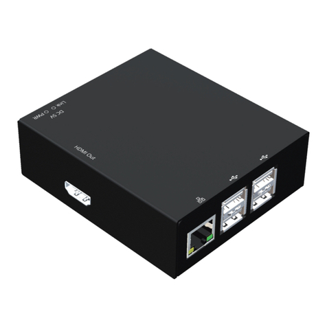
gofanco
gofanco Prophecy PRO-HDExtIP-CTRL user guide
