Pipe connections
General
Pipes and other cold surfaces must be insulated with dif-
fusion-proof material to prevent condensation. Where
the cooling demand is high, fan convectors with drip trays
and drain connection are needed.
The brine circuit must be supplied with a pressure expan-
sion vessel. If there is already a level vessel installed this
should be replaced.
Check valve, mixing valve and circulation
pump
႑Install the supplied check valve between two T-pipe
connections to PCS 44 nearest the heat pump on
brine in (see the outline diagram).
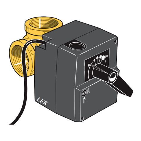
႑Install the mixing valve (QN18) on the flow line to the
fan convector (port 1) so that port 1 is open towards
port 2 (blue coloured) when the motor is in idle mode.
In the event of a signal, port 1 opens towards port 3
(red coloured). The return line from the fan convector
is connected to the mixing valve (port 2) as well as
brine in closest to the heat pump.
႑Install the extra circulation pump (GP13) after the
mixing valve (QN18) on the flow line to the fan con-
vector.
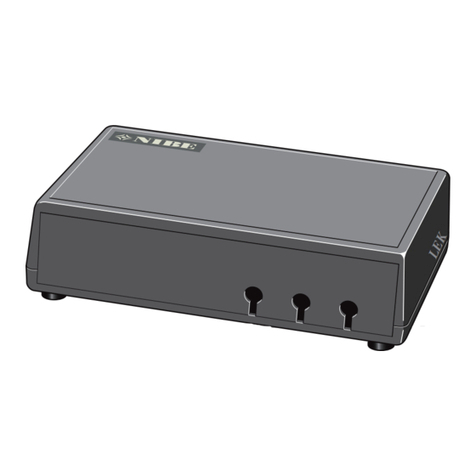
LEK
Colour marking
1
2
3
Temperature sensor
႑Install the flow temperature sensor for the cooling
system (BT64) on the pipe after the circulation pump
(GP13) in the direction of flow.
႑Install the return line sensor for the cooling system
(BT65) on the pipe from the cooling system.
Install the temperature sensors with cable ties with the
heat conducting paste and aluminium tape. Then insulate
with supplied insulation tape.
NOTE
Sensor and communication cables must not be
placed near power cables.
Pump and pressure drop diagrams
Flöde
kPa
l/h
10
200
0
0
20
400
30
600
40
800
50
1000
60
1200
70
1400 1600 1800 2000
l/s
0,50,40,30,20,10
Max flöde:1700 l/h
Available pressure Max flow: 1700 l/h
Flow
10
B


