Relcom CBR-7AC User manual

CBR-7 Installation and Testing 501-281, Rev C.0
1
Installation
and Testing
5 Mbit/s
Repeater
Carrier-band
to Single-mode
Fiber Optic
Models
CBR-7AC
CBR-7DC
This manual describes the procedures for installing and testing the CBR-7 Fiber-Optic Repeaters.
oFor an explanation of how to install the coaxial cable part of the carrierband network, see
Relcom’s Carrier-band Network Handbook.
oFor an explanation of how fiber optics works, see Relcom’s Guide to Industrial Fiber Optics.
oFor an explanation about how repeaters work, and CBR-7 system design information, see
Relcom’s CBR-7 System Design Application Note, document 501-276.
oFor technical specifications, see the CBR-7 product specification, document PS-029.

CBR-7 Installation and Testing 501-281, Rev C.0
2
Repeater Installation
The Repeater is connected to segments of the Carrier-band network like any other station
through a drop cable and a tap. The following should be considered when installing a Repeater:
oPlace the Repeater where its indicator lights can be seen. This will help identify and isolate
network problems if they occur.
oWhile the Repeater is fully enclosed, it is not waterproof. Install the Repeater in a dry place.
oThe Repeater operates at temperatures between -20 and +65 °C (-4 to 150 °F). However, do
not install the Repeater in places where it will be heated by other equipment or where there is
no airflow.
oA rack mounting kit for the Repeater is available.
Power
The Repeater is powered from an AC or DC power source depending on the option chosen.
CBR-7AC power input range is from 85 to 240 volts, 47 to 63 Hertz. The power cord connection
to the Repeater is a standard IEC 320 plug. Different types of power cords can be used to adapt
to various types of power sources.
CBR-7DC power input range is from 18 to 36 Volts DC.
CBR-7DC:
WARNING: FOR PERMANENTLY CONNECTED EQUIPMENT, A READILY
ACCESSIBLE DISCONNECT DEVICE SHALL BE INCORPORATED IN THE FIXED
WIRING.
AVERTISSEMENT: POUR LES ÉQUIPEMENTS RACCORDÉS EN PERMANENCE, UN
DISPOSITIF DE DÉCONNEXION FACILEMENT ACCESSIBLE DOIT ÊTRE INCORPORÉ
DANS LE CÂBLAGE FIXE.
Grounding
Both F-connectors are grounded to the Repeater's case for reducing RFI emissions.
The Repeater's case is connected to the front panel TEST F-connector, to the mains ground
connection on the AC model, to the GND terminal on the DC model, and to the ¼-20 stud on the
back panel.
Attach a ground wire from the ground stud to the grounding facilities provided in the building.
Use a grounding wire that has a current carrying capacity equal or greater than that of the drop
cable outer conductor.

CBR-7 Installation and Testing 501-281, Rev C.0
3
Hazardous Area Warning
For both AC and DC Repeaters, users are warned not to disconnect power to the Repeater
while the circuit is alive unless the location is known to be non-hazardous.
AC Power plugs

CBR-7 Installation and Testing 501-281, Rev C.0
4
Testing
A self-testing capability is provided for checking the operation of the Repeater before it is
connected to a network or if a malfunction is suspected.
1. Connect the Repeater to a power source.
The power indicator light, PWR, should be ON. The other indicator lights should be OFF
2. Connect the short test cable from the TEST F-connector to the F-connector labeled A.
3. If another Fiber Optic Repeater is available, connect the XMIT line of the first Repeater to the
REC line on the second Repeater. The ACTIVE light for the Fiber Optic input on the second
Repeater should be ON.
4. Connect F-connector A of the second Repeater with a 75 ohm terminated cable to an
oscilloscope. The second Repeater will put out signal bursts on its connector A. The peak-to-
peak voltage of the bursts should be between 3.0 and 3.9 Volts. (Keep in mind that the cable
gives a direct reading and is not a 10:1 probe.)
Repeat the procedure with the Repeaters reversed. Test only one direction at a time with a single
fiber optic cable connecting the two repeaters.
There is no built-in provision for testing the Fiber Optic input or output other than to connect two
Repeaters back-to-back and use the TEST signal to check the operation of the Fiber Optic ports
as described above.
If these tests do not produce the specified results, the Repeater(s) may be defective and should be
returned for repair.
THERE ARE NO USER ADJUSTMENTS OR REPAIRS TO BE MADE INSIDE THE
REPEATER.
For guidance about installing the carrier-band segment of the network, see Relcom's Carrier-
band Network Handbook.

CBR-7 Installation and Testing 501-281, Rev C.0
5
Troubleshooting
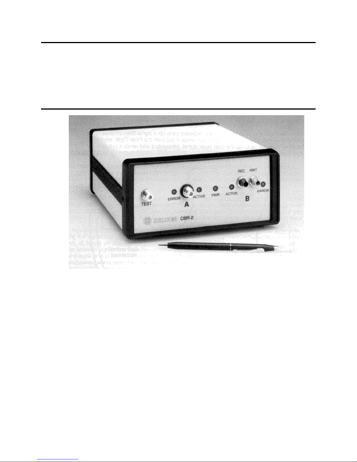
During normal Repeater operation, the PWR light is ON, the two ACTIVE lights are ON and
OFF intermittently and the ERROR lights may blink occasionally. If not, check the following list
of symptoms and possible corrections:
1. The PWR light is OFF
Check the power cord and the power source.
2. An ACTIVE light is ON indicates that data is being received from that network segment.
Normally the ACTIVE light shows differing levels of brightness indicating the relative amount
of data received from the corresponding segment. If the light is solidly OFF, no data is being
received. The causes may be:
The Repeater is disconnected from the network segment. Check the network wiring.
None of the stations on the network segment are transmitting.
The signal from the coaxial cable to the Repeater is too low. Check the signal level with the
Carrier-band Tester.
The Repeater is defective. Check the Repeater with the test procedures above.
3. If the ERROR indicator light blinks ON the Repeater has received a frame with an error. The
ERROR light should blink ON no more than once every 20 seconds. This corresponds to a bit
error rate of about 10 -8 or one bad bit received for one hundred million sent. If the ERROR light
blinks ON more frequently:
There may be excessive noise on the network coaxial cable segment. Use the Carrier-band Tester
to determine the noise level.
The Repeater may be receiving a signal from the coaxial cable that is too low. This may be a
result of improper network design, failure in the cables or taps, or some station not transmitting
at a sufficiently high signal level.
Note: Some systems are setup to switch between cables on a regular basis. These transitions may
also cause the ERROR indicator to blink; these ERROR indications are part of the normal
operation of the system and they can be ignored.
The Repeater detects two types of errors:
a. If the Repeater detects a start delimiter of a frame but no end delimiter before the received
signal drops below threshold.
b. If the Repeater detects three consecutive "highs" or three consecutive "lows" within a bit cell.
These are violations of the data encoding used in carrier-band.
The Repeater does not check frame CRCs or other types of network errors. The ERROR
indicator lights are only a diagnostic aid for pointing to a segment that may be generating more
than the expected number of errors.
THERE ARE NO USER ADJUSTMENTS OR REPAIRS THAT CAN BE PERFORMED ON
THE REPEATER. IF THE REPEATER DOES NOT WORK PROPERLY, RETURN IT TO
RELCOM FOR REPAIR OR REPLACEMENT.

CBR-7 Installation and Testing 501-281, Rev C.0
6
Fiber-Optic Testing
When the CBR-7 repeaters and the optical components are installed, they must be tested to verify
that they work properly.
The fiber optic components between two CBR-7 repeaters must be able to carry light signals
from the transmitter of one repeater to the receiver of the other. The components include the
main cable between the two repeaters, and may also include a patch panel at each end, the patch
cables, and an attenuator. Some installations may also have more optical interconnection
components.
Patch Panel
Patch Panel
The total attenuation (insertion loss) of optical components must be at least 15
dB but not more than 24 dB. If necessary, an attenuator must be used on the
transmit side of the main fiber-optic cable.
For example: Assume that each optical connection has an attenuation of 0.5 dB and there are
two connections at the transmitter side and two at the receiver side. The main cable is 8 km long
and has an attenuation of 0.4 dB/km for a total attenuation of 3.2 dB. The total fiber-optic
attenuation is
2 X 0.5 + 3.2 + 2 X 0.5 = 5.2 dB
To get into the needed attenuation range, a 10 dB attenuator needs to be put at the transmitter
output. The calculated attenuation of all the fiber optic components is:
10 + 5.2 = 15.2 dB.

CBR-7 Installation and Testing 501-281, Rev C.0
7
Attenuation Measurement
Determine the light output level of the CBR-7 transmitter. Disconnect all patch cables from the
transmitter. Connect a coaxial cable between the Test and the A connectors of the CBR-7.
Connect a light meter to the transmit connector. Power the CBR-7 and measure the transmitter
light level.
CBR-7
A
B
XMIT
Rec
TEST -5 dBm
Light
Meter
Disconnect the light meter from the transmitter. Connect the patch cable to the transmitter and
all the other optical components. Measure the light level at the receiver of the corresponding
CBR-7 repeater. This should be close to the level measured at the transmitter minus the
calculated attenuation determined at design.
Patch
Cable Patch
Cable
Cable
Patch Panel
Patch Panel
Attn
CBR-7 A
B
XMIT
REC
TEST
-11.2dBm
Light
Meter

CBR-7 Installation and Testing 501-281, Rev C.0
8
From the example above, if the light measured at the receiver is -11.2dBm then the Measured
Attenuation of the optical components is:
-5dBm (the measured transmitter output) – (-11.2dBm) = 6.2 dB
This is 1 dB more than the calculated attenuation value. A variation of 1 dB is not critical. A
larger deviation would indicate a problem with the attenuation estimate and might indicate that
optical components are out of specification.

CBR-7 Installation and Testing 501-281, Rev C.0
9
Return Loss
CBR-7 performance depends on low return losses (reflections) of the optical components. This
must be measured to be sure all the optical components are within their specifications.
Transmit side
With all the optical components connected together, disconnect the patch cable at the CBR-7
transmitter and measure the return loss of the optical components without the attenuator with an
Optical Time Domain Reflectometer, OTDR, as shown below. Neglect any near-end readings.
The return loss of interest is that at the end of the cable as seen from the transmitter end. Note
the value as Transmit Return Loss.

CBR-7 Installation and Testing 501-281, Rev C.0
10
Receiver side
With all the optical components connected, disconnect the CBR-7 at the receiver. (Be sure that
the CBR-7 on the transmit side is not powered). Measure the return loss of the optical
components as shown below. Neglect any near-end readings. The return loss of interest is that
at the end of the cable as seen from the receiver end. Note this as Receive Return Loss.
For proper operation of the CBR-7 repeaters over the fiber optic cable
The value of the attenuator + Transmitter Return Loss + Receiver Return
Loss must be at least 48 dB.
If this is not the case, there is something wrong with the attenuator or the patch cable assemblies
that produces extraordinary reflections.
In the example above, the attenuator’s value is 10 dB. Assume the measured Transmitter Return
Loss is 20.2 dB and the Receiver Return Loss is measured to be 32.2 dB. Then
10 Attenuator value
20.2 Transmit Return Loss
32.2 Receive Return Loss
62.4 Total
In this example, the total of 62.4 is over the required 48.
For both the Transmitter and Receiver return loss measurements, neglect any near-end readings.
The measurement of interest is at the end of the cable. If there are other reflections that are not at
the cable’s length mark and these are closer to the measurement of interest than 10 dB, then there
is something wrong with the optical components at that location.

CBR-7 Installation and Testing 501-281, Rev C.0
11
Here is an example:
The top of the screen is at -10 dB. There are two reflections. One is at 4 km and the other at 8
km, at the end of the cable. The one at 4 km is 15 dB below the one at the end and it can be
neglected since it is more than 10 dB below the reflection of interest at the end of the cable. The
reflection at the end of the cable is at -14 dB. The return loss at the end of the cable due to this
reflection is 14 dB, as seen from the other end of the cable where the measurement is made.
This manual suits for next models
1
Other Relcom Repeater manuals
Popular Repeater manuals by other brands

Gefen
Gefen DVI-141HD manual

Channel Vision
Channel Vision IR Reciever IR-2005 user guide

Siemens
Siemens Gigaset SE365 WLAN operating instructions

IMC Networks
IMC Networks iMcV-DS3/E3/STS Operation manual

Visonic
Visonic MCX 610 - INSTALLER GUIDE installation instructions

Siemens
Siemens Gigaset 108 user guide