Dekolink MW-BDA-ESMR-25W90 806-15 User manual

©2004 Dekolink Wireless Ltd.—All Rights Reserved
iDEN Outdoor
Repeater
Hardware Manual -MW-BDA-ESMR-25W90
Release 1.01_5/5/04

Confidential
Authorized Customer Use
This document may be used in its complete form only and is solely for the use of
Dekolink Wireless Ltd. employees and authorized Dekolink Wireless Ltd. channels or
customers.
The material herein is proprietary to Dekolink Wireless Ltd. Any unauthorized
reproduction; use or disclosure of any part thereof is strictly prohibited.
Dekolink Wireless Ltd. reserves the right to make changes in specifications at any time
without notice. The information furnished by Dekolink Wireless Ltd. in this document
is believed to be accurate and reliable. However, Dekolink Wireless Ltd. assumes no
responsibility for its use.
All trademarks and registered trademarks are the property of their respective owners.
Dekolink Wireless Ltd. – Elisra Group
postal 16 Bazel St., Kiryat-Arieh, Petah-Tikvah 49001 Israel
Tel +972 3 918-0180
fax +972 3 918-0190
e-mail marketing@dekolink.com
website www.dekolink.com
Document Number:
300MB50030

INTRODUCTION
Dekolink™—IDEN Repeater Hardware Manual 1
Table of Contents
1. Introduction............................................................................................3
1.1. Intended Audience .................................................................................................. 3
1.2. Glossary ...................................................................................................................4
2. Content List............................................................................................ 5
3. Block Diagram ........................................................................................6
4. Repeater Overview .................................................................................7
4.1.Components List ...................................................................................................... 8
4.1.1.Components Description ............................................................................ 8
4.1.2. Channeler.................................................................................................. 8
4.1.3. Repeater Monitor Module.......................................................................... 8
4.1.4. Control Box................................................................................................ 9
4.1.5. Power Supply ............................................................................................ 9
4.1.6. Duplexers .................................................................................................. 9
4.1.7. Power Amplifiers ....................................................................................... 9
5. Repeater Features ................................................................................10
5.1. Monitor And Control.............................................................................................. 10
5.2. SALC (Smart ALC) Function................................................................................. 10
5.3. Automatic Level Control (ALC) Function........................................................... 11
5.4. RF Gain Setting...................................................................................................... 12
6. System Installation............................................................................... 13
6.1. Safety Instructions ................................................................................................ 13
6.2. Software Installation ............................................................................................. 14
6.3. Hardware Equipment Instructions....................................................................... 14
6.3.1. Repeater Installation ............................................................................... 15
6.3.2. Base/Donor Antenna Installation............................................................. 15
6.3.3. Mobile/Service Antenna Installation ........................................................ 15
6.3.4. AC Power Connection ............................................................................. 16
6.3.5. PC/Laptop Connection ............................................................................ 16
6.4. System Initialization - Setting The Repeater Parameters.................................. 17
6.4.1. Configuration Tab................................................................................... 19
6.4.2. Parameters and Control Tab................................................................... 20
6.4.3. Repeater Alarms ..................................................................................... 22
6.5. System Activation ................................................................................................. 23

2Release 1.00
Authorized Customer Use
A. Appendix: Alarms ............................................................................... 24
Power Amplifier..................................................................................................24
Channeler ..........................................................................................................24
Channeler Lock-Detect ......................................................................................24
Voltage Standing Wave Ratio (VSWR)..............................................................25
Measurements ...................................................................................................25
B. Appendix: Hardware Description ....................................................... 26
Repeater Mechanical Outline ............................................................................26
C. Appendix: Repeater Specifications.................................................... 27
Electrical Specifications .....................................................................................27
Mechanical Specifications .................................................................................28
Environmental Specifications.............................................................................28
D. Appendix: Installation of the Repeater in a Laboratory Setting..... 29
E. Appendix: Maintenance And Troubleshooting ................................. 30
Periodic Maintenance ........................................................................................30
Troubleshooting table ........................................................................................30
F. Appendix: RF Exposure Warning ....................................................... 32
G. Appendix: Dekolink Wireless Limited Warranty ............................... 33

INTRODUCTION
Dekolink™—IDEN Repeater Hardware Manual 3
1. INTRODUCTION
The Repeater assembly provides exceptional repeater performances to extend the
coverage area of radio communications in buildings and RF shielded environments.
Features such as high linearity power amplifiers are contributing for the overall
improved system linearity performances. The unit is based on a duplexed path
configuration, having sharp out of band attenuation filters to improve the isolation
between the receiving and transmitting paths. In addition the unit consist of SAW filter
in each path for better spectrum purity.
The following are some of the features of the Dekolink Repeaters:
• 4W composite output power
• 90 dB RF gain
• Flexible software controlled Band Pass Filter center frequency
• Relatively small dimensions
• Local and remote (optional) monitor and control (software enabled)
• High spectral purity
1.1.Intended Audience
This document is intended for Dekolink customers. It is assumed that the customers
installing, operating, and maintaining the Dekolink Repeaters are familiar with the
basic functionality of repeaters.

4Release 1.00
Authorized Customer Use
1.2.Glossary
The following is a list of abbreviations and terms used throughout this document.
Abbreviation/Term Definition
Downlink
The path covered from the Base
Transceiver Station (BTS) to the
subscribers/service area via the
repeater
iDEN Iintegrated Digital Enhanced Network
IF Intermediate Frequency
IP3 Third order Intercept Point
RMT Repeater Management Tool Software
PLL Phased Locked Loop
RF Radio Frequency
Uplink
The path covered from the
subscribers/service area to the Base
Transceiver Station (BTS) via the
repeater
SALC Smart ALC (Automatic Level Control)
VSWR Voltage Standing Wave Ratio

CONTENT LIST
Dekolink™—IDEN Repeater Hardware Manual 5
2. CONTENT LIST
Dear Valued Customer,
Thank you for selecting Dekolink Wireless. To help us assure that we have completed
the order to your satisfaction, please check the contents of this package(s) against the
list below before discarding any packaging. Items in your order may be shipped in
multiple packages. If an item is missing or has been damaged, contact your Dekolink
Sales and Service Office immediately.
Product Number Description Quantity OK
300MB50000 MW-BDA-ESMR-25W90 806-15
Outdoor Repeater 1 [ ]
300MB50008 ATR Document 1 [ ]
300MB50030 Repeater Hardware Manual Guide 1 [ ]
300MB50080 Repeater Management Tool User Guide 1 [ ]
1421800827 Alarm Cable 1 [ ]
1421800720 AC Cable 1 [ ]
1579909488 RS232 Cable 1 [ ]
1732000001 Repeater’s Door Key 1 [ ]
6423100001 Documentation Set and RMT Software in CD 1 [ ]
6Release 1.00
Authorized Customer Use
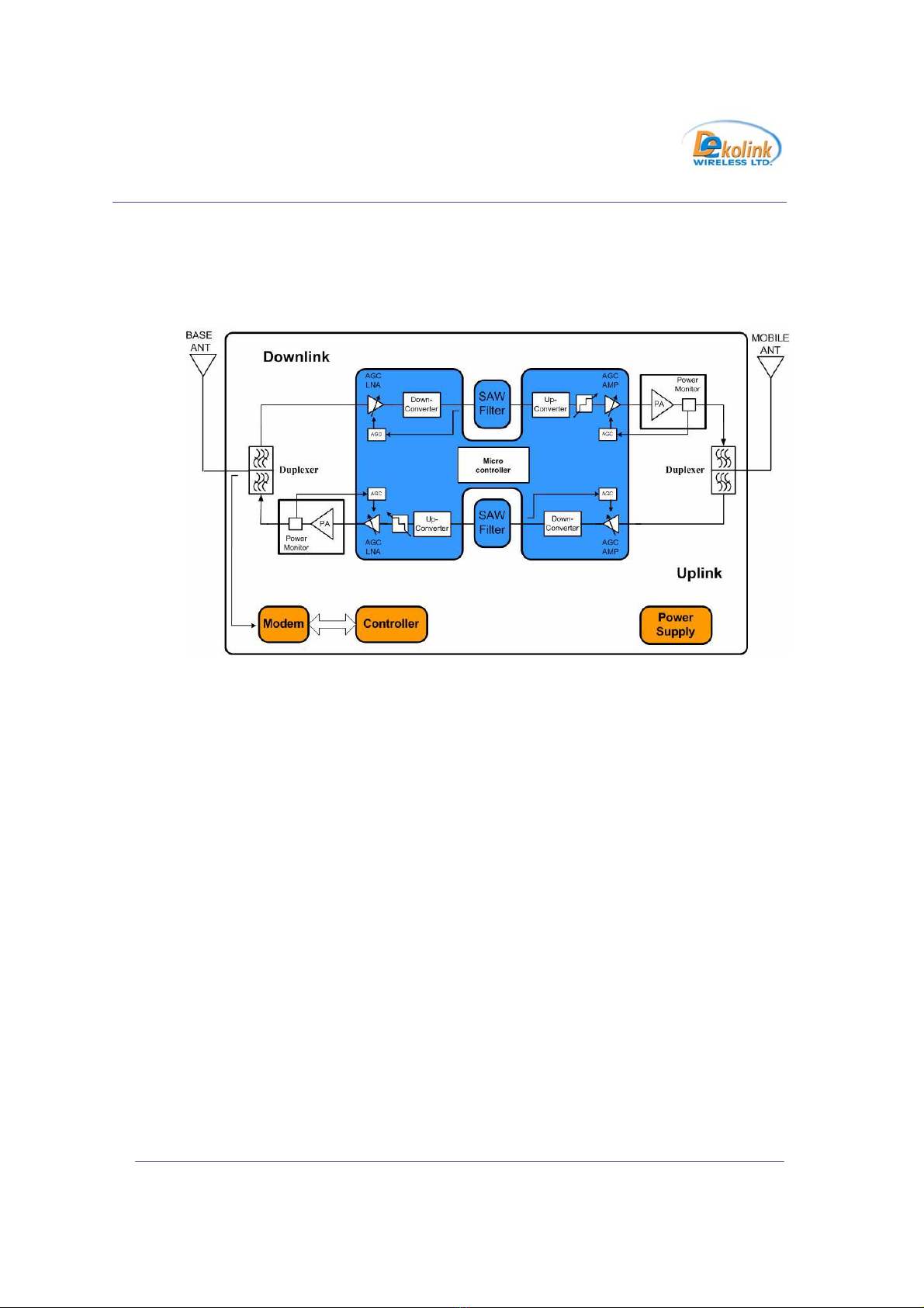
3. BLOCK DIAGRAM
Figure 1: Repeater RF Block Diagram
The block diagram showed in figure 1 illustrates the overall functionality of Dekolink
iDEN Repeater. Dekolink’s programmable iDEN Repeaters employ advanced
up/down conversion Intermediate Frequency (IF) Surface Acoustic Waves (SAW)
filtering architecture. This new technology offers distinct advantages over conventional
repeaters, when high adjacent selectivity and spectrum purity is required.
The Channeler Module (blue colored) consists of dual Radio Frequency (RF) Up/Down
Converter sub-modules for Downlink and Uplink paths. The Channeler amplifies the
received RF signals and converts them into an intermediate frequency (IF). The IF
outputs are connected to a SAW Filter. The IF outputs are converted back to the
original RF frequencies.
Cellular modem is an option for remote monitoring and control repeater parameters.

REPEATER OVERVIEW
Dekolink™—IDEN Repeater Hardware Manual 7
4. REPEATER OVERVIEW
This section provides information on the repeater’s components.
Figure 2: Repeater Overview
4
7
10
11
1
5
6
2
3
8
9

8Release 1.00
Authorized Customer Use
4.1.Components List
1. Channeler (Dual Up/Down Converter for Uplink and Downlink Paths)
2. Place for wireless Modem Unit
3. Control Box (CB04) Includes status LED and RS232/P3 connector for the local
connection with a PC/ Laptop
4. Downlink Power Amplifier
5. Duplexer to Mobile Antenna (high power)
6. Duplexer to Base Antenna (low power)
7. Power Supply
8. Coupler for Modem Antenna (for future remote connection).
9. Door Alarm Switch
10. Repeater Monitor Card (Includes Summarized Alarm LED)
11. Uplink Power Amplifier
4.1.1.Components Description
The following is a description of the main components of the Repeater.
4.1.2.Channeler
The Channeler Module consists of dual Radio Frequency (RF) Up/Down Converter sub-
modules for Downlink and Uplink paths. The Channeler amplifies the received RF
signals and converts them into an intermediate frequency (IF). The IF outputs are
connected to a SAW Filter. The IF outputs are converted back to the original RF
frequencies. The Channeler also has controllable attenuators (32 dB range in steps of
1dB)and a pre-amplifier for each path.
4.1.3. Repeater Monitor Module
The Monitor Module measures the current of the following elements of the Repeater:
Up/Down Converter, Uplink Power Amplifier, and Power Supply. It also senses the
Downlink output power. If a module fails, an appropriate report is sent to the Control
Box and the Summarized alarm red LED lights up.

REPEATER OVERVIEW
Dekolink™—IDEN Repeater Hardware Manual 9
4.1.4. Control Box
The Control Box is used to control and monitor all modules in the Repeater. It also
provides local or remote connection to a PC. (See Dekolink’s RMT User Guide for
more information.)
4.1.5. Power Supply
The power supply module has a wide range of allowed input power.
The output power provided to the repeater internal modules is 28VDC, 9VDC and
15VDC.
4.1.6. Duplexers
The duplexers isolate the transmit path from the receive path. The pass bandwidth of
the duplexer is the entire width of the Uplink band and the Downlink bands
respectively.
4.1.7. Power Amplifiers
The power amplifier is the final stage of both the Downlink and Uplink paths. The
Repeater includes Power Amplifiers with relatively high Third Order Intercept Point
(IP3) figures, thus allowing high output power while preserving high linearity of the
output signals.

10 Release 1.00
Authorized Customer Use
5. REPEATER FEATURES
5.1. Monitor And Control
The Dekolink Repeater Monitor Module monitors the DC functioning (DC Current and
Voltage Measurement) of the Repeater and provides local summarized feedback by an
alarm LED. The module provides the alarm statuses to the Control Box in the repeater. The
Control Box detects faults and controls the Repeater functions. The RMT software handles
alarm reporting and parameter transmissions to the repeaters’ outside world.
These functions are monitored and controlled in two ways:
• By an external PC through a serial interface connector on the Control Box.
• By a remote connection via a modem connected to the Control Box serial
interface. (Optional)
• The repeater operates from a power source of 110V/220 VAC. The maximum
consumption power is 120W
5.2. SALC (Smart ALC) Function
The Smart ALC optimizes gain factors while enabling iDEN repeater to remain
“transparent” to the network (both to the base stations and the mobile units).
Uplink and downlink balance is preserved. In previous repeaters there are separate
adjustments for the uplink and downlink. Here there is just one adjustment, manual
or automatic to both channels. Both channels have to be balanced for the proper
seamless integration of the repeater in the network. Unbalanced operation bares the
risk of reducing the dynamic range of the base station itself.
Reduction of isolation problems: .The proposed repeater will not oscillate.
Whenever the isolation drops for some reason the repeater will automatically sense
the oscillations and automatically reduce the gain in accordance with the new
isolation conditions. Once the isolation problem is solved the repeater will
automatically raise the gain again. All this is remote monitored and if so desired
remote controlled.

REPEATER FEATURES
Dekolink™—IDEN Repeater Hardware Manual 11
No adjustments are required: When installing the repeater, the standard procedure
for the technician is to tune the repeater to the desired isolation and gain values.
With SALC, the tuning procedure is accomplished automatically, thus saving
precious workmanship and equipment usage time for a “plug & play” foolproof
deployment.
The SALC periodically learns traffic conditions, avoiding the need to remember and
store the last state after power failure. Repeaters that blindly amplify the pilot code
(minimal transmission) of a certain base station might generate network problems
(unnecessarily increase the noise in a certain cell). By keeping the same gain for
pilot only transmissions as well as for full traffic situations, the Dekolink SALC
feature minimizes this effect.
SALC Summary, Conventional iDEN repeaters often interfere in the network when
strong traffic raises the repeater input signal level, which as a result turns on the
ALC algorithm of the system. Once under ALC, the conventional system is no
longer in its linear dynamic range, hence creating interferences in the cell shrinking
or expanding procedures. The Smart ALC solves this problem and thus there is no
need for adjustments. The repeater will not interfere with the network shrinking or
expanding processes and thus become “network friendly “.
5.3. Automatic Level Control (ALC) Function
The repeater has ALC functioning on both the Uplink and Downlink power amplifiers
that prevents saturation of the power amplifier. The amplifier has a directional coupler
and a detector that monitors the output power. When a high signal is received, the ALC
detects the amplitude and sends a feedback signal to a voltage variable attenuator that
attenuates the signal level so that the output power of the amplifier does not exceed the
preset limit. This level control ensures that the power amplifier operation stays within
the linear region only, thus preventing saturation and signal distortion.
Automatic Level Control protects the amplifiers from overloading and prevents the
system from generating spurious emissions. ALC limits the output power to a constant
value (Maximum output power). The output power is sampled, decoupled, rectified and
used to control the attenuator network in the RF modules.

12 Release 1.00
Authorized Customer Use
5.4. RF Gain Setting
The gain range is 59-90 dB and should be set via the RMT software according to the
received power at the Base/Donor antenna, required Output Power at Mobile antenna
and Isolation requirements. Use the Max Gain field for Downlink GAIN setting and the
Gain Delta fields to determine the GAIN difference between Uplink and Downlink path
(Uplink GAIN follows Downlink GAIN by “Delta” dB).
Note: When you set the gain to 60 dB the Maximum Output Power will degrade
due to overload input power the maximum input power you can inject is
–35 dBm.
It is recommended to set the Downlink path gain to a maximum of 12 dB below the
isolation between the Base antenna and the Mobile antenna.

SYSTEM INSTALLATION
Dekolink™—IDEN Repeater Hardware Manual 13
6. SYSTEM INSTALLATION
System installation includes the following steps:
Safety Instructions
Software Installation
Hardware Equipment Installation
System Initialization
System Activation
6.1. Safety Instructions
Note: Before starting the installation, read the following.
Follow all local safety regulations when installing the repeater.
Only qualified personnel are authorized to install and maintain the repeater.
When operating the repeater, it is recommended to keep its cover closed while
the power is on. Some maintenance tasks may require the repeater door to be
opened while the power is on. In such cases, perform the required tasks
carefully and remember to close the repeater cover/door when finished
Use a suitable mounting surface, such as a rigid wall.
Follow Electro-Static Discharge (ESD) precautions.
Before closing the repeater cover, make sure no wires are in the way.
Install the repeater close to the service area to improve the output power and
noise figure.
Use low loss cables to connect antennas to the repeater.
Install the repeater in a shielded, ventilated, and easy-to-reach area.

14 Release 1.00
Authorized Customer Use
6.2. Software Installation
Install the RMT Software from the supplied CD to your laptop. For detail instructions
refer to the Repeater Management Tool User Guide P/N: 300MB40080 page 4 to 8 -
Repeater Management Icon will appear on your desktop.
6.3. Hardware Equipment Instructions
Hardware Equipment Installation includes the following steps:
Repeater Installation
Base/Donor Antenna Installation
Mobile/Service Antenna Installation
AC Power Connection
PC/Laptop Connection
Figure 3: Typical Outdoor Hardware installation

SYSTEM INSTALLATION
Dekolink™—IDEN Repeater Hardware Manual 15
6.3.1. Repeater Installation
Mark the four drilling holes on the surface of the wall based on the mounting
holes on the repeater chassis.
Align the housing so that the mounting brackets fit into the holes in the wall.
Use tire bolts, hex-head bolts, and M8 washers screw the housing in firmly.
Note: These bolts and washers are NOT supplied with the repeater. Leave
enough room so that personnel can access the repeater even when its
door is open.
6.3.2. Base/Donor Antenna Installation
Choose an antenna with high side lobe attenuation that allows the maximum
isolation from the service/ mobile antenna.
Point the antenna in the direction of the base station to receive maximum input
power.
Make sure the antenna is in line of sight with the base site. You can raise the
antenna higher if necessary.
Measure all the necessary specifications of the antenna.
6.3.3. Mobile/Service Antenna Installation
Note: Before installing the Mobile/Service antenna, see the FCC regulations for
information regarding recommended distances between the antennas
and population centers.
Choose an antenna that allows the maximum isolation from the Base/Donor
Antenna.
Point the antenna in the direction of the service area you want to cover.
Measure all the necessary specifications of the antenna.

16 Release 1.00
Authorized Customer Use
Figure 4: Connection of the Repeater to the Laptop
Note: Antenna Isolation. For proper Repeater operation, Dekolink
recommends that the isolation between the Base/Donor and
Mobile/Service antennas will be at least 12 dB higher than the Repeater
set gain.
Note: Insure proper vertical or horizontal distance separation between Donor
and Service antennas
Note: AT THIS STAGE DO NOT CONNECT THE ANTENNAS TO
THE REPEATER. THEY WILL BE CONNECTED WITH RF
COAXIAL JUMPERS AT THE ACTIVATION STEP.
6.3.4. AC Power Connection
Plug in AC power cable to the repeater (the repeater automatically turns
on) . The green led at repeater front panel turns on as an indication of
power on (there is no On/Off switch).
6.3.5. PC/Laptop Connection
Connect the laptop to the repeater controller (CB 04) using the supplied RS232
Cable to P3-RS232 on the controller (Fig 4). The controller is located inside the
repeater box. Open the repeater door and identify the controller. Make sure that the
status led on the controller is blinking before you connect the cable.
Connect laptop serial port COM1 to the other side of the cable
RS232 Cable
Status Led

SYSTEM INSTALLATION
Dekolink™—IDEN Repeater Hardware Manual 17
6.4. System Initialization - Setting The Repeater Parameters
Activate the RMT from the Start menu or by double clicking the Repeater Management
icon on your desktop.
The following screen appears.

18 Release 1.00
Authorized Customer Use
Click the Temp Unit button
Click on the Connect button as shown in the figure below.
Once clicking the Connect button. The following window appears.
Select the mode of operation and click OK (Local or Remote) according to the
application:
• Local - PC connection to the repeater, for direct access.
• Remote - PC connection to the repeater via a modem (Optional).
After accessing the repeater, the Password window appears, enter the repeater’s
password and then click OK (the default password for the repeater is ”password”).
Connect Button
password
Table of contents
Other Dekolink Repeater manuals


