manuals.online logo
Brands
  1. Home
  2. •
  3. Brands
  4. •
  5. Reliable
  6. •
  7. Sewing Machine
  8. •
  9. Reliable 4300CW User manual

Reliable 4300CW User manual

Other Reliable Sewing Machine manuals

Reliable MSK-588 User manual

Reliable

Reliable MSK-588 User manual

Reliable MSK-8220B User manual

Reliable

Reliable MSK-8220B User manual

Reliable 7200DB User manual

Reliable

Reliable 7200DB User manual

Reliable MSK-8900M User manual

Reliable

Reliable MSK-8900M User manual

Reliable MSK-1341B User manual

Reliable

Reliable MSK-1341B User manual

Reliable MSK-8400B User manual

Reliable

Reliable MSK-8400B User manual

Reliable MSK-373N User manual

Reliable

Reliable MSK-373N User manual

Reliable 2700SZ User manual

Reliable

Reliable 2700SZ User manual

Reliable 8100BS Owner's manual

Reliable

Reliable 8100BS Owner's manual

Reliable MSK-755H User manual

Reliable

Reliable MSK-755H User manual

Reliable 5400SW User manual

Reliable

Reliable 5400SW User manual

Reliable 7100DB User manual

Reliable

Reliable 7100DB User manual

Reliable MSK-1541S User manual

Reliable

Reliable MSK-1541S User manual

Reliable MSK-755 User manual

Reliable

Reliable MSK-755 User manual

Reliable MSK-8210M User manual

Reliable

Reliable MSK-8210M User manual

Reliable MSK-8600B User manual

Reliable

Reliable MSK-8600B User manual

Reliable 5600TW Operating and maintenance manual

Reliable

Reliable 5600TW Operating and maintenance manual

Reliable MSK-8420B User manual

Reliable

Reliable MSK-8420B User manual

Reliable MSK-3316N User manual

Reliable

Reliable MSK-3316N User manual

Reliable 2200SZ User manual

Reliable

Reliable 2200SZ User manual

Reliable MSK-8400BL-18 User manual

Reliable

Reliable MSK-8400BL-18 User manual

Reliable 2400SZ User manual

Reliable

Reliable 2400SZ User manual

Reliable 4400SW User manual

Reliable

Reliable 4400SW User manual

Reliable Barracuda 2000U User manual

Reliable

Reliable Barracuda 2000U User manual

Popular Sewing Machine manuals by other brands

Brother PE-180D Service manual

Brother

Brother PE-180D Service manual

Singer 569U1100 Operator's guide

Singer

Singer 569U1100 Operator's guide

ELNA 2002 instruction manual

ELNA

ELNA 2002 instruction manual

Siruba DL7200D-NM1 Instruction book

Siruba

Siruba DL7200D-NM1 Instruction book

Silver Viscount 9500e instruction manual

Silver

Silver Viscount 9500e instruction manual

Pfaff 3588-05/020 instruction manual

Pfaff

Pfaff 3588-05/020 instruction manual

JUKI DDL-9000A instruction manual

JUKI

JUKI DDL-9000A instruction manual

Pfaff 284 Instruction book

Pfaff

Pfaff 284 Instruction book

Kenmore 385. 19000 owner's manual

Kenmore

Kenmore 385. 19000 owner's manual

Brother FD4-B271 instruction manual

Brother

Brother FD4-B271 instruction manual

Brother Computerized Embroidery Machine Operation manual

Brother

Brother Computerized Embroidery Machine Operation manual

Husqvarna Viking Designer SE user guide

Husqvarna Viking

Husqvarna Viking Designer SE user guide

Singer 645 owner's manual

Singer

Singer 645 owner's manual

Riccar RL634DE user manual

Riccar

Riccar RL634DE user manual

ZOJE ZJ9800 Operation manual

ZOJE

ZOJE ZJ9800 Operation manual

Siruba C007JP Instruction book

Siruba

Siruba C007JP Instruction book

IKEA SY user guide

IKEA

IKEA SY user guide

Pfaff 571 instruction manual

Pfaff

Pfaff 571 instruction manual

manuals.online logo
manuals.online logoBrands
  • About & Mission
  • Contact us
  • Privacy Policy
  • Terms and Conditions

Copyright 2025 Manuals.Online. All Rights Reserved.

INDUSTRIAL SEWING MACHINE INSTRUCTION MANUAL
4300CW
CONTENTS
1.Brief instruction..............................................1
2 . M a i n s p e c i f i c a t i o n . . . . . . . . . . . . . . . . . . . . . . . . . . . . . . . . . . . . . . . . . . 1
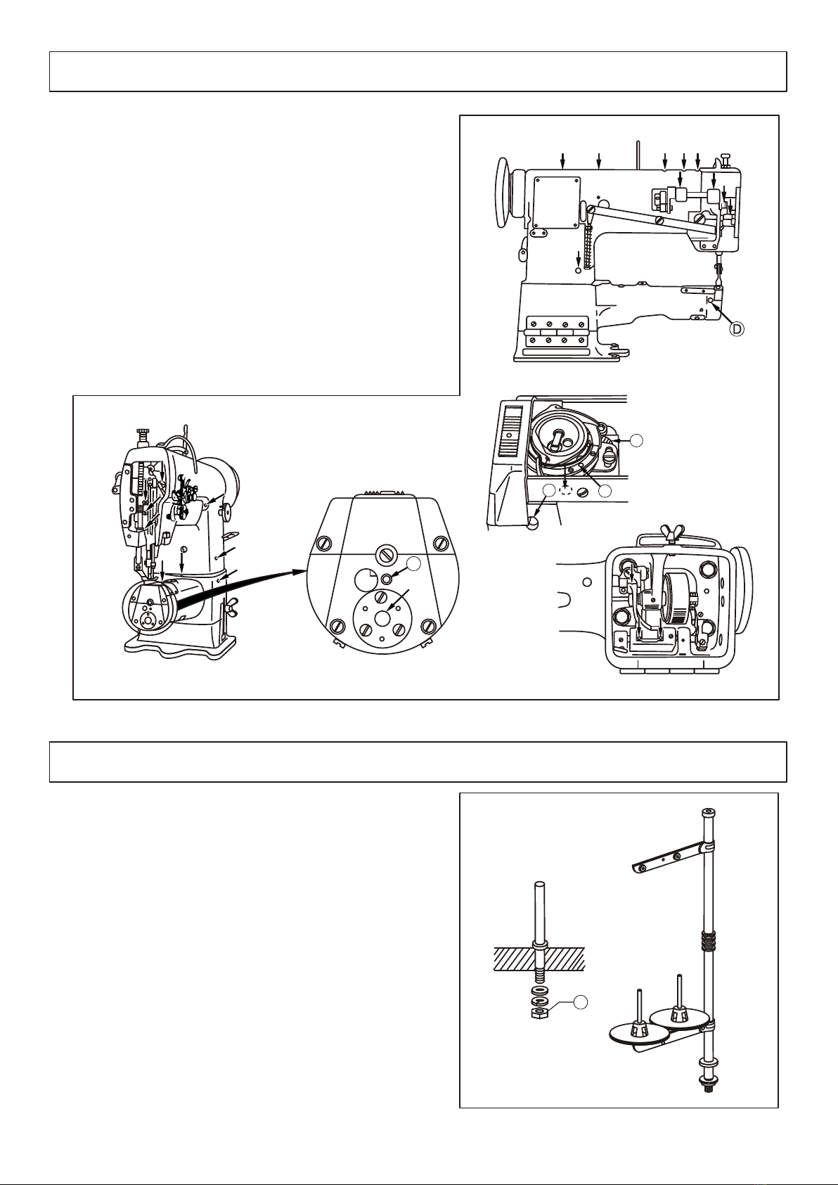
3.Operation preparation..............................................1
4. In st al li ng th e kn ee li ft er me ch an is m. .. .. .. .. .. .. .. .. .. .. .. .. .. .. .. .. .. .. .. .. .1
5.Lubrication.................................................2
6 . I n s t a l l i n g t h e t h r e a d s t a n d . . . . . . . . . . . . . . . . . . . . . . . . . . . . . . . . . . . . . . . . . . . . . . 2
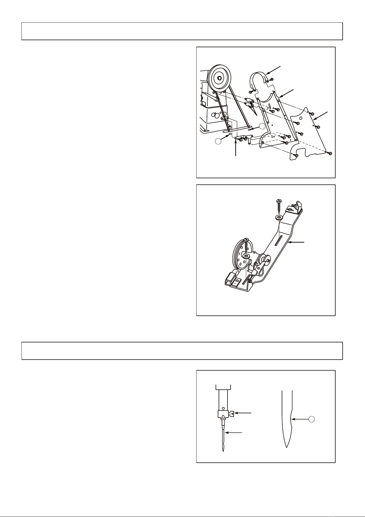
7. In st al li ng th e be lt co ve r an d bo bb in wi nd er .. .. .. .. .. .. .. .. .. .. .. .. .. .. .. .. .3
8 . I n s t a l l i n g t h e n e e d l e . . . . . . . . . . . . . . . . . . . . . . . . . . . . . . . . . . . . . . . . . . . . . . 3
9 . I n s t a l l i n g t h e b o b b i n c a s e . . . . . . . . . . . . . . . . . . . . . . . . . . . . . . . . . . . . . . . . . . . . 4
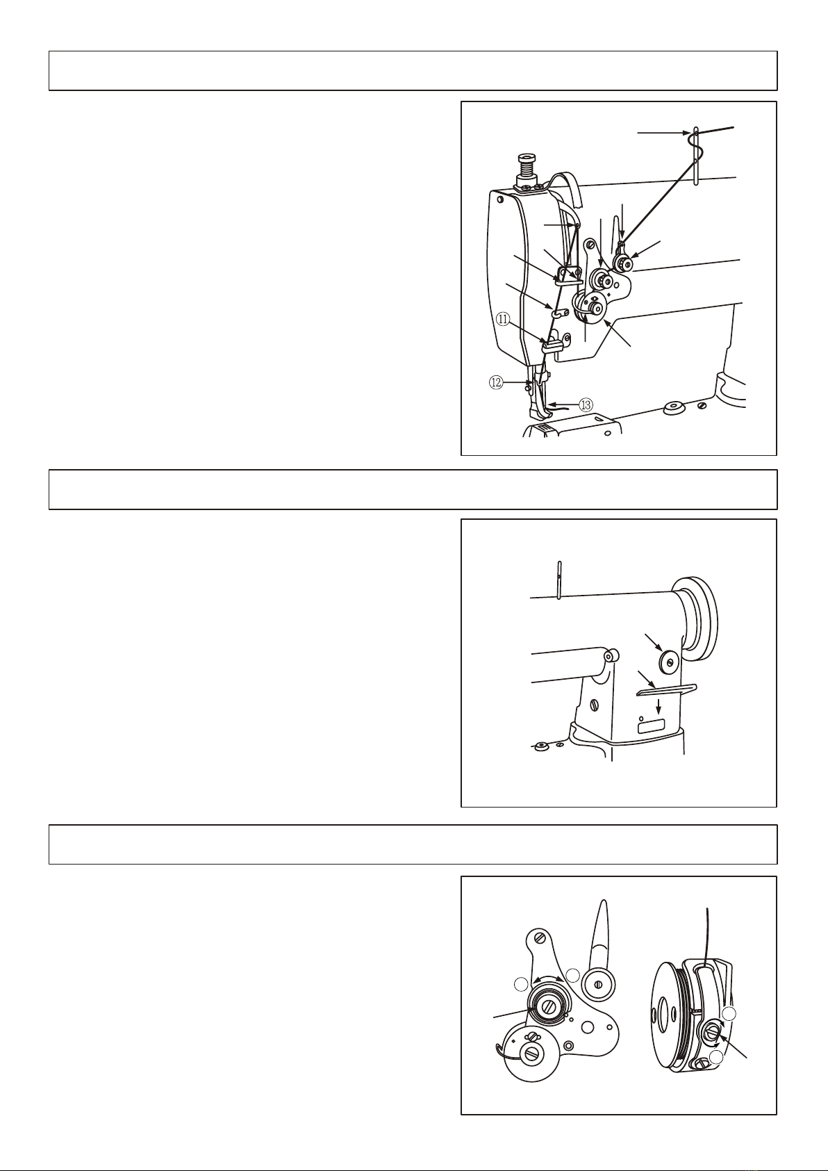
1 0 . W i n d i n g t h e b o b b i n t h r e a d . . . . . . . . . . . . . . . . . . . . . . . . . . . . . . . . . . . . . . . . . . . . 4
1 1 . P u t t h e b o b b i n i n t o b o b b i n c a s e . . . . . . . . . . . . . . . . . . . . . . . . . . . . . . . . . . . . . . 4
1 2 . T h r e a d i n g t h e n e e d l e t h r e a d . . . . . . . . . . . . . . . . . . . . . . . . . . . . . . . . . . . . . . . . . . . . . . . 5
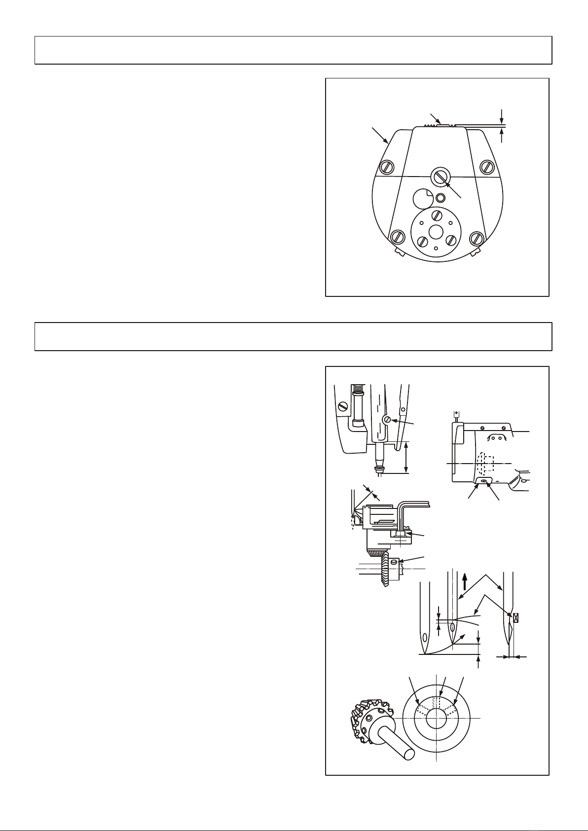
1 3 . A d j u s t i n g t h e s t i t c h l e n g t h . . . . . . . . . . . . . . . . . . . . . . . . . . . . . . . . . . . . . . . . . . . . 5
1 4 . T h r e a d t e n s i o n . . . . . . . . . . . . . . . . . . . . . . . . . . . . . . . . . . . . . . . . . . . . . . . 5
1 5 . T h r e a d t a k e - u p s p r i n g . . . . . . . . . . . . . . . . . . . . . . . . . . . . . . . . . . . . . . . . . . . . . . . 6
1 6 . A d j u s t i n g t h e p r e s s u r e o f p r e s s e r f o o t . . . . . . . . . . . . . . . . . . . . . . . . . . . . . . . . . . . . . . . . . 6
17.Adjusting the height of presser foot.........................................6
1 8 . A d j u s t i n g t h e h e i g h t o f f e e d d o g . . . . . . . . . . . . . . . . . . . . . . . . . . . . . . . . . . . . . . . 7
1 9 . A d j u s t i n g t h e n e e d l e a n d h o o k . . . . . . . . . . . . . . . . . . . . . . . . . . . . . . . . . . . . . . . . . 7
20.Adjusting the needle guard plate.....................................8
21.Adjusting the inner hook guide.......................................8
2 2 . A d j u s t i n g t h e l e n g t h w a y s p o s i t i o n o f n e e d l e b a r f r a m e . . . . . . . . . . . . . . . . . . . . . . . . . . . . . . . . . . 8
2 3 . S a f e t y c l u t c h d e v i c e . . . . . . . . . . . . . . . . . . . . . . . . . . . . . . . . . . . . . . . . . . . . 9
2 4 . R e l o a d i n g t h e t i m i n g b e l t . . . . . . . . . . . . . . . . . . . . . . . . . . . . . . . . . . . . . . . . . . . 9
25.Ttrouble and remedy...................................10
1.Casting components..........................................11-12
2 . U p p e r s h a f t a n d t h r e a d t a k e - u p l e v e r c o m p o n e n t s . . . . . . . . . . . . . . . . . . . . . . . . . . . . . . . . . . . . 1 3 - 1 4
3 . N e e d l e b a r a n d h o o k d r i v i n g s h a f t c o m p o n e n t s . . . . . . . . . . . . . . . . . . . . . . . . . . . . . . . . . . . . 1 5 - 1 6
4 . P r e s s e r f o o t c o m p o n e n t s . . . . . . . . . . . . . . . . . . . . . . . . . . . . . . . . . . . . . . . . . . 1 7 - 1 8
5 . U p p e r f e e d m e c h a n i s m c o m p o n e n t s . . . . . . . . . . . . . . . . . . . . . . . . . . . . . . . . . . . . . . . . . 1 9 - 2 0
6 . L o w e r f e e d m e c h a n i s m c o m p o n e n t s . . . . . . . . . . . . . . . . . . . . . . . . . . . . . . . . . . . . . . . . 2 1 - 2 2
7.Thread tension components.......................................23-24
8. Be lt co ve r an d bo bb in wi nd er co mp on en ts .. .. .. .. .. .. .. .. .. .. .. .. .. .. .. .. .. 25 -2 6
9 . K n e e l i f t e r c o m p o n e n t s . . . . . . . . . . . . . . . . . . . . . . . . . . . . . . . . . . . . . . . . . 2 7 - 2 8
1 0 . A c c e s s o r i e s . . . . . . . . . . . . . . . . . . . . . . . . . . . . . . . . . . . . . . . . . . . . . . . . . . . . . . . . . . . . . . . . . . . . . . . . . . . . . . . . . . . . . . 2 9 - 3 0
Operation instruction
Parts list
3. Opera ti on pr ep arati on
1. Brief i ntrod uc tion 1. Main sp ec ifi ca tion
T h i s c y l i n d e r b e d s e w i n g m a c h i n e a d o p t s s i n g l e
n e e d l e , s l i d e t y p e t h r e a d t a k e - u p l e v e r , a n d v e r t i c a l l a r g e
h o k . U p p e r a n d l o w e r s h a f t s a r e d r i v e n b y s y n c h r o n i z e d
t o o t h e d b e l t . C o m p o u n d f e e d b y f e e d d o g , n e e d l e a n d
walk i n g f o o t ; a n d high pr e sser fo o t s t r o k e a n d l i f t e r ass u r e
i t s h i g h s w e i n g h e a v y a b i l i t y a n d e a s y f o r s e w i n g mu l t i -
l a y e r l e a t h e r a n d u n e v e n m a t e r i a l s . S a f e t y c l u t c h d e v i c e
also ass ures safe opera tion .
I t s w i d e l y u s e d f o r s e w i n g l e a t h e r p r o d u c t s , s u i t c a s e s ,
s h o e s a d c a p s . E s p e c i a l l y , i t s c y l i n d e r b e d i s s u i t a b l e f o r
sewing vari ous arc and curved materi als. .
2000s.p.m
MSK-1341B
6mm
33.36mm
6.5mm by hand
15mmby knee
Slide type
Large hook
Dp×1 7 1 4"~24"(stan d ard23")
Oiled by hand
400 W ( special for sew i ng machine 2P)
Medium,heavy,extra heavy
weight materials
Befre first operate the machine,please clean the machi ne thoroughly in order to weed out the
dust and frlly lubricate the machine.
Please confirm if the power will be used is suitable for the designed voltage.
The rotating direction of the machine is counter-clock w ise when observed face to the hand wheel.
Before turn over the machine head,please take down the kne e lifter chain hook.
Before trial running,please take down the bobbin and needle.
Please control the sewing speed under 1800s.p.m within t he first operation month.
Only after the machine stops,then the hand wheel can be operated.
4. Insta ll ing t he k nee lif ter mec hanis m(Fig .1)
When use the knee lifte r pedal,plea se use the screw
to fi x the knee lifter l ever .
Knee lifter leaver and screw are packed in the a c-
cess ory carton.



272mm
61mm
100.5mm
33.5mm
① ②
Max.sewing s pee d
Max.stitch l eng th
Needle bar str oke
Presserfoo t lif t
height
Thread take- up le ver
Hook
Needle
Lubrication
Motor Power
Abblication
To center of V-belt
5. Lubri ca tion( Fig.2 )
1.Before runni ng,please fill the oil at the places as
arrow shown.
2.Lubricatin g the hook and hook shaft saddle.
Move the bed slide ,fill the oil int the hole A two or
three drops ever y day,fill the oil into the felt B four
or five drops.
3.Lubricatin g the feed dog support
Before running ,please fill the oil into holes C,D,E
two or three drops .
6.Installing the thread stand(Fig.3)
C
E
B
A
The th read stand should be lo cated on the righ t backside
of the t able,then tighten t he nut C.
C
7.Installing the belt cover and bobbin winder(fig.4、5)
1.Install the belt cover support column into the screw
hole;
2.Install the belt cover support plate on the machine
casting;
3.Install the belt cover on the belt cover support
column and the belt cover support plate;
4.Install the bobbin winder into the cover and
adjust it to the proper position;
5.Fix the bobbin winder on the table;
6.Install the V-belt on the hand wheel,the n install the
belt cover and belt cover .
①
②
③
①
⑥ ③
⑥
④ ⑤
1.T urn off the pow er;
2.T urn the han d whe el to lif t the nee dle bar to its
hig hes t pos iti on;
3.l oos en the nee dle set scr ew ,an d mak e the nee dle
gro ove Ato the rig ht sid e;
4.I nse rt the nee dle sha nk unt il to the bot tom of the
nee dle bar soc ket ;
5.T igh ten the scr ew .
②
①
②
8. Insta ll ing t he n eedle (fig .6 )
①
②
A
①
②
③
④
⑤
⑥
B
A
9. Insta ll ing t he b obbin c ase(F ig.7)
1.Op en the hook cover,put t he bobbin and bob bin
Case i nto the hook;
2.pu t the bobbin case on the ho ok driving shaf t,then
lay do wn the hook cover.
10 .Wind in g the b ob bin thr ead(F ig.8)
1.T hre ad as fol low ing ord er A,B ,C, the n win d the thr ead
aro und bob bin sev era l cir cle s;
2.P res s dow n the bob bin pre ss pla te ,th e win din g
pul ley wil l be tou che d wit h the V-b elt ;
3.w ind ng amo unt can be adj ust ed by the scr ew ,th e
opt imu m cap aci ty of bob bin thr ead is fil l abo ut 80%
of bob bin out sid e dia met er. Tur n the scr ew clo ckw ise
to inc rea se the win din g amo unt ,co ntr ary ,to dec rea se
the amo unt ;
4.I f the thr ead is not nea t,p lea se mov e the bra cke t
to adj ust is;
5.W hen the win din g is ove r, the bob bin pre ss pla te
wil l be loo se and the bob bin win der wil l sto p aut oma -
tic all y.
①
②
③
①
11 .Put th e bobbi n in to bobb in case (fig. 9)
1.Dr aw the tip of bobbi n thread to th e right ,then put the
bobbin into bobbin case;
2.Dr aw the bobbin thre ad through th e slit on th e
bobb in case,then pass through the t hread tension
spri ng,finally,draw the thread ou t of the slit .
Remi nder:if the bobbi n is put corre ctly,then draw the
bobb in thread as A,the bobbin will r otates as B.
①
②
A
B
C
①
②
③
①
②
B
A
12 .Thre ad ing t he n eedle t hread (fig. 10)
P o s i t i o n t h e n e e d l e b a r o n i t s h i g h e s t , d r a w t h e t h r e a d
f r o m t h e t h r e a d s t a n d a n d t h r e a d a s s h o w n o r d e r
a c c o r d i n g t o F i g . 1 0 .
13 .Adju st ing t he s titch l ength (Fig. 11)
Turn the stitch dial co unter-clock wise or clockwise to
adju st the stitch leng th. The figur e on the dial is the
stit ch length.(mm)
Reve rse feed stitchin g
1.Pr ess the feed leave rdownward;
2.Wh en press the feed l ever downw ard, the feed ing is
reve rse;
3.Re lease the feed lev er, the machi ne recovers norma l
feed ing again.
②
14 .Thre ad t ens io n(Fig .12)
1. Ad ju st in g th e te ns io n of ne ed le th re ad
Tu rn th e te ns io n ad ju st me nt nu t cl oc kw is e( A
di re ct io n) to in cr ea se th e te ns io n of ne ed le th re ad ;t ur n
th e nu t co un te r- cl oc kw is e( B di re ct io n) to de cr ea se th e
te ns io n.
2. Ad ju st in g th e te ns io n of bo bb in th re ad
Tu rn th e te ns io n ad ju st me nt nu t co lc kw is e( C di re c-
ti on )t o in cr ea se th e te ns io n of bo bb in th re ad ; tu rn th e
nu t co un te r- cl oc kw is e( D di re ct io n) to de cr ea se th e
te ns io n.
①
②
①
②
③
④
⑤
⑥
⑦
⑧
⑨
⑩
6
5
0
4
3
2
1
①
②
BA
①
②
D
C
15 .Thre ad t ake -u p sprin g(fig .13)
1. Ad ju st in g th e th re ad ta ke -u p sp ri ng st ro ke
a. Lo os en th e sc re w ,a nd mo ve th e di sc le ft wa rd
or ri gh tw ar d;
b. Mo ve th e di sc ri gh tw ar d to in cr ea se th e sp ri ng
st ro ke ,c on tr ar y, to de cr ea se th e sp ri ng st ro ke .
2. Ad ju st in g th e te ns io n of th re ad ta ke -u p sp ri ng
Ti gh te n th e nu t ,t ur n th e sp ri ng sh af t co un te r-
co lc kw is e to in cr ea se th e te ns io n, co tr ar y, to de cr ea se
th e te ns io n. Pl ea se us e a sc re wd ri ve r to ro ta te th e sp ro ng
sh af t to ge t th e re qu ir ed te ns io n.
①
② ③
④
⑤
16 .Adju st ing t he p ressu re of pre sser fo ot(Fi g.14)
Adj ust the pre sse r foo t pre ssu re acc ord ing to the mat er-
ial s.( the sta nda rd hei ght of pre ssu re adj ust men t scr ew
is 25m m).
1.T urn the scr ew clo ckw ise (A dir ect ion )to inc rea se
the pre ssu re, con tra ry, tur n the scr ew cou nte r-
clo ckw ise (B dir ect ion )to dec rea se the pre ssu re,
2.A fte r the pro per pre ssu re is got ,ti ght en the nut .
①
①
①
②
17 .Adju st ing t he h eight o f press er foot (fig. 15)
1.Th e optimum fixed position of presser foot is to adjust
The presser foot to the “1/8”indication line on
The feed crank.
Loosen the nut and adjust the cam link assembl ing
position.
a.At he highest position A, the max .Presser foot
Vertical stroke is got;
b.At the lowe st position B, the mi n. Pr esser foot
vertical stroke is got.
2.Us ually, the srtoke of outer presser foot is same as that of
the inner presser foot.
A.Loosen the screw ;
b.When the thread take-up lever is at its highest
position,lay down the presser bar lever;
c.Ad just the feed crank to leftward(A directon)
to increase the presser foot stroke.contrary,adjust
the feed crank to rightward (b direction) to
decrease the presser foot stroke.
①
②
③
③
①②
③
④
⑤
Standard
25mm
BA
①
②
①
B
AAA
②③
B
A
18 .Adju st ing t he h eight o f feed do g(Fig .16)
The s tandard position of feed dog i s 1mm higher t han the
surf ace of throat plat e .
Plea se adjust it as fol owing order a ccording to sewin g
requ irement or after c hange a new fe ed dog:
1.Pl ease confirm the h ighest posit ion of feed dog;
2.loosen the screw ;
3.Th e height can be adj ustd by turni ng eccentric pin( P22).
4.Af ter the requred he ight is got, t ighten the screw .
①
②
③
③
19 .Adju st ing t he n eedle a nd hook (Fig. 17)
1.Adjust the stitch dial to figure“3”
2.Turn the hand wheel to lower the needle bar to its
lowest position, and loosen the scrwe ;
3.confirm the standard height of needle bar:Lift the
needle bar up to 2.4mm from its lowest position, there
should be1.7mm clearance hetween upside of needle
hole and the tip of hook blade ;the lowest position
of needle bar is that there is a clearance of 55.2mm
from the bottom of needle bar rocking frame to the
bottom of needle bar.
4.Loosen the screw ,move the gear cover , and
loosen the screw and screw ;
5.Loosen the screw ,move the hook shaft saddle left-
ward or rightward,assure the clearance between the
tip of hook blade and needle is 0~0.5mm, after
finish, tighten the screw;
6.Make the tip of hook blade align with the center of
needle bar,then tighten the screw ;
7.Turn the hand wheel clockwise, tighten the screws
alternately.
①
⑥
③ ②
④ ⑧
⑤
⑦
④
⑧
1 mm
①
②
③
②③
④ ⑧⑧
①
55.2mm
④
⑤
0~0.05mm
⑥
⑦
1.7mm
2.4mm
0~0. 05mm
20 .Adju st ing t he n eedle g uard pl ate(F ig.18 )
Afte r changing hook , p lease confir m the position of
need le guard plate. Th e standard po sition of needle g uard
plat e is that needle gu ard plate is touched with the
flan k side of needle slightly, if not,bend the plate and
adju st the position:
1.If the needle guard p late bends in ward, please a dju st
the p late outward with a screwdrive r;
2.If the needle guard p late bends ou tward,please adj ust
the p late inward with a screwdriver ;
②
①
0~0.05mm
①
②
21 .Adju st ing t he i nner ho ok guid e(Fig .19)
1.Tu rn the hand wheel t o make the inn er hook guide
reac h its final positi on;
2.Tu rn the bobbin case as the direct ion shown by arrow
Bunt il to the slit of th roat plate ;
3.Lo osen the screw , the move the ad justing plat e
of in ner hook guide as a rrow shown di rection,assure
the c learance between the inner hoo k guide and the
bobb in case flange is a bout 0.1~0.1 5mm.
①
④
⑤ ⑥
0.1~0.15mm
①
②
③
④
⑤
⑥
A
BB
B
22 .Adju st ing t he l ength ways po sitio n of need le bar fr ame(F ig.20 )
1.Adjusting the relationship between the inner presser
foot bar and pressing bar:
a.Adjust the stitch dial to min.figure;
b.Loosen the screw , adjust the distance between
theinner presser foot bar and pressing bar to
7.5mm.
Note:Dont make any clearance at axis direction of
needle bar frame.
2.Adjusting the relationship between the feed dog and
needle bar:
a.Adjust the stitch dial to min.figure;
b.Loosen the screw ;
c.Adjust the position of feed dog to make the needle
ali gn with the center of needle hole on the throat
plate(towards to the operator slightly).
①
③
③
①
②
7.5m m