Reliable DDX-LP PrePak Maintenance manual

Reliable Automatic Sprinkler Co., Inc., 103 Fairview Park Drive, Elmsford, New York 10523
Model DDX-LP PrePak System
2” (50mm), 21
/
2” (65mm),
3” (80mm), 4” (100mm),
6” (150mm) & 8” (200mm)
Bulletin 748 July 2019
Instructions for
Installation, Operation,
Care and Maintenance
Low Pressure Dry-Pipe System
10 psi - 26 psi (0.7 bar - 1.8 bar)
Recommended System Pressure
General Description
The Reliable Model DDX-LP PrePak (Sizes 2” (50mm),
2½” (65 mm), 3” (80 mm), 4” (100 mm), 6” (150mm) and
8” (200mm)) is a completely self-contained, supervised dry
pipe system that can be readily installed within a floor space
of less than 7 square feet (0.65 square meters). Refer to Fig.
1 for cabinet dimensions. Installation of the DDX-LP PrePak
requires just three piping connections: the water supply, the
sprinkler system and the drain. Reference locations of these
piping connections are shown in Fig. 1. One electrical sup-
ply connection is required. Note: The Model DDX-LP PrePak
is available with an optional 115V VAC (60Hz) air compres-
sor.
Full assembly drawings for the units are available on the
Reliable Automatic Sprinkler Company website (www.reli-
ablesprinkler.com).
The heart of the Reliable Model DDX-LP PrePak is the
Model DDX-LP Dry Pipe Valve. The Reliable Model DDX-LP
Dry Pipe Valve is a hydraulically operated, differential-type
valve designed for use as a primary control valve in a low
pressure dry pipe valve system. The trim set used with the
Model DDX-LP Dry Pipe Valve contains the Reliable Model
LP Dry Pilot Actuator releasing device. This Actuator allows
the system air or nitrogen pressure to be considerably less
than the water supply pressure (see Table A). The following
benefits are a direct result of lower air pressure:
1. In refrigerated area systems, lower air pressure de-
creases the possibility of ice plugs that could impede
or prevent the flow of water to fire sprinkler heads in
the event of fire.
2. Lower air pressure allows for smaller capacity, lower
cost dehydration equipment, where required.
3. Lower air or nitrogen pressure can reduce water de-
livery time when the system actuates, and in some
cases, may eliminate the need for an accelerator.
4. For systems supplied with nitrogen, low supervisory
pressure reduces the quantity of nitrogen required to
maintain the system pressure.
Note: Photograph is for illustrative purposes only.

2.
When using the Reliable DDX-LP PrePak the sprinkler sys-
tem is pressurized with air provided by the optional factory-
installed air compressor or on-site Nitrogen supply and is
monitored by a system pressure switch. If bottled Nitrogen is
being used as the supervisory gas, an optional Nitrogen Kit
is available. This kit contains a regulator and an additional
pressure switch that is used to monitor any low pressure
conditions that may arise due to having a limited Nitrogen
supply. When using Nitrogen, the primary supervisory gas
should be the Nitrogen (not standard air) due to moisture
concerns (i.e. freezing conditions). The optional factory-
installed air compressor should be utilized merely for initial
fill and make-up air when the Nitrogen supply is not active.
Note: Compressed air is not to be considered dry air and
may create ice plugs in the sprinkler system piping.
When a fire sprinkler operates, there will be a loss of air or
Nitrogen pressure in the sprinkler system piping which will
cause the Model LP-Dry Pilot Actuator to open. The opening
of this device allows the Model DDX-LP PrePak valve to flow
water into the system piping.
A Model B Hydraulic Manual Emergency Releasing sta-
tion is standard equipment in the Reliable DDX-LP PrePak. It
consists of an aluminum nameplate mechanically attached
to a ball valve. The valve handle in its OFF position is guard-
ed against accidental turning to the ON position (and sys-
tem discharge) by a nylon cable tie provided with the DDX-
LP PrePak assembly. The cable tie is designed to allow, in
case of an emergency, forceful turning of the valve handle
to the ON position.
Listings and Approvals
1. Underwriters Laboratories, Inc. Listed and Certi-
fied for Canada (cULus) as an assembled unit in the
“Special System Water Control Valves Assembled
Units” category, (VKYL).
2. Factory Mutual Approved as a Dry Pipe Sprinkler
System.
Technical Data
1. The Reliable Model DDX-LP PrePak is rated for a mini-
mum water supply pressure of 20 psi (1.4 bar) and a
maximum water supply pressure of 250 psi (17.2 bar).
Note: 1 bar = 100 kPa.
2. Friction loss, expressed in equivalent length of Sched-
ule 40 pipe and based on Hazen-Williams Formula is:
System Size Equivalent Length
2” (50 mm) 19.4 ft (1.3 m)
2½” (65 mm) 24.5 ft (1.8 m)
3” (80 mm) 28.9 ft (3.8 m)
4” (100 mm) 32.8 ft (17.7 m)
6” (150 mm) 54.7 ft (21.8 m)
8” (200 mm) 79.3 ft (24.2 m)
The equivalent length in the table above includes the
Model DDX-LP PrePak valve, supply manifold tee, sup-
ply side control valve, and the section of pipe above the
Model DDX-LP PrePak valve.
3. Shipping Weight:
System Size Weight
2” (50 mm), 2½” (65 mm)
& 3” (80 mm)
554 lb. (252 kg)
4” (100 mm) 710 lbs (322 kg)
6” (150 mm) 800 lbs (363 kg)
8" (200mm) 1350 lbs (531kg)
4. Refer to Figure 1 for dimensions.
The following is a list of Technical Data Bulletins which de-
scribe the valves and devices which are used in the system:
Device Reliable Bulletin #
(unless otherwise noted)
Model DDX-LP PrePak Deluge
Valve Reliable Bulletin 519
Model DDX-LP Dry Pipe Valve Reliable Bulletin 338
Low Air Pressure Switch Potter, 5401564
Alarm Pressure switch Potter, 5400928
Nitrogen Pressure Switch Potter, 5400930
Mechanical Sprinkler Alarm Reliable Bulletins 612/613
Desiccant Dryer Wilkerson Catalog 9EM-TK-190-4
Installation Requirements
The automatic sprinklers utilized with the DDX-LP PrePak
must be UL and/or ULC Listed or FM Approved, as appli-
cable.
The steel enclosure and all the interconnecting piping
must be located indoors in a readily visible and accessible
location and in an area that can be maintained at a mini-
mum temperature of 40°F (4°C). Note: Heat tracing is not
permitted. The Model DDX-LP PrePak PrePak operation is
controlled by the Model LP Dry Pilot Actuator. The introduc-
tion of moisture into the system piping exposed to freezing
temperatures can create ice blockage, which could prevent
proper system operation. As a minimum, the air supply
should be taken from the area of lowest temperature within
the protected area. The air supply system must be carefully
designed to prevent plugging by frost deposits. Special re-
quirements, such as those in FME&R “Installation Guidelines
for Refrigerated Storage” may need to be incorporated.
Hydrostatic Testing of DDX-LP PrePak Valves and
DDX-LP PrePak Systems
As required by NFPA 13, fire sprinkler systems with work-
ing pressures up to and including 150 psi are to be hydro-
statically tested at a water pressure of 200 psi. Fire sprinkler
systems with working pressures above 150 psi are required
to be hydrostatically tested at 50 psi above the system work-
ing pressure. In addition to the hydrostatic tests described
above, dry pipe systems require an additional low pressure
air test.
In some cases, hydrostatic testing (in accordance with the
NFPA 13 requirements noted above) will result in pressures

3.
Fig. 1

4.
that exceed the working pressure of the valve and trim kit for
the two-hour test period.
The valve and applicable trim kit have been tested, ap-
proved and listed under these conditions and as such, hy-
drostatic testing in accordance with NFPA 13 is acceptable.
In addition, the clapper can remain in the closed position
and the trim kit need not be isolated, as each has been de-
signed to withstand hydrostatic testing as required by NFPA
13.
Subjecting the valve and trim to pressures higher than
their rating is limited to the hydrostatic test as referenced
by NFPA13. It does not address the occurrence of a “wa-
ter hammer” effect, which may damage the valve. A “water
hammer” in the water supply piping of the valve can cre-
ate pressures in excess of the rated pressure and should
be avoided by all necessary means. This condition may be
created from improper fire pump settings, underground con-
struction work, or an improper venting of trapped air in the
water supply piping.
System Supervisory Pressure Requirements
The DDX-LP PrePak includes gauges indicating the air/
nitrogen and water pressures on the Model DDX-LP sys-
tem. Table A specifies the air or nitrogen pressure to be
maintained in the sprinkler system piping based on the wa-
ter supply pressure. The factory installed Pressure Mainte-
nance Device in the unit automatically regulates makeup air
or nitrogen flow to maintain pressure with normal leakage
from system piping, while restricting the flow of makeup air
or nitrogen to the system. Please note that when the optional
Model B1 Accelerator is to be utilized to expedite water-de-
livery time, the air or nitrogen pressure must be not less than
15 psi (1.0 bar).
Table A
Water Pressure
psi (bar)
Supervisory Air or Nitrogen Pressure in
Sprinkler System, psi (bar)
Maximum Not Less Than Not More Than
20 (1.4) 10 (0.7) 14 (0.9)
50 (3.4) 12 (0.8) 16 (1.1)
75 (5.2) 13 (0.9) 17 (1.2)
100 (6.9) 15 (1.0) 19 (1.3)
125 (8.6) 16 (1.1) 20 (1.4)
150 (10.3) 17 (1.2) 21 (1.4)
175 (12.1) 18 (1.2) 22 (1.5)
200 (13.8) 19 (1.3) 23 (1.6)
225 (15,5) 21 (1.5) 25 (1.7)
250 (17.2) 22 (1.5) 26 (1.8)
Note: During system setup, a higher pneumatic pressure
may be required in order to properly set the Model LP Dry
Pilot Actuator.
The dew point of the air supply must be maintained below
the lowest ambient temperature to which the dry system will
be exposed. Introduction of moisture into the system piping
exposed to freezing temperatures can create ice blockage
which could prevent proper system operation. As a mini-
mum, the air supply should be taken from the area of lowest
temperature within the protected area. The air supply sys-
tem must be carefully designed to prevent plugging by frost
deposits. Special requirements, such as those in FME&R’s
“Installation Guidelines for Refrigerated Storage” may need
to be incorporated.
Nitrogen used in refrigerated area systems minimizes the
possibility of ice build-up and blockage inside the system
piping that could inhibit proper system operation. The dew-
point of nitrogen compressed to 20 psig (1.4 bar) pressure
is -46°F (-43.3°C), and -52°F (-46.7°C) when compressed
to 10 psig (0.7 bar). High-pressure nitrogen cylinders can
typically be rented from a local source, with rental fees vary-
ing by supplier and cylinder sizes. The calculated nitrogen
supply in lbs (kg) to pressurize various system capacities to
10 psi (0.7 bar) at different freezer temperatures is shown in
Table B.
If the Reliable DDX-LP PrePak is to be used with Nitrogen,
a Nitrogen kit is available as an option. A pressure switch is
used to monitor the nitrogen supply; the electrical contacts
on the pressure switch close when the nitrogen supply falls
to 100 psi (6,9 bar). The nitrogen source should be replaced
promptly upon operation of the pressure switch. If the nitro-
gen supply is not replaced, make-up air will come solely
from the unit’s air compressor (if installed). Compressed air
is not considered dry air, and may create ice plugs in the
sprinkler system piping.
Table B
System
Capacity
Gal. (L)
Freezer Temperature Approx.
Fill Time
(min.)*
20°F
(-6.7°C)
0°F
(-18°C)
-20°F
(-29°C)
-40°F
(-40°C)
-60°F
(-51°C)
250
(946)
1.90
(.86)
1.90
(.86)
2.00
(.90)
2.10
(.95)
2.20
(1.00) 1
500
(1891)
3.64
(1.65)
3.80
(1.72)
4.00
(1.81)
4.20
(1.91)
4.40
(2.00) 2
750
(2840)
5.50
(2.50)
5.70
(2.60)
6.00
(2.72)
6.30
(2.86)
6.60
(3.00) 3
1,000
(3785)
7.30
(3.30)
7.60
(3.44)
8.00
(3.62)
8.33
(3.78)
8.80
(4.00) 4
Note: To obtain required nitrogen supply (lbs.) for 15 psi (1.0
bar) or 22 psi (1.5 bar), multiply the tabulated values by
a factor of 1.5 or 2.2 respectively.
(1 bar = 100 kPa)
* When filled with the Rapid Air – Fill Shutoff Valve open.
If the air compressor in the Model DDX-LP PrePak is to
be used to initially fill the sprinkler system with air, the steel
enclosure door should remain open in order to provide maxi-
mum intake air flow to the air compressor. The air compres-
sor is connected to a storage tank. This tank functions as
a reservoir, providing make-up air to compensate for small,
intermittent leaks in the sprinkler system. It should be not-
ed that significant leaks may overburden this storage tank,
thereby causing the air compressor to continuously cycle
on and off.
The factory-installed system low air pressure switch may
need on-site adjustment to correspond with the air pressure
values found in Table A. Adjustment, if required, should be
made according to Potter Bulletin 5401564 included with the

5.
switch.
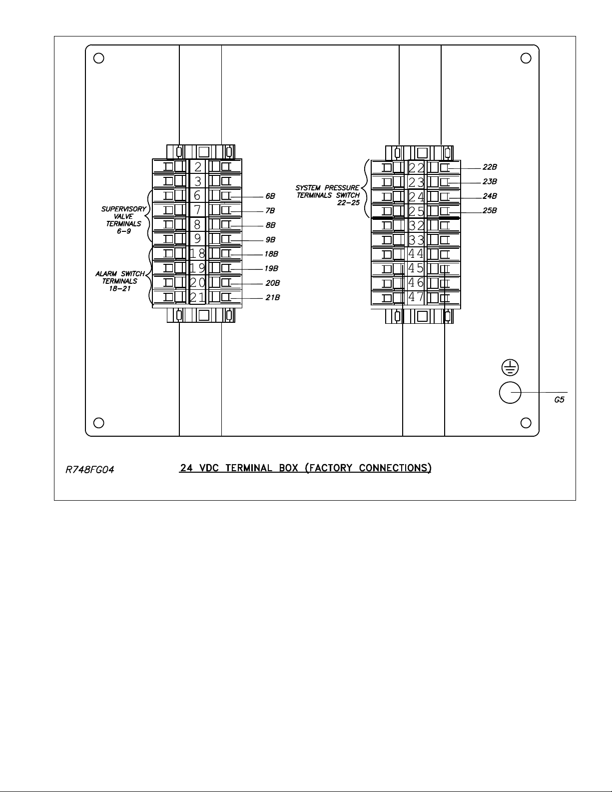
System Electrical Requirements
All 24 VDC electrical connections in the Reliable Model
DDX-LP PrePak are translated to a water tight terminal box
mounted on the inside of the enclosure. All field wiring con-
nections are made at this terminal box.
A separate power connection is provided for the optional
air compressor.
Note: The air compressor must be connected to a
grounded metallic, permanent wiring system, or an equip-
ment grounding terminal or lead on the product. Power sup-
ply wiring must conform to all required safety codes and be
installed by a qualified person. Check that the supply volt-
age agrees with that listed on compressor nameplate. Also
the wires running from the main electrical supply to the com-
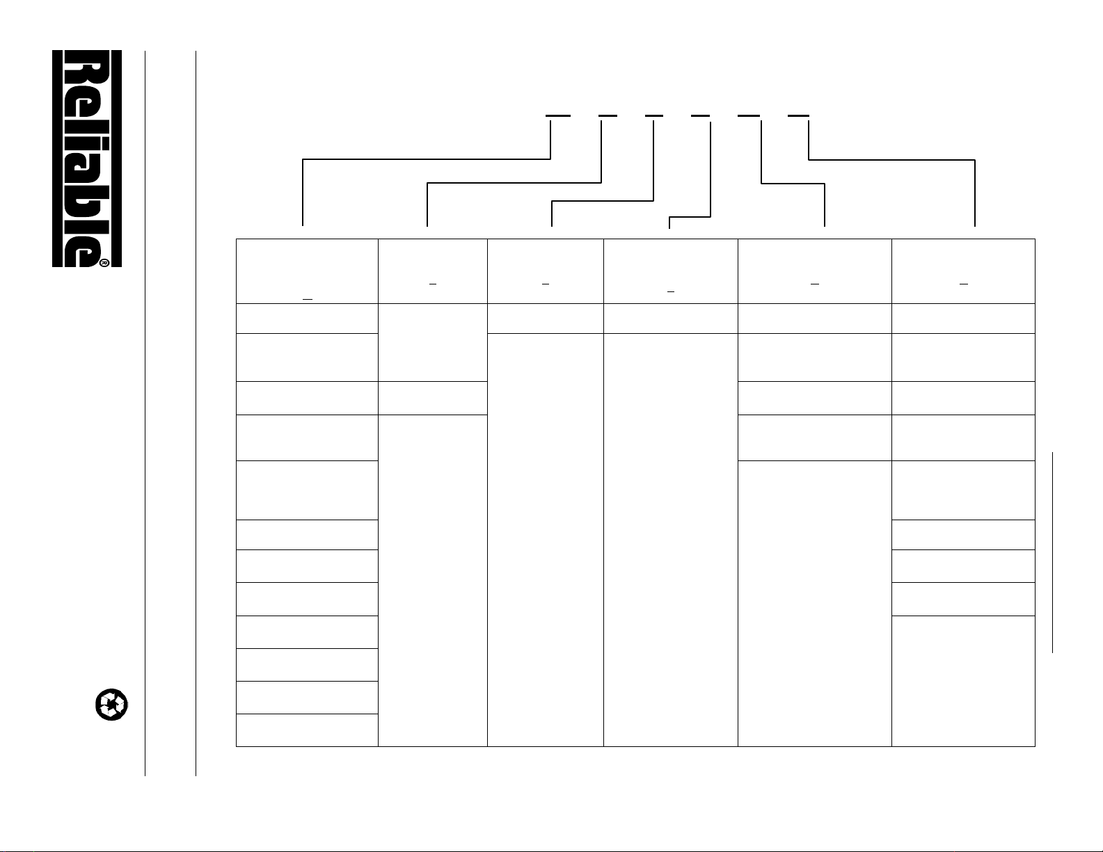
pressor must agree with the values specified in Table C. An
undersized wire is a potential fire hazard and will cause a
drop in line voltage resulting in loss of power causing the
compressor to overheat.
Table C
Amps Volts Length of cord in feet
120v 20 50 100 150 200 250 300 400 500
240v 60 100 200 300 400 500 600 800 1000
0-2 18 18 18 16 16 14 14 12 12
2-3 18 18 16 14 14 12 12 10 10
3-4 18 18 16 14 12 12 10 10 8
4-5 18 18 14 12 12 10 10 8 8
5-6 18 16 14 12 10 10 8 8 8
6-8 18 16 12 10 10 8 6 6 6
8-10 18 14 12 10 8 8 6 6 4
10-12 16 14 10 8 8 6 6 4 4
12-14 16 12 10 8 6 6 6 4 2
14-16 16 12 10 8 6 6 4 4 2
16-18 14 12 8 8 6 4 4 2 2
18-20 14 12 8 6 6 4 4 2 2
The Reliable Model DDX-LP PrePak is available with the
following factory installed electrical devices:
1. A system low air pressure switch, which is used to
monitor sprinkler piping.
2. An alarm pressure switch, which indicates actuation
of the system.
3. An optional low nitrogen pressure switch, which indi-
cates a depleted nitrogen supply.
4. An optional air compressor.
5. A supervised supply side butterfly water control valve.
6. A optional supervised system side butterfly water con-
trol valve.
The factory electrical connections of these devices are
illustrated in Fig. 3.
Maintenance
The Reliable DDX-LP PrePak and associated equipment
shall periodically be given a thorough inspection and test.
NFPA 25, Standard for Inspection, Testing and Maintenance
of Water Based Fire Protection Systems, provides minimum
maintenance requirements. Systems should be tested, op-
erated, cleaned and inspected at least annually, and parts
replaced as required. Periodically open the condensate
drain valve beneath the air tank to drain any condensate ac-
cumulation. Reliable Technical Bulletins 338 and 519 pro-
vide additional information for maintaining the Model DDX-
LP PrePak Deluge Valve.
System Setup (Refer to Figure 2)
1. Close the main valve controlling water supply to the
Model DDX-LP PrePak deluge valve. Also, close the
two ¼” valves supplying air or nitrogen to the system.
2. Close the pushrod chamber supply valve.
3. Open the main drain valve and drain the system.
4. Open all drain valves and vents at low points through-
out the system, closing them when flow of water has
stopped.
5. Open the Manual Emergency Release valve. Note: The
above steps accomplish the relieving of pressure in the
pushrod chamber of the deluge valve.
6. Push in the plunger of ball drip valve to force the ball
from its seat, and drain any water in the alarm line.
7. Push in and rotate the deluge valve’s external reset knob
counter-clockwise (when facing valve) until you hear a
distinct clicking noise, indicating that the clapper has
reset. Note: The reset knob can be rotated only after
pressure in the pushrod chamber is reduced to atmo-
spheric conditions (0 psig).
8. Inspect and replace any portion of the sprinkler system
subjected to fire conditions.
9. Verify that the following valves are in their respective po-
sitions prior to continuing:
Manual Emergency Release - open
Main Drain Valve - open
Alarm Line Valve - open
Alarm Test Valve - closed
Condensate Drain valve - closed
Air/Nitrogen Supply Valves - closed
10. Open pushrod chamber supply valve and allow water
to fill the pushrod chamber. Close the Manual Emer-
gency Release valve after any trapped air has had a
chance to escape from the deluge valve’s pushrod
chamber.
11. Upon seeing this solid flow of water coming out of the
Model LP Dry Pilot Actuator, open the Rapid-Air Fill
Valve thereby rapidly applying compressed air or ni-
trogen into the Model LP Dry Pilot Actuator and the
sprinkler system until the pressure conforms to Table
A levels, as indicated by the system air pressure
gauge. The Model LP Dry Pilot Actuator will eventually
close during this pressurizing process and water will
stop flowing through the drain tube. At this point, the
pressure gauge on the pushrod chamber pressure will
equalize to the available water supply pressure. Once
the actuator is set up correctly, close the Rapid-Air Fill
Valve and open the Regulated Air Shutoff Valve.
Note: For systems using nitrogen as the primary
source, the system may be set up using the nitrogen
source following the steps above. The air compres-
sor, if present, may then be placed into operation as
the backup pneumatic source.

6.
12. Open the alarm line valve.
13. If the Model B1 Accelerator Kit is installed, open valve
P. Prior to opening valve P, be sure that the Model B1
Accelerator has been successfully reset per Reliable
Technical Bulletin 323.
Note: The B1 Accelerator requires a minimum of 15
psi (1,0 bar) supervisory air or nitrogen pressure for
proper operation.
14. Slightly open the main valve controlling water supply
to the Model DDX-LP PrePak Deluge Valve. This will
begin to fill the deluge valve beneath the clapper with
water. Once any trapped air has been vented, close
the main drain valve. Observe if water leaks through
the ball drip valve into the 1” drain manifold through
the clear tubing. If no leakage occurs, the deluge
valve clapper is sealed. Fully open the main valve
controlling the water supply to the Model DDX-LP Pre-
Pak Deluge Valve and that it is properly monitored
15. Verify that the pushrod chamber supply valve is open.
16. Secure the handle of the Model B Manual Emergency
Station in the OFF position with a nylon tie (supplied
with the assembly).
Inspection And Testing Of The DDX-LP PrePak
Systems (Refer to Figure 2)
1. Water supply — Verify that the valve controlling water
supply to the deluge valve is opened fully and properly
monitored.
2. Pushrod Chamber supply — Verify that the valve sup-
plying water to the pushrod chamber is open.
3. Other trimming valves — Verify that the alarm line valve
is open as well as all of the pressure gauge valves. The
main drain valve, alarm test valve, and condensate
drain valve should be closed.
4. Ball drip valve — Push in on the plunger to be sure the
ball check is off its seat. If no water appears, the deluge
valve’s water seat is tight. Inspect the small bleed hole
located on the underside of the Model DDX-LP PrePak
Deluge Valve pushrod chamber for leakage.
5. System air pressure — Verify that system air pressure
is in conformance with the values posted in Table A for
the supply water pressure.
6. Releasing device — Check the outlet of the (Model LP
Dry Pilot Actuator and Model B Manual Emergency Sta-
tion) for leakage. Also verify that tubing drain lines from
releasing devices are not pinched or crushed which
could prevent proper releasing of the deluge valve.
7. Testing alarms — Open the alarm test valve permit-
ting water from the supply to flow to the alarm pressure
switch and to the mechanical sprinkler alarm (if pres-
ent). After testing, close this valve completely. Push
in on the plunger of ball drip until all of the water has
drained from the alarm line.
8. Operational test — Open the Model B Manual Emer-
gency Station or, alternatively, reduce air/nitrogen pres-
sure on the system. Note: An operational test will cause
the Deluge Valve to open and flow water into the sprin-
kler system.
9. Secure the Model B Manual Emergency Station in
the OFF position with a nylon tie (included with the as-
sembly) after the deluge valve is reset.
Testing the Model DDX-LP PrePak Deluge
Valve Without Flowing Water (Refer to Fig-
ure 2)
1. Close the valve controlling water supply to deluge valve
and open the main drain.
2. Verify that the pushrod chamber supply valve is open,
allowing water to enter the pushrod chamber.
3. Close the air/nitrogen supply to the sprinkler system.
4. Decrease pneumatic pressure in the system by opening
the condensate drain valve, until the Model LP Dry Pilot
Actuator operates. Doing so will result in a sudden drop
of water pressure in the deluge valve pushrod chamber.
5. Reset the system per the directions listed in “System
Setup” section of this bulletin.
Draining Excess/Condensate Water From System
1. Close the main valve controlling water supply to the Model
DDX-LP system.
2. Close the pushrod chamber supply valve, and open the
main drain valve.
3. Slightly open the condensate drain valve until all water
has drained, then close.
Note: Leaving the condensate drain open for an extended
period of time may allow excess air/nitrogen to bleed off and
result in accidental release of the Model LP Dry Pilot Actua-
tor and/or the Model DDX-LP valve.
4. Close the main drain valve. Allow the system air/nitrogen
pressure to return to its previous level. Open the pushrod
chamber supply valve first, and then open the main valve
controlling water supply to the system.

Fig. 2
7.
Model DDX-LP Low Pressure Dry Pipe System
Valve Legend
(Note: Some items omitted for clarity)

8.
Fig. 3

9.
Fig. 4

Reliable Automatic Sprinkler Co., Inc.
(800) 431-1588 Sales Offices
(800) 848-6051 Sales Fax
(914) 829-2042 Corporate Offices
www.reliablesprinkler.com Internet Address
Manufactured by
Recycled
Paper
Revision lines indicate updated or new data.
EG. Printed in U.S.A. 07/19 P/N 9999970425
The equipment presented in this bulletin is to be installed in accordance with the latest published Standards of the National Fire Protection Association, Factory
Mutual Research Corporation, or other similar organizations and also with the provisions of governmental codes or ordinances whenever applicable.
Products manufactured and distributed by Reliable have been protecting life and property for almost 100 years.
Note:
(1) No Solenoid Valve or Control Panel are utilized with this trim. If selected, the 6th and 7th digits in the P/N are required to be “0” (None).
(2) Not Used
(3) Air Compressor sizing may differ if specified sprinkler system has an uncommon volume capacity.
DDX-LP PrePak Valve
Size/System
Side Control Valve
U
Trim Type
3
Solenoid Valve
0
Releasing/Control
Panel
0
Air Compressor(3)
Y
System Air Devices
Z
2 = 2” 0 = None 0 = None 0 = None 0 = None
0 = 2-1/2” 1 = 1/2 HP 115 VAC
(systems up to 3” in size) 1 = Nitrogen Supply Kit
3 = 3” 3 = PrePak(1) 2 = 1 HP 115 VAC
(for 4” systems)
2 = Nitrogen Supply Kit &
Model B Accelerator
4 = 4” 3 = 1-1/2 HP 115 VAC
(for 6” & 8” systems)
3 = NS-ASAM (Nitrogen
Supply w/ Auto Switchover
and Monitoring)
6 = 6”
4 = NS-ASAM (Nitrogen
Supply w/ Auto Switchover
and Monitoring) & Model
B Accelerator
8 = 8” 5= Model B Accelerator
A = 2” w/ System Side
Control Valve 6 = Desiccant Kit
B = 2-1/2” w/ System Side
Control Valve
7 = Desiccant Kit &
Model B Accelerator
C = 3” w/ System Side
Control Valve
D = 4” w/ System Side
Control Valve
E = 6” w/ System Side
Control Valve
F =8” w/ System Side
Control Valve
655 U 3 0 0 Y Z 0
Ordering Information: PrePak Part Number Configuration
Other manuals for DDX-LP PrePak
1
Table of contents
Other Reliable Water System manuals
Popular Water System manuals by other brands

AquaPur
AquaPur VALROM Espresso 600GPD manual

Everpure
Everpure Single Head EV9259-24 Specification sheet

ModvlvS
ModvlvS Kascata manual

Zip
Zip HydroTap G4 BCS160/175 Installation and operating instructions

Beko
Beko QWIK-PURE 10 Installation and operation manual

Vantage Hearth
Vantage Hearth ACF-18 Installation and operation manual

Kelvinator
Kelvinator KGC20BNA user manual

Elkay
Elkay ECP8 1F Series Installation, care & use manual

Water Control
Water Control WHRO-700 installation manual

WaterLogic
WaterLogic 12-WL200CT manual

HeadHunter
HeadHunter X-CALIBER XR-124 Installation and operation manual

Xylem
Xylem CentriPro Aquavar SOLO 2 Frequently asked questions