Reliable DDX PrePaK Maintenance manual

Reliable Automatic Sprinkler Co., Inc., 103 Fairview Park Drive, Elmsford, New York 10523
Model DDX PrePaK,
Type D Preaction System
2” (50mm), 2-1/2” (65mm), 3”
(80mm), 4”(100mm),
6” (150mm) & 8” (200mm)
Bulletin 733 February 2019
Instructions for
Installation, Operation,
Care and Maintenance
10 PSI (0.7 bar) Pneumatic Supervising Pressure
Single Interlock - Electric Release
Double Interlock - Electric/Electric Release
General Description
The Reliable Model DDX PrePaK is a completely self-con-
tained, supervised preaction system that can be readily installed
within a floor space of 4.7 ft2(0.43 m2) for the 2”, 2-1/2”, and 3”
systems, and 6.5ft2(0.60m2)for the 4”, 6”, and 8” systems (not
including door swing). Installation of the PrePaK (not including
exterior devices, i.e., detectors and alarm bells) requires three
piping connections: the water supply, the sprinkler system, and
the drain. Reference locations of these piping connections are
shown in Fig.1. Two electrical supply connections are required.
Note: The Model DDX PrePak is available with an optional 115V
VAC (60Hz) air compressor and an optional Potter Model PFC-
4410-RC Releasing/Control panel wired for a 120 VAC (50Hz) or
220 VAC (50/60Hz) power supply.
Full assembly drawings for the units are available on the Reli-
able Automatic Sprinkler Company website (www.reliablesprin-
kler.com).
The Reliable Model DDX PrePaK utilizes an optional Potter
Model PFC-4410-RC Releasing Control Panel. This fully pro-
grammable, microprocessor-based releasing panel is Under-
writers Laboratories, Inc. Listed and is in compliance with NFPA
13 and NFPA 72. The PFC-4410-RC is totally zone and output
programmable such that the Reliable Model DDX PrePaK can
be utilized in many different preaction applications without hav-
ing to rewire any of the factory installed devices. Once the previ-
ously described connections are completed, the 24 VDC detec-
tors, output devices, and relay contacts may be connected to
achieve the desired system implementation.
The Model DDX Type D PrePaK can be used in both single
and double interlock applications. Reliable Single and Double
Interlock Preaction Systems are designed for water sensitive ar-
eas that require protection from inadvertent water flow into the
sprinkler system piping.
The major benefits of a single/double interlock preaction Sys-
tem, when compared with a wet pipe system, are as follows:
A. A fire alarm sounds prior to the flow of water from a sprin-
kler, which may enable extinguishing the fire by handheld
means before the operation of any sprinkler occurs.
B. An annunciator signals whenever the integrity of piping or
sprinklers is accidentally or intentionally disturbed; howev-
er, no water flow occurs unless the detection system has
been activated .

2.
C. Detection and notification of a fire condition are provided
by fire detectors, without the delay associated with water
delivery time in the event of a fire. Note that with a wet pipe
system, the fire alarm is delayed until after water has begun
flowing from an operated sprinkler.
In single interlock applications, one or more detectors sense
the presence of fire, thereby causing the electrical releasing
control panel to activate notification appliances and energize
the solenoid releasing valve to the open position. The use of
cross-zoned detectors will require operation of two detectors on
separate zones before the solenoid valve can open (Note: Ver-
ify that the detection method, including the use of cross-zoned
detection, are permitted by all applicable codes and standards,
as well as the requirements of all authorities having jurisdiction.
Cross-zoned detection may not be permitted in New York City
or by Factory Mutual.) The solenoid valve, when closed, pre-
serves supply water pressure in the Model DDX valve’s push-
rod chamber. Actuating the solenoid valve releases that water
pressure which allows the Model DDX valve to open.
To discharge water from sprinklers on a single interlock sys-
tem with cross-zoned detection, two separate electrical detec-
tion zone must activate and a sprinkler must open. During the
early stages of a fire, smoke or heat activates the first detector,
which causes the control panel to produce a local alarm and an
alarm at the fire alarm panel. Electrical relays inside the releasing
control panel can be used to shut down air moving equipment
or activate security doors and other electrical devices when the
panel goes into this first condition. Subsequent activation of a
second, nearby or adjacent detector, on a separate detection
zone, will cause the panel to energize the solenoid valve open
and release water into the sprinkler piping. Water flowing into
the sprinkler piping will simultaneously produce water pressure
that cause the transfer of contacts in the alarm pressure switch
mounted in the riser assembly, thereby activating a water flow
alarm device. The flow of water into the sprinkler piping effec-
tively converts the dry system into a wet-pipe sprinkler system.
In the event that the fire subsequently produces sufficient heat to
operate a sprinkler, water will flow from that sprinkler.
To flow water into a double interlock preaction system, two
events must take place: a fire detection device must operate,
and a pressure switch must be operated by the loss of system
pressure (sprinkler operation). These two signals, an electric
signal from the detection system and an electrical signal from
the pressure (pneumatic) sensor, must coexist at the releasing
control panel, which only then will energize the solenoid releas-
ing valve causing water flow into the sprinkler system and out of
the open sprinkler(s).
In the event that the system piping is ruptured or a sprinkler
is accidentally opened, the system pressure switch will oper-
ate and an alarm will sound. The Model DDX Type D however,
will not release water since the detection system has not been
activated.
When using the Reliable Model DDX PrePaK in either single
or double interlock applications, the sprinkler system is pres-
surized (supervised) with air or nitrogen and is monitored by a
system pressure switch.
A Model B Hydraulic Manual Emergency Releasing station is
standard equipment in the Model DDX PrePaK. It consists of an
aluminum nameplate mechanically attached to a ball valve. The
valve handle in its OFF position is guarded against accidental
turning to the ON position (and system discharge) by a nylon
cable tie provided with the PrePaK assembly. The cable tie is
designed to allow, in case of an emergency, forceful turning of
the valve handle to the ON position.
Approvals
1. Underwriters Laboratories, Inc. Listed and Certified for
Canada* (cULus) as an assembled unit in the “Special
System Water Control Valves Assembled Units” category,
(VKYL).
2. Factory Mutual (FM) Approved, as PrePak Single Interlock
and Double Interlock Preaction Systems.
* Electrical devices and control panel must be specified
to meet Canadian requirements. This option is avail-
able.
3. Approved for use in New York City based on UL Listing.
Note: Although PrePak units are UL Listed, custom built units
are sometimes supplied upon request. The components within
these special units maintain their individual Listings/Approvals,
whereas the assembled units do not.
PrePak units are also available without the Potter PFC-4410-
RC Releasing/ Control Panel and Air Compressor. These units
will still retain their Listings/Approvals, however the installing
contractor should make sure that any remote controlled Releas-
ing/Control Panels used with these units are Listed/Approved
and programmed to handle the required sequence of opera-
tion necessary to operate the automatic sprinkler system. Any
unauthorized modification or addition made on-site to a factory-
built Listed/Approved unit will void the Listing/Approval. Such
modifications or additions may void the unit’s warranty as well.
Consult Reliable’s Technical Services Department before pro-
ceeding with any such modifications or additions.
Technical Data
1. The Reliable Model DDX PrePaKs are rated for a minimum
supply pressure of 20 psi (1.4 bar) and a maximum supply
pressure of 250 psi (17.2 bar).
2. Friction loss, expressed in equivalent length of Schedule 40
pipe and based on Hazen-Williams Formula with C=120
and a flowing velocity of 15 ft/s (4.6 m/s), is:
System Size Equivalent Length
2” (50mm) 4.4’ (1.3m)
2-1/2” (65mm) 6.0’ (1.8m)
3” (80mm) 12.6’ (3.8m)
4” (100 mm) 32.8 ft (17.7 m)
6” (150 mm) 54.7 ft (21.8 m)
8” (200mm) 79.3ft (24.2m)
These values account for the Model DDX valve, supply
manifold tee, butterfly control valve, and the short section of
pipe located directly above Model DDX valve.
3. Shipping Weight:
System Size Weight
2” (50mm)
565 lbs (256 kg)2-1/2” (65mm)
3” (80mm)
4” (100 mm) 690 lbs (313 kg)
6” (150 mm) 850 lbs (386 kg)
8" (200mm) 940lbs (426kg)
4. Please reference Figure 1 for dimensions.

Fig. 1
3.

4.
The following is a list of Technical Data Bulletins which de-
scribe the valves and devices which are used in the system:
Device Reliable Bulletin #
(unless otherwise noted)
Model DDX Deluge Valve Reliable Bulletin 519
Type D Double Interlock Preaction Trim Reliable Bulletin 750
Low Air Pressure Switch Potter 5400928
Alarm Pressure switch Potter 5400928
Nitrogen Pressure Switch Potter 5400930
Mechanical Sprinkler Alarm Reliable Bulletins 612/613
Releasing Control Panel Potter Manual #5403550
Fire Alarm Devices Reliable Bulletin 700
Desiccant Dryer Wilkerson Catalog 9EM-TK-190-4
The following table provides a quick reference to various pro-
grams (found in this bulletin and the Potter Manual #5403550)
that may be utilized with a Model DDX PrePaK:
Desired Application Program
Single Interlock,
Single Zone
Potter Program #6
(Factory Setting)
Potter Program #7
Single Interlock,
New York City Custom NYC Program
Double Interlock,
Single Zone Potter Program #9
Double Interlock,
Cross Zoned Potter Program #10
*Note: Factory Program setting.
Installation Requirements
The automatic sprinklers, releasing devices, fire detection
devices, manual pull stations, and signaling devices which are
utilized with the Reliable Model DDX Type D PrePaK must be UL
and/or ULC Listed or FM Approved, as applicable.
The steel enclosure and all the interconnecting piping must
be located indoors in a readily visible and accessible location
and in an area that can be maintained at a minimum tempera-
ture of 40°F (4°C). Note: Heat tracing is not permitted. The so-
lenoid valve is operated and supervised by the Potter Model
PFC-4410-RC Releasing Control Panel. Details on the electrical
connections of this system to the Potter Panel can be found in
the Potter Manual #5403550, Installation, Operation and Instruc-
tion of PFC-4410-RC Releasing Control Panel (this manual is
included with other pertinent manuals and shipped inside the
enclosure). This panel is fully zone and output programmable
and may be adapted to several applications.
System Supervising Pressure Requirements
In accordance with NFPA 13, when using the Reliable Model
DDX Type D PrePaK in double interlock applications, a mini-
mum of 7 psi (0.5 bar) pneumatic pressure is required to su-
pervise the sprinkler system. When initially filling the system with
air, the enclosure’s door should remain open in order to provide
maximum intake air flow to the air compressor. The air com-
pressor is connected to an ASME rated storage tank. This tank
functions as a reservoir, providing make-up air to compensate
for small, intermittent leaks in the sprinkler system. It should be
noted that significant leaks may overburden this storage tank,
thereby causing the air compressor to continuously cycle on
and off.
The Pressure Maintenance Device supplied with the system
is factory set to maintain system pneumatic pressure at approxi-
mately 10 psi (0.7 bar). Readjusting system pressure to approxi-
mately 10 psi (0.7 bar), if necessary, is accomplished by first
loosening the locknut on the air pressure regulator and turning
the adjustment screw. The system air pressure gauge that is
attached to the vertical pipe/manifold (mounted directly above
the Model DDX Deluge Valve) may be used to verify the correct
level of pneumatic pressure.
The system air pressure switch is factory set to operate be-
tween 8 psi and 4 psi (0.6 bar and 0.3 bar) with decreasing
pressure.
System Electrical Requirements
All releasing, alarm, and detection devices in the Reliable
Model DDX Type D PrePaK are supervised by a Potter Model
PFC-4410-RC Releasing Control Panel. All of the terminals are
translated to a water-tight terminal box mounted on the interior of
the enclosure. All field wiring is connected to this terminal box.
Note: The EOL (End of Line) resistors have also been relocated.
The Reliable Model DDX PrePaK is delivered with six factory-
installed electrical devices. They consist of the following:
1. A system air pressure switch, which is used to monitor
sprinkler piping.
2. An alarm pressure switch, which indicates an actuation of
the deluge valve.
3. A normally-closed, releasing solenoid valve, which is used
to actuate the deluge valve.
4. A 1/2 HP (2”, 2-1/2”, & 3” valve), 1 HP (4” valve), or 1-1/2 HP
(6” & 8” valve) air compressor with tank.
5. A supervised butterfly (main control) valve (Note: A system
side butterfly valve is available as an option).
6. A release control disable switch (RCDS) which is
used to disable the solenoid valve for test purposes.
The factory electrical connections of these devices, along
with information on the connection of detection devices
(initiating zones 1 and 2), signaling devices, and supervi-
sory outputs to the Potter PFC4420-RC Releasing Control
Panel are included in this bulletin. The power supply,
standby emergency power supply, battery charger and
rectifier circuitry are all contained within the PFC4410
panel. Batteries that provide 90 hours of standby power
are provided with the panel. For additional information
and detailed wiring diagrams, please refer to Potter Man-
ual #5403550 (Installation, Operation, and Instruction of
PFC4410-RC Releasing Control Panel).
Note: In order for the solenoid valve to maintain a warranty
it must remain sealed as it came from the factory. If there are
concerns about the valve’s internal components, immediate re-
placement is recommended.

5.
System Operation (Single Interlock)
To fully activate and discharge water from the Reliable Mod-
el DDX Type D PrePaK in a single interlock application, a fire
detection device (smoke, heat, etc.; or two devices with cross-
zoned detection) must activate. Subsequently, a fire sprinkler
must open.
When the single interlock preaction system is set for service,
the supply pressure acts both on the underside of the deluge
valve’s clapper and on the valve’s push rod by means of the
pressurized push rod chamber. The pressure force acting on
the push rod, when utilized with the mechanical advantage of
the deluge valve’s lever, is more than sufficient to hold the clap-
per in the closed position against the water supply pressure.
Energizing the releasing solenoid the pushrod chamber sup-
ply valve allows the deluge valve push-rod chamber to be vent-
ed to drain. Since the pressure cannot be replenished through
the inlet restriction as rapidly as it is vented though the outlet,
the push-rod chamber pressure falls rapidly. When the push-rod
chamber pressure drops below one-third of the supply pres-
sure, the opening force acting beneath the clapper becomes
greater than the push-rod force acting on the lever. This causes
the clapper to open. Refer to Reliable Bulletin 519 for further de-
tails.
Once the clapper has opened, the lever acts as a latch, pre-
venting the clapper from returning to the closed position. Water
from the supply flows through the deluge valve into the system
piping. Water also flows through the deluge the pushrod cham-
ber supply valve alarm outlet to activate any water flow alarm
devices. Note that the solenoid valve will be maintained open by
the Potter Model PFC-4410-RC Releasing Control Panel’s latch-
ing feature until it is reset for operation.
After system shutdown and draining, the Model DDX Deluge
Valve is easily reset without special tools using the external re-
set feature. Restore detection devices by resetting or replacing
any operated device. Once detection devices are restored, (the
Potter Model PFC-4410-RC Releasing Control Panel reset), and
supply pressure is re-supplied to the push-rod chamber, the
deluge valve is reset.
System Operation (Double Interlock)
To fully activate and discharge water from the Reliable Model
DDX Type D PrePaK in a double interlock application, two inde-
pendent events must coexist. An electrical fire detection device
(smoke, heat, etc.) and the system air pressure switch must be
activated. This pressure switch is activated by a reduction of the
system pneumatic pressure as a result of sprinkler operation.
Both of these events will cause the control panel to energize the
solenoid valve, thereby releasing water through the deluge the
pushrod chamber supply valve and into the sprinkler system.
The initiation of either one of these events will only cause an
alarm to annunciate, and will not fill the sprinkler system.
When the double interlock preaction system is set for service,
the supply pressure acts both on the underside of the deluge
valve’s clapper and on the valve’s push rod by means of the
pressurized push rod chamber. The pressure force acting on
the push rod, when utilized with the mechanical advantage of
the deluge valve’s lever, is more than sufficient to hold the clap-
per in the closed position against the water supply pressure.
Energizing the releasing solenoid the pushrod chamber sup-
ply valve allows the deluge valve push-rod chamber to be vent-
ed to drain. Since the pressure cannot be replenished through
the inlet restriction as rapidly as it is vented though the outlet,
the push-rod chamber pressure falls rapidly. When the push-rod
chamber pressure drops below one-third of the supply pres-
sure, the opening force acting beneath the clapper becomes
greater than the push-rod force acting on the lever. This causes
the clapper to open. Refer to Reliable Bulletin 519 for further de-
tails.
Once the clapper has opened, the lever acts as a latch, pre-
venting the clapper from returning to the closed position. Water
from the supply flows through the deluge valve into the system
piping. Water also flows through the deluge the pushrod cham-
ber supply valve alarm outlet to activate any water flow alarm
devices. Note that the solenoid valve will be maintained open by
the Potter Model PFC-4410-RC Releasing Control Panel’s latch-
ing feature until it is reset for operation.
After system shutdown and draining, the Model DDX Deluge
Valve is easily reset without special tools using the external re-
set feature. Restore detection devices by resetting or replacing
any operated device. Once detection devices are restored, (the
Potter Model PFC-4410-RC Releasing Control Panel reset), and
supply pressure is re-supplied to the push-rod chamber, the
deluge valve is reset.
Resetting Single And Double Interlock Systems
1. Close the main valve controlling water supply to the deluge
the pushrod chamber supply valve and close the ¼” air
shutoff valve.
2. Close the pushrod chamber supply valve.
3. Open the main drain the pushrod chamber supply valve
and drain system.
4. Open all drain valves and vents at low points throughout
the system, closing them when flow of water has stopped.
Open the Manual Emergency Release Valve. Note: The
above steps accomplish the relieving of pressure in the
pushrod chamber of the deluge valve.
5. Push in the plunger of ball drip valve to force the ball from its
seat, and drain any water in the alarm line.
6. With the Model B Manual Emergency Station open, push
in and rotate the deluge the alarm test valve external re-
set knob counterclockwise (when facing valve) until you
hear a distinct clicking noise, indicating that the clapper
has closed. Note: The reset knob can be rotated only after
pressure in the pushrod chamber is reduced to atmospher-
ic conditions (0 psig).
7. Inspect and replace any portion of the sprinkler system
subjected to fire conditions.
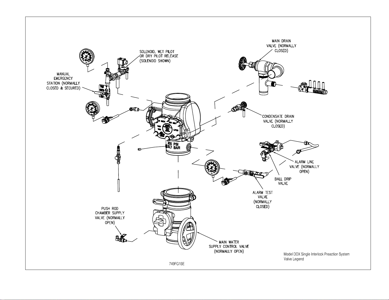
8. Verify that the following valves are in their respective posi-
tions:
Manual Emergency Release - open
Main Drain Valve - open
Alarm Line Valve - open
Alarm Test Valve - closed
Condensate Drain valve - closed
Air Supply Valves - closed
9. Open the pushrod chamber supply the pushrod chamber
supply valve and allow water to fill the deluge valve push-
rod chamber. Close the Manual Emergency Release valve.

6.
10. Bleed any air from the actuation piping by energizing the so-
lenoid valve. This is done by operating the electric manual
release station. While water is flowing through the solenoid
valve, cause it to close by pressing the system reset button
on the Potter PFC-4410-RC Releasing Control Panel. Note:
All detection devices and the manual pull station must be
reset before the releasing/control panel can be reset.
11. Open the air supply valve to restore air pressure in the sprin-
kler system. The rapid air-fill shutoff valve may be opened
to expedite filling of the sprinkler system.
12. Open slightly the main valve controlling water supply to
the Model DDX Deluge Valve, closing the main drain valve
when water flows. Observe if water leaks through the ball
drip valve into the drain manifold. If no leak occurs, the del-
uge valve clapper is sealed. Open slowly, and verify that
the main valve controlling water supply is fully opened and
properly monitored.
13. Verify that the pushrod chamber supply valve is fully open.
14. Secure the handle of the Model B Manual Emergency Sta-
tion in the OFF position with a nylon tie (supplied with the
assembly).
15. Press the system reset button on the Potter PFC-4410-RC
Panel to place the system in the ready condition. Note: All
detection devices must be reset before the panel can be
reset.
Maintenance
The Reliable Model DDX PrePaK and associated equipment
shall periodically be given a thorough inspection and test. NFPA
25, Standard for the Inspection, Testing and Maintenance of
Water Based Fire Protection Systems, provides minimum main-
tenance requirements. Systems should be tested, operated,
cleaned and inspected at least annually, and parts replaced as
required. Periodically open the air/condensate drain valve be-
neath the air tank to drain any condensate accumulation. Bul-
letin 519 provides information for maintaining the Model DDX
Deluge Valve. Potter Manual #5403550 provides information for
maintaining the PFC-4410-RC Releasing Control Panel.
Inspection And Testing Of Single And Double
Interlock Systems
1. Water supply — Verify that the valve controlling wa-
ter supply to the deluge valve is opened fully and
properly monitored.
2. Alarm line — Verify that the alarm line valve is
opened and remains in this position.
3. Other trimming valves — Verify that the pushrod
chamber supply valve is open as well as all of the
pressure gauge valves.
4. Ball drip valve — Push in on the plunger to be sure
the ball check is off its seat. If no water appears, the
deluge valve water seat is tight. Inspect the bleed
hole on the underside of the pushrod chamber for
leakage.
5. System pneumatic pressure — Verify that system
air pressure is between 7 and 10 psi (0.5 bar 0.7
bar). Check the Pressure Maintenance Device for
leakage and proper pressure.
6. Releasing device — Check the outlet of the re-
leasing device (i.e., solenoid valve or the Model B
Manual Emergency Station) for leakage. Also verify
that tubing drain lines from releasing devices are not
pinched or crushed which could prevent proper re-
leasing of the deluge valve.
7. Testing alarms — Open the alarm test valve permit-
ting water from the supply to flow to the alarm pres-
sure switch and to the mechanical sprinkler alarm (if
present). After testing, close this valve completely.
Push in on the plunger of ball drip until all of the wa-
ter has drained from the alarm line.
8. Operational test — Open the Model B Manual
Emergency Station only, OR operate the solenoid
valve by electrical actuation. This can be done by
operating a detector or an electric manual emergen-
cy station. Double interlock systems also require
that the system air pressure be discharged, through
the inspectors test station or other venting means,
below 4 psi (0.3 bar) before total system operation
will occur. Note: An operational test will cause the
Deluge Valve to open and flow water into the sprin-
kler system.
9. Secure the Model B Manual Emergency Station in
the OFF position with a nylon tie (included with the
assembly) after the deluge valve is reset.
Testing The Model DDX PrePaK Without
Causing Water Flow
1. Close the main valve controlling water supply to the deluge
valve and open the main drain valve.
2. Verify that the pushrod chamber supply valve is open, al-
lowing water to enter the push-rod chamber.
3. Operate the detection system. For double interlock appli-
cations, also disable the air supply and open the conden-
sate drain valve to discharge the system air pressure.
4. Step #3 should result in a sudden drop of water pressure
in the deluge valve push-rod chamber via an energized
solenoid valve.
5. Reset the detection system - Reverse the detection system
operations performed in Step #3 above. Note: All detec-
tion devices must be reset before the Potter PFC-4410-RC
Releasing Control Panel can be reset.
6. Proceed according to the directions listed in the “Reset-
ting Single And Double Interlock Systems” section of this
bulletin.

Draining Excess/Condensate Water From
The System
1. Close the main valve controlling water supply to the deluge
valve and the pushrod chamber supply valve. Open the
main drain valve.
2. Slightly open the condensate drain valve until all water (if
any) drains completely. Note: Leaving the condensate
drain valve open for an extended period of time may allow
excess air to bleed off resulting in an undesirable low pres-
sure supervisory signal.
3. Close the main drain valve. Allow the system air pressure
to return to its previous level. Open the pushrod chamber
supply valve first, and then open the main valve controlling
the water supply to the deluge valve.
SOLENOID VALVE INSPECTIONS, TESTS
AND MAINTENANCE
WARNING: THE OWNER IS RESPONSIBLE FOR MAIN-
TAINING THE FIRE PROTECTION SYSTEM IN PROP-
ER OPERATING CONDITION. ANY SYSTEM MAIN-
TENANCE OR TESTING THAT INVOLVES PLACING A
CONTROL VALVE OR DETECTION SYSTEM OUT OF
SERVICE MAY ELIMINATE THE FIRE PROTECTION
OF THAT SYSTEM. PRIOR TO PROCEEDING, NOTIFY
ALL AUTHORITIES HAVING JURISDICTION. CONSID-
ERATION SHOULD BE GIVEN TO EMPLOYMENT OF
A FIRE PATROL IN THE AFFECTED AREA.
WARNING: PRIOR TO OPERATING THE SOLENOID
VALVE, BE SURE TO CLOSE THE SYSTEM CONTROL
VALVE TO AVOID UNINTENTIONAL OPERATION OF
THE DELUGE VALVE
1. Inspections: It is imperative that the system be inspected
and tested in accordance with NFPA 25 on a regular basis.
The frequency of the inspections may vary due to contami-
nated water supplies, corrosive water supplies, or corrosive
atmospheres. In addition, the alarm devices, detection sys-
tems, or other connected trim may require a more frequent
schedule. Refer to the system description and applicable
codes for minimum requirements.
2. The valve must be inspected at least monthly for cracks,
corrosion, leakage, etc., cleaned and replaced as neces-
sary.
3. If leakage is suspected through the solenoid valve, it should
be replaced.
7.

Fig. 2
8.
Note: Trim valve location is common to wet pilot
line, dry pilot line, and electric release systems.

Fig. 3
9.

10.
Fig. 4

11.
Fig. 5

Fig. 6
12.

13.
Fig. 7

Fig. 8 — Wiring Diagram
14.

15.
Fig. 9 — Wiring Diagram

POTTER PROGRAM #6
OUTPUTS
ZONES
Supervisory 2 (1)
#1
Conventional (2)
#2
Conventional(2)
#3
Waterflow
#4
Low Air Supervisory
#1 ALARM X
#2 WATERFLOW X
#3 SUPERVISORY X X
#4 RELEASE X
Single Interlock, Single Detection Zone
Potter Program #6
1. Apply power to panel.
2. Slide the program switch down.
3. Press the FUNCTION button until the display reads “PASS-
WORD=000.”
4. To enter a password, press the SELECT button until the
proper number is displayed above the “^” symbol; then
press the SET button to move to the next digit. After enter-
ing the third number the display will change. (All panels are
shipped with a “000” password.)
16.
5. Press the FUNCTION button until the display reads “PRO-
GRAM ##.” (the second “#” character refers to the current
program number between “0” and “24”).
6. Press the SELECT button until the display reads “PRO-
GRAM #6.”
7. Press the SET button
8. The panel is completely programmed except for the cus-
tom banner and zone messages. Slide the program switch
back up.
INPUTS: 1 conventional zone, 1 manual release zone, 1 waterflow zone, 1 low air zone, 1 supervisory zone.
OUTPUTS: 1 general alarm bell, 1 waterflow bell, 1 supervisory bell, 1 solenoid release circuit.
OPERATION: Activation of either conventional zone (or operation of the manual pull station within the PrePak cabi-
net) will operate the solenoid release circuit and the general alarm bell. Activation of the waterflow
zone will operate the waterflow bell. Activation of either the low air zone or the supervisory zone will
operate the supervisory bell. When either Zone #1 or #2 is in alarm, Output #1 (general alarm) and
Output #4 (solenoid release) will operate. When Zone #3 is in alarm, Output #2 (waterflow bell) will
operate. When either Zone #4 or the supervisory zone is activated, Output #3 (supervisory bell) will
operate.
Note:
(1) The Butterfly valve in the PrePaK assembly is connected to Supervisory 2 input of the Potter PFC-4410RC Releas-
ing/Control panel
(2) The emergency manual release within the PrePak cabinet is wired into the conventional detection zones 1 and 2,
and is designed to release the solenoid for setup and testing purposes.
For additional Information, please refer to the “Installation, Operation, and Instruction Manual” for the Potter
PFC4410-RC Releasing Control Panel (provided with the unit).

Single Interlock, Cross Zoned Detection
Potter Program #7
1. Apply power to panel.
2. Slide the program switch down.
3. Press the FUNCTION button until the display reads “PASS-
WORD = 000.”
4. To enter a password, press the SELECT button until the
proper number is displayed above the “^” symbol; then
press the SET button to move to the next digit. After enter-
ing the third number the display will change. (All panels are
shipped with a “000” password).
5. Press the FUNCTION button until the display reads “PRO-
GRAM ##.” (the second “#” character refers to the current
program number between “0” and “24”).
6. Press the SELECT button until the display reads “PRO-
GRAM #7.”
7. Press the SET button.
8. The panel is completely programmed except for the cus-
tom banner and zone messages. Slide the program switch
back up.
INPUTS: 2 conventional zones (cross-zoned), 1 waterflow zone, 1 low air zone, 1 supervisory zone.
OUTPUTS: 1 general alarm bell, 1 waterflow bell, 1 supervisory bell, 1 solenoid release circuit.
OPERATION: Activation of both conventional zones at the same time (or operation of the manual pull station within
the PrePak cabinet) will operate the solenoid release circuit and the general alarm bell. Activation of
either conventional zone will operate the general alarm bell. Activation of the waterflow zone will op-
erate the waterflow bell. Activation of either the low air zone or the supervisory zone will operate the
supervisory bell. When either Zone #1 or #2 is in alarm, Output #1 (general alarm) will operate. When
Zones #1 and #2 are in alarm at the same time, Output #4 (solenoid release) and Output #1(general
alarm) will operate. When Zone #3 is in alarm, Output #2 (waterflow bell) will operate. When either
Zone #4 or the supervisory zone is activated, Output #3 (supervisory bell) will operate.
Note:
(1) The Butterfly valve in the PrePaK assembly is connected to Supervisory 2 input of the Potter PFC-4410RC Releas-
ing/Control panel
(2) The emergency manual release within the PrePak cabinet is wired into the conventional detection zones 1 and 2,
and is designed to release the solenoid for setup and testing purposes.
For additional Information, please refer to the “Installation, Operation, and Instruction Manual” for the Potter
PFC4410-RC Releasing Control Panel (provided with the unit).
POTTER PROGRAM #7
OUTPUTS
ZONES
Supervisory 2 (1)
#1
Conventional (2)
#2
Conventional(2)
#3
Waterflow
#4
Low Air Supervisory
#1 ALARM X X
#2 WATERFLOW X
#3 SUPERVISORY X X
#4 RELEASE XX XX
17.

Double Interlock Preaction, Single Zone Detection
Potter Program #9
1. Apply power to the panel.
2. Slide program switch down.
3. Press the FUNCTION button until display reads “PASS-
WORD=000.”
4. To enter a password, press the SELECT button until the
proper number is displayed above the “^” symbol; then
press the SET button to move to the next digit. After enter-
ing the third number, the display will change. (All panels are
shipped with a “000” password).
5. Press the FUNCTION button until the display reads “PRO-
GRAM ##.” (the second “#” character refers to the current
program number between “0” and “24”).
6. Press the SELECT button until the display reads “PRO-
GRAM #9.”
7. Press the SET button.
8. The panel is completely programmed except for the cus-
tom banner and zone messages. Slide the program switch
back up.
INPUTS: 1 supervisory zone, 1 conventional detection zone, 1 low air supervisory zone, 1 waterflow zone, 1 low
air alarm zone.
OUTPUTS: 1 general alarm, 1 supervisory, 1 waterflow, 1 solenoid release circuit.
OPERATION: Activation of the conventional detection zone and the low air alarm zone at the same time (or operation
of the manual pull station within the PrePak cabinet) will operate the solenoid release circuit and the
general alarm bell.
Activation of the conventional zone only will operate the general alarm output.
Activation of the low air supervisory zone will operate the supervisory bell output.
Activation of the waterflow zone will operate the waterflow bell output.
Activation of the low air alarm zone will operate the supervisory bell output. It will not operate the alarm
relay.
When Zone #1 is in alarm, Output #1 will operate.
When Zone #2 is activated, Output #3 will operate.
When Zone #3 is in alarm, Output #2 will operate.
When Zone #4 is activated, Output #3 will operate. This will create a supervisory condition not an
alarm condition. The alarm relay will not operate, the supervisory relay will.
When both Zones #1 and #4 are activated at the same time, the solenoid circuit will operate.
Note:
(1) The Butterfly valve in the PrePaK assembly is connected to Supervisory 2 input of the Potter PFC-4410RC Releas-
ing/Control panel
(2) The emergency manual release within the PrePak cabinet is wired into the conventional detection zones 1 and 2,
and is designed to release the solenoid for setup and testing purposes.
For additional Information, please refer to the “Installation, Operation, and Instruction Manual” for the Potter
PFC4410-RC Releasing Control Panel (provided with the unit).
POTTER PROGRAM #9
OUTPUTS
ZONES
Supervisory 2 (1)
#1
Conventional (2)
#2
Conventional(2)
#3
Waterflow
#4
Low Air Alarm
#1 ALARM X
#2 WATERFLOW X
#3 SUPERVISORY X X
#4 RELEASE XX XX
18.

Double Interlock Preaction, Cross Zoned Detection
Potter Program #10
1. Apply power to the panel.
2. Slide program switch down.
3. Press the FUNCTION button until the display reads “PASS-
WORD=000.”
4. To enter a password, press the SELECT button until the
proper number is displayed above the “^” symbol, then
press the SET button to move to the next digit. After enter-
ing the third number the display will change. (All panels are
shipped with a “000” password).
5. Press the FUNCTION button until the display reads “PRO-
GRAM ##.” (the second “#” character refers to the current
program number between “0” and “24”).
6. Press the SELECT button until the display reads “PRO-
GRAM #10.”
7. Press the SET button.
8. The panel is completely programmed except for the cus-
tom banner and zone messages. Slide the program switch
back up.
INPUTS: 1 supervisory zone, 2 conventional detection zones, 1 waterflow zone, and 1 low air alarm zone.
OUTPUTS: 1 general alarm, 1 supervisory,1 waterflow, and 1 solenoid release circuit.
OPERATION: Activation of both conventional zones and the low air alarm zone at the same time (or operation of the
manual pull station within the PrePak cabinet) will operate the solenoid release circuit and the general
alarm bell.
Activation of either conventional zone only will operate the general alarm output.
Activation of the waterflow zone will operate the waterflow bell output.
Activation of the low air alarm zone will operate the supervisory bell output. It will not
operate the alarm relay.
When either Zone #1 or #2 is in alarm, Output #1 will operate.
When Zone #3 is in alarm, Output #2 will operate.
When Zone #4 is activated, Output #3 will operate. This will create a supervisory
condition not an alarm condition. The alarm relay will not operate, the supervisory relay will.
When Zones #1, #2 and #4 are activated at the same time, the solenoid release circuit will operate.
Note:
(1) The Butterfly valve in the PrePaK assembly is connected to Supervisory 2 input of the Potter PFC-4410RC Releas-
ing/Control panel
(2) The emergency manual release within the PrePak cabinet is wired into the conventional detection zones 1 and 2,
and is designed to release the solenoid for setup and testing purposes.
For additional Information, please refer to the “Installation, Operation, and Instruction Manual” for the Potter
PFC4410-RC Releasing Control Panel (provided with the unit).
POTTER PROGRAM #10
OUTPUTS
ZONES
Supervisory 2 (1)
#1
Conventional (2)
#2
Conventional(2)
#3
Waterflow
#4
Low Air Alarm
#1 ALARM X X
#2 WATERFLOW X
#3 SUPERVISORY X X
#4 RELEASE XX XX XX
19.

Single Interlock Preaction, New York City
Custom Program
1. Apply power to the panel.
2. Slide the program switch down.
3. Press the FUNCTION button until the display reads “PASS-
WORD=000.”
4. To enter a password, press the SELECT button until the
proper number is displayed above the “^” symbol; then
press the SET button to move to the next digit. After enter-
ing the third number, the display will change (All panels are
shipped with a “000” password).
5. Press the FUNCTION button until the display reads “PRO-
GRAM ##” (the second “#” character refers to the current
program number between “0” and “24”).
6. Press the SELECT button until the display reads “PRO-
GRAM #6.”
7. Press the SET button.
8. Slide the program switch up.
9. Slide the program switch down.
10. Apply steps 3 to 5.
11. Press the SELECT button until the display reads “PRO-
GRAM #0.”
12. Press the SET button.
13. Press the FUNCTION button until the display reads “OUT-
PUT 1: INDICATING.”
14. Press the SET button until the display reads “OUTPUT #2:
INDICATING.”
15. Press the SELECT button until the display reads “TROU-
BLE BELL.” Press the SET button.
16. Press the FUNCTION button until the display reads “ZONE
1 OUTPUTS.” The “v” is pointing to the first available out-
put for the zone indicated on the display. If the number is
displayed, it is turned on for that zone. If the number is not
displayed, the zone is turned off.
17. Press the FUNCTION button until the display reads “ZONE
3 OUTPUTS.”
18. Press the SELECT button. The “1” should appear under the
“v”.
19. Press the SET button twice. The panel is completely pro-
gramed except for the custom banner and zone mes-
sages. If these messages are not desired, then slide the
program switch back up.
INPUTS: 1 conventional zones, 1 manual release zone, 1 waterflow zone, 1 low air zone, 1 supervisory zone.
OUTPUTS: 1 general alarm bell, 1 trouble bell, 1 supervisory bell, and 1 solenoid release circuit.
OPERATION: Activation of either the conventional zone or the manual release (or operation of the manual pull station
within the PrePak cabinet) will operate the solenoid release
circuit and the general alarm bell.
Activation of the waterflow zone will operate the general alarm bell.
Activation of either the low air zone or the supervisory zone will operate the supervisory bell.
A trouble condition (low battery, wiring problem, etc.) will operate the trouble bell.
When either Zone #1 or #2 is in alarm, Output #1 (general alarm) and Output #4 (solenoid release)
will operate.
When Zone #3 is in alarm, Output #1 (alarm bell) will operate.
When either Zone #4 or the supervisory zone is activated, Output #3 (supervisory bell) will operate.
When the panel is in a trouble condition, Output # 2 (trouble bell) will operate.
Note:
(1) The Butterfly valve in the PrePaK assembly is connected to Supervisory 2 input of the Potter PFC-4410RC Releas-
ing/Control panel
(2) The emergency manual release within the PrePak cabinet is wired into the conventional detection zones 1 and 2,
and is designed to release the solenoid for setup and testing purposes.
For additional Information, please refer to the “Installation, Operation, and Instruction Manual” for the Potter
PFC4410-RC Releasing Control Panel (provided with the unit).
CUSTOM NYC PROGRAM
OUTPUTS
ZONES
Supervisory 2 (1)
#1
Conventional (2)
#2
Conventional(2)
#3
Waterflow
#4
Low Air Supervisory
#1 ALARM X X
#2 TROUBLE Panel trouble condition is mapped to Output #2 (Trouble Bell) for NYC
#3 SUPERVISORY X X
#4 RELEASE X
20.
Other manuals for DDX PrePaK
6
Table of contents
Other Reliable Water System manuals
Popular Water System manuals by other brands

Riello
Riello RIELLO 7200/3F-800 HV PLUS installation instructions

Biorock
Biorock ECOROCK-1500 Installation & user guide

Aqualife
Aqualife WATER.IO Smart Water Bottle user guide

Culligan
Culligan Platinum Plus Series owner's guide

123Filter
123Filter ED2000 manual

clage
clage Zip HydroTap G5 CS 100 Operating and installation instructions

Reverse Osmosis
Reverse Osmosis Economy RO75 owner's manual

Katadyn
Katadyn Steripen Ultra user guide

Orbit
Orbit 27752 instructions

Horizon Reverse Osmosis
Horizon Reverse Osmosis Seafari Quest Compact 200 owner's manual

Billi
Billi B-5000 Sparkling installation guide

Watts
Watts BA 009MC Installation and operation manual