Relyon plasma PLASMA BRUSH PS2000 User manual

Operating instructions
PS2000 power supply
BA-PS2000_EN / F0307902

2
BA-PS2000_EN / F0307902
Thank you for buying a high-quality Relyon Plasma GmbH branded product.
To get the best from your machine, please read these instructions carefully.
Important!
Read these instructions carefully before assembling, installing and starting up the machine!
Always follow the safety instructions! Failure to follow the safety instructions may result in accidents,
serious injury and serious damage to the machine.
The PS2000 power supply may only be started up and operated by trained and qualified persons!
Train your staff! The operator/user is responsible for ensuring that personnel have fully understood the
operation of the machine and the safety requirements.
© Copyright Relyon Plasma GmbH 2017.
All rights reserved. All rights reserved.
Text, images and graphics as well as their layout are protected by copyright and other protective laws. Unauthorised
copying and distribution of this document and the utilisation and communication of its contents are strictly prohibited
unless expressly authorised. Offenders will be held liable for the payment of damages. All rights reserved in the event of
the grant of a patent, utility model or design.
Original operating
instructions

Table of contents
BA-PS2000_EN / F0307902
June 2017
3
1Safety.........................................................................................................................................4
1.1 Residual risks....................................................................................................................................4
1.2 Information and obligations for the operator.....................................................................................5
1.3 Intended use .....................................................................................................................................5
1.4 Impermissible operating conditions...................................................................................................5
2Description of machine ............................................................................................................6
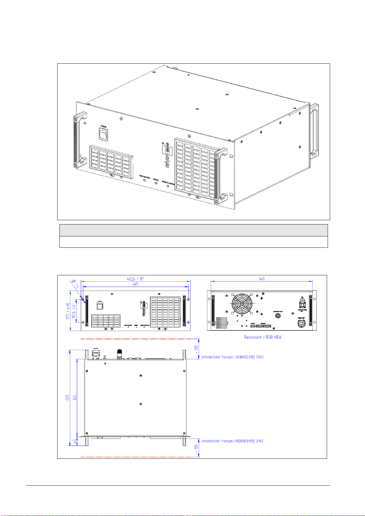
2.1 Overview of the machine...................................................................................................................6
2.2 Installation dimensions......................................................................................................................6
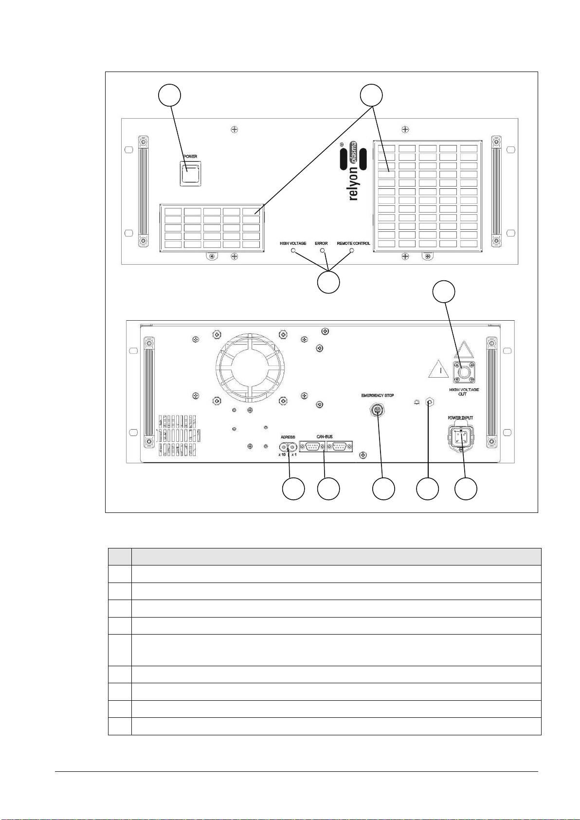
2.3 Description and connections.............................................................................................................7
2.4 Power connector pin assignment......................................................................................................8
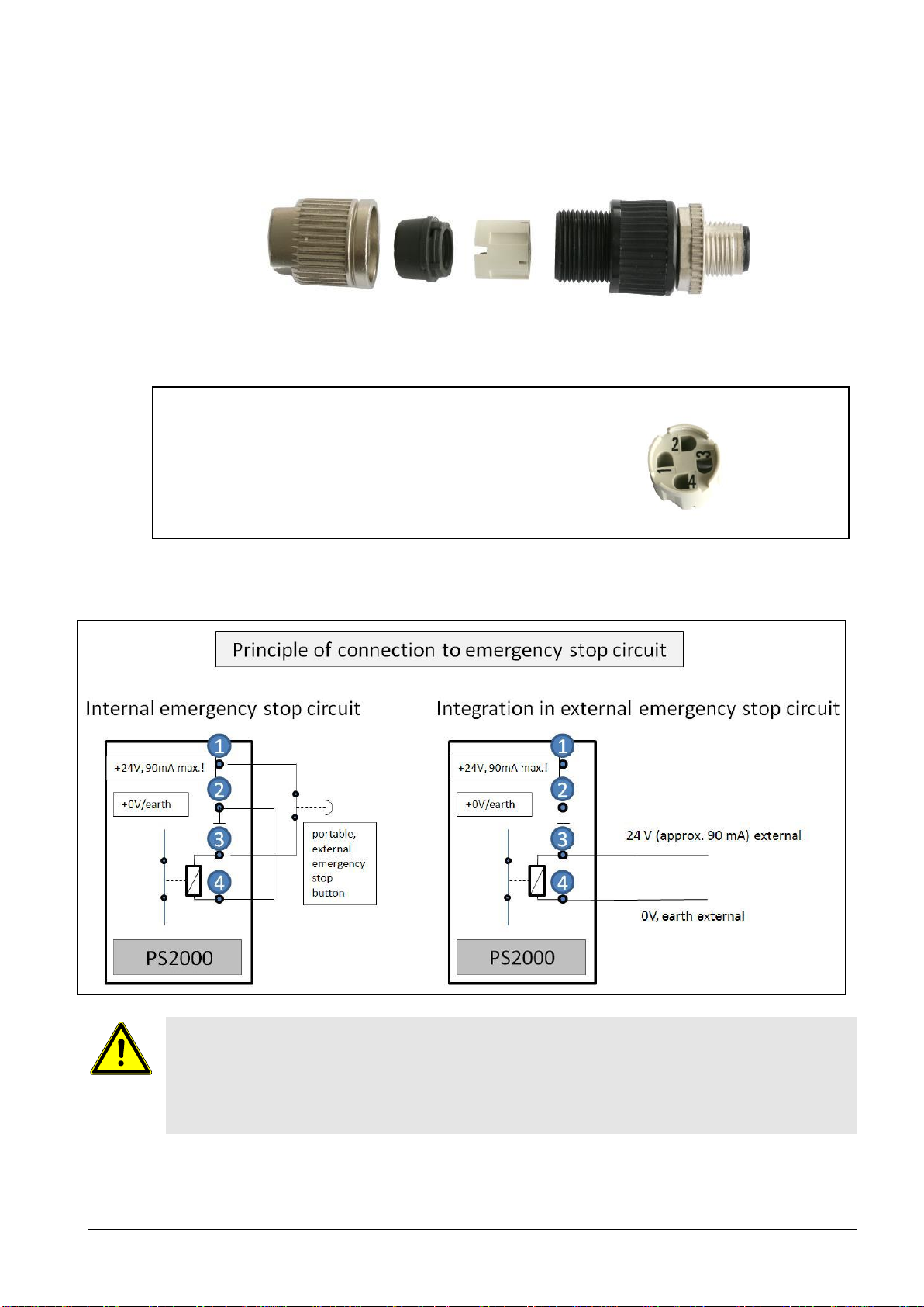
2.5 Pin assignment of emergency stop plug...........................................................................................9
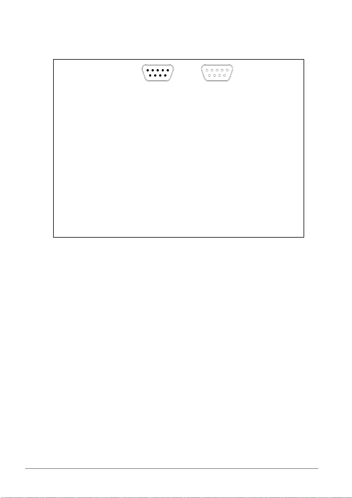
2.6 Pin assignment of CAN bus socket/plug (9-pin sub D socket/plug) ...............................................10
2.7 Scope of delivery.............................................................................................................................10
3Technical data.........................................................................................................................11
3.1 Technical data.................................................................................................................................11
3.2 Permissible operating parameters..................................................................................................11
4Transport/storage ...................................................................................................................12
5Unpacking and installation ....................................................................................................12
5.1 Unpacking .......................................................................................................................................12
5.2 Installation requirements.................................................................................................................12
5.2.1 Installing and starting up one single PS2000 ...................................................................12
5.2.2 Installing and starting up several PS2000s running in parallel.........................................14
6Operation.................................................................................................................................15
6.1 Controls / displays...........................................................................................................................15
6.2 Switching on and operating the machine........................................................................................15
6.2.1 Switching on and operating machine without bus communication...................................15
6.2.2 Switching on and operating machine with bus communication........................................16
6.3 Switching off the machine...............................................................................................................22
6.4 Error acknowledgement..................................................................................................................22
7Taking out of service ..............................................................................................................23
8Maintenance and cleaning .....................................................................................................24
8.1 Maintenance....................................................................................................................................24
8.2 Cleaning..........................................................................................................................................24
9Troubleshooting .....................................................................................................................25
9.1 Overview of faults / errors...............................................................................................................25
9.2 Customer service............................................................................................................................25
10 Environment............................................................................................................................26
10.1 Disposal ..........................................................................................................................................26
11 Conformity / standards...........................................................................................................26
11.1 CE ...................................................................................................................................................26
11.2 Product standards...........................................................................................................................26

4
June 2017
BA-PS2000_EN / F0307902
1Safety
The PS2000 power supply was designed in accordance with the relevant international
standards. However, as with any technical product, hazards may arise if the system is not
used properly or is used for purposes other than its intended use.
Working with the PS2000 power supply can be dangerous and may result in serious or fatal
injury. It is therefore essential to protect yourself and others.
In addition to the safety instructions in this document, you must also comply with general
safety standards.
Caution - Danger!
When working with the machine, please note and observe the safety instructions and
requirements in these operating instructions because non-compliance may result in
serious or fatal injury.
1.1 Residual risks
This machine has been manufactured in accordance with the current state of the art.
However, it is impossible to eliminate residual risks.
Always adhere to the following safety instructions:
Caution –electrical voltage!
•Danger from high voltage
- Never reach into the plasma beam of the connected plasma generator.
- During operation, never touch the workpiece in contact with the plasma beam or
the fixture that holds the workpiece.
- Never touch the connected plasma generator when the system is in operation.
- Never direct the plasma beam at people or animals.
- Earth the plasma generator by fitting in a holding fixture.
•Danger: 230 V. If damage is visible on the electrical connection, mains cable or
machine:
- Do not start up the machine.
- Replace the damaged parts or have them repaired by a qualified person.
Caution –Health hazard!
The machine operates at a high frequency (40 - 65 kHz in plasma generator).
•As a precaution, persons with a pacemaker or hearing aid should observe the
following:
- Do not use the PS2000 power supply near the pacemaker or hearing aid.
- Seek medical advice before working near the system.
•In hospitals and similar facilities, it is possible that the operation of the system may
impair the function of electrical medical equipment, computer equipment, or other
equipment
(such as ECG systems or PCs).
- Make sure that the operator of such equipment or systems is aware of this
possibility before starting up the machine.
Tripping hazard!
Lay connection cables such that they do not present a tripping hazard.

BA-PS2000_EN / F0307902
June 2017
5
Attention –damage to machine!
The machine may overheat. Do not cover the ventilation slots.
1.2 Information and obligations for the operator
•The system may emit interference.
- The system has been tested in accordance with EMC legislation.
- The operator must verify and assure electromagnetic compatibility with other
electrical and electronic equipment in the immediate vicinity of the system.
•Ensure that:
- Operating personnel have read and understood these operating instructions.
- Anyone working near the machine is made aware of the dangers and is provided
with the necessary protective equipment.
- Installations and repairs are only carried out by qualified persons.
•In particular, make operating personnel aware of the safety instructions in this
document.
•Always keep the system in fully functional condition.
•Any modifications made to the machine will invalidate the operating licence and the
warranty. Exception: Such modifications are expressly authorised by the manufacturer.
1.3 Intended use
The PS2000 power supply is only intended for operation of a plasma generator from
Relyon Plasma GmbH.
The machine is only intended for plasma surface treatment in combination with a suitable
plasma generator.
Under no circumstances may the machine be used by non-trained persons.
The machine is intended for installation in a control cabinet.
1.4 Impermissible operating conditions
The machine must not be operated under the following conditions:
•In explosive (EX) zones
•In areas with severe build-up of dust
•In environments where the humidity is too high (see technical data, page 11)
•At altitudes of more than 2,000 m above sea level
•Where there are strong vibrations

6
June 2017
BA-PS2000_EN / F0307902
2Description of machine
2.1 Overview of the machine
Component
PS2000 high-voltage power supply
2.2 Installation dimensions

BA-PS2000_EN / F0307902
June 2017
7
2.3 Description and connections
Fig.: Diagram of front (top) and rear (bottom) of the PS2000
No.
Component
1
Master switch I/O
2
Status LED
3
Ventilation grille with dust filter (class G2 coarse dust filter)
4
GES HB 30 PTFE high-voltage socket for connecting an HVC high-voltage cable
5
230 V AC, 50 Hz power connector (for cable type: H05V 3G1.5 CE (3 x 1.5mm²))
Harting HAN 3
6
Harting HAN M12 emergency stop plug connector
7
Communication (CAN bus) interface (sub D 9-pin) X21, X22
8
Address selector switch
9
Earthing connection
1
2
3
4
5
6
7
8
9

8
June 2017
BA-PS2000_EN / F0307902
2.4 Power connector pin assignment
The power connector comprises the following components:
1: Support sleeve
2: Panel jack
3: Retaining bolt (earthing function)
4: PG cable screw connection
Use a H05V 3G1.5 CE (3 x 1.5 mm²) cable to connect the power plug.
The panel jack pin assignment:
Fig. Pin assignment of mains voltage socket (left) and view of connection side (right)
Only the electricians responsible may connect the wires to the socket (plug assembly)!
PIN 1: L1
PIN 2: N
PIN 3: not connected
PE PIN: PE

BA-PS2000_EN / F0307902
June 2017
9
2.5 Pin assignment of emergency stop plug
The emergency stop plug supplied consists of 4 individual parts which have to be
plugged/screwed together as shown.
Pin assignment of the emergency stop plug:
Fig. Pin assignment of emergency stop plug (left) and view of self-tapping cable guide
(right)
24 V
If using an external voltage (integration in external emergency stop circuit), ensure that
the voltage is 24V DC (+/- 10%) (load: approx. 90 mA).
The output (pin 1-2) of the PS2000 must not be loaded with more than 90 mA under any
circumstances.
PIN 1: +24 V output
PIN 2: 0 V / GND output
PIN 3: +24 V input (+/- 10%)
PIN 4: 0 V input

10
June 2017
BA-PS2000_EN / F0307902
2.6 Pin assignment of CAN bus socket/plug (9-pin sub D socket/plug)
Fig.: Pin assignment of sub D socket/plug (left) and diagram of both interfaces (right).
2.7 Scope of delivery
The scope of delivery includes the following components:
•PS2000 power supply.
•Power connector for electrical connection of power supply (not mounted).
•Round plug connector for connecting and integrating the PS2000 in internal or external
emergency stop circuit (Harting HAN M12).
•Operating instructions.
Pin 1: 24 V input for external control (X21 & X22)
Pin 2: CAN Low (X21 & X22)
Pin 3: CAN Ground (X21 & X22)
Pin 4: GND input for external control (X21 & X22)
Pin 5: connected through (X21.5 ↔ X22.5 – no function)
Pin 6: connected through (X21.6 ↔ X22.6 – no function)
Pin 7: CAN High (X21 & X22)
Pin 8: not connected (X21 & X22)
Pin 9: connected through (X21.6 ↔ X22.6 – no function)
The CAN bus cable must be terminated at both ends with a terminator (120
ohms).
Fit a 120 ohm resistor between pin 2 (CAN Low) and pin 7 (CAN High) on X21
or X22 for this purpose.
5 4 3 2 1
9 8 7 6
5 4 3 2 1
9 8 7 6
X21
X22

BA-PS2000_EN / F0307902
June 2017
11
3Technical data
3.1 Technical data
Description
Value
Electrical data
Electrical connection
220 V –240 V AC / 50-60 Hz / max. 6 A
Mains fuse
F1 = 6.3 A / 230 V AC / time lag
Power consumption
≤ 1200 VA
Power loss
Pmax: 450 W
Protection
IP20 acc. to EN 60529
Protection class
Class I acc. to IEC 61140
Operating voltage of plasma
generator
•up to 20 kV Upeak (max. voltage for ignition (briefly))
•up to 2 kV RMS (average operating voltage)
Internal F1, F2 fuses
6.3 A / 500 V AC /time lag, SIBA type 189140.6.3
Dimensions
Weight
18.0 kg; 39.7 lbs
Dimensions
483 x 177 x 430 mm (corresponds to 4 HU); 19" x 6.97" x 16.93" (W
x H x D)
Operating conditions
Air humidity
< 80% rel. (non-condensing)
Temperature
0–40°C; 32 –104°F
Storage conditions
Air humidity
< 80% rel. (non-condensing)
Temperature
0 –60°C; 32 –140°F
Emissions
•Sound level
< 60 dB(A) at 1 metre away
•Waste heat
Pmax: 450 W
3.2 Permissible operating parameters
All system components of the plasma generator must be earthed.
During operation, the specified limits must be observed:
Description
Value
Plasma on
Before activating the high voltage for plasma generation, the gas
supply to the plasma generator must be switched on for at least 2
seconds.

12
June 2017
BA-PS2000_EN / F0307902
4Transport/storage
•Store the PS2000 power supply in a dry place. This will prevent the electrical contacts
from corroding.
•Protect the PS2000 power supply from dirt and foreign bodies.
5Unpacking and installation
Caution –electrical voltage!
Danger: 230 V and high voltage.
- Only electricians may connect the PS2000 power supply to the mains voltage supply
and connect the plasma generator and HVC cable extension to the PS2000 power
supply.
5.1 Unpacking
•Carefully open the PS2000 packaging. Note the information about directions provided
on the packaging.
•Take the PS2000 out of the packaging.
•After removing, check in particular the rear mains plug (see page 7, Part #6) to ensure
that the O-ring is positioned correctly in the socket.
5.2 Installation requirements
Before installing the machine, the following points must be met:
•The machine must be fully intact.
•If the PS2000 communicates with a superordinate control unit, the pins for the CAN
bus connection must be assigned following the requirements in these operating
instructions (see page 10).
•If installing as a permanent installation or in a building, a suitable switch or circuit
breaker that satisfies national safety requirements (in Germany: VDE 0100) must be
fitted as an upstream all-pole cut-off device that will disconnect the machine from the
power supply. This cut-off device should be fitted near the machine and must be easily
accessible to the user. The switch must also be labelled as the cut-off device for the
machine.
5.2.1 Installing and starting up one single PS2000
The PS2000 can be mounted horizontally or vertically. Ensure
a sufficient distance between the nearest housing wall and the
ventilation slots (>150 mm).

BA-PS2000_EN / F0307902
June 2017
13
To install the machine, perform the following steps in the specified order:
1. Mount the machine in a 19" control cabinet
intended for this purpose. Only use the
support rails on which the PS2000 is
mounted to distribute the weight.
- Use fixing bolts to secure the PS2000 in
the bracket. Use the four slots in the front
plate (#11) provided for this purpose.
- Please ensure sufficient space between the
control cabinet wall and front/rear (for
electrical connections, dissipation of heat).
This must not be any less than 150 mm.
2. Establish high-voltage connection between
HVC cable extension and connection
socket (#5) on the PS2000.
3. Mount an appropriate plasma generator.
Make sure that the screw connection is
hand tight.
4. Also earth the PS2000 at the earthing
connection (#10) (M5 thread)
5. Connect PS2000 with the emergency stop
circuit using the socket (#7).
6. Establish power supply to PS2000 (#6).
- 230 V / 50 Hz
Cable type: H05V 3x1.5 mm2
Please ensure a safe electrical connection
(especially PE conductor).
7. A CAN bus interface should be fitted with a
terminator for individual PS2000 operation
(see page 10)
The machine is installed.
11
5
6
10
7
8
9
11

14
June 2017
BA-PS2000_EN / F0307902
5.2.2 Installing and starting up several PS2000s running in parallel
To install and start up several PS2000s which are controlled in parallel by one control unit,
please proceed as follows:
1. Perform steps 1-6 for starting up an
individual PS2000
2. For each PS2000, set a separate
machine address on the rotary switch
(#9).
3. Connect all PS2000s in series with the
communication bus (#8).
Since there is a bus signal on both
ports (X21&X22), you can connect the
various PS2000s with one another.
Make sure that a suitable cable is used
for the connection between the
PS2000s.
Terminator
Please ensure that the CAN bus cable is terminated at both ends by a terminator (120
ohms) (resistor configuration / pin assignment: see page 10).
The machines are installed.
9
8

BA-PS2000_EN / F0307902
June 2017
15
6Operation
6.1 Controls / displays
Caution –electrical voltage!
Danger of electric shock.
- Never reach into the area around the connected plasma generator while it is running
or if it has shut down (e.g. to check why the plasma generator has shut down).
The PS2000 has LEDs indicating the current status.
No.
Display
Function
12
High Voltage
There is high voltage at the output of the connection socket (#5).
13
Error
There is an error present. It can be read off via the CAN bus.
PS2000 is not ready. The error must be acknowledged before the
machine can be operated again.
14
Remote Control
Communication with superordinate control unit possible. The current
source cannot be switched on in this operating mode via the 24 V
start signal.
6.2 Switching on and operating the machine
6.2.1 Switching on and operating machine without bus communication
Attention –damage to machine!
The machine must only be operated with the plasma generator connected.
The plasma generator may be damaged if it is operated with no gas or too little gas.
- Never switch on the high voltage before sufficient gas is flowing through the plasma
generator! Please comply with the information in the operating instructions for the
plasma generator.
12
13
14

16
June 2017
BA-PS2000_EN / F0307902
To switch on the PS2000 without bus communication, perform the following steps in the
order given:
1. Switch machine on using master switch (#1).
The master switch lights up green.
2. Ensure that a plasma generator is correctly connected to the PS2000 and that
sufficient gas is flowing through the plasma generator.
3. Connect 24 V at pin 1 to the plug X21 or X22 (GND is pin 4).
The machine is switched on.
If the machine is operated without bus communication, the electric parameters for plasma
generation cannot be changed. When supplied, the PS2000 is operated with the following
parameters: Frequency: 54 kHz, nominal output: 100%
6.2.2 Switching on and operating machine with bus communication
The PS2000 can be operated externally in two ways:
a. Via the "plasma control" software: This software is available from Relyon Plasma
GmbH and is used to control an individual PS2000.
This software and the appropriate CAN/USB converter can be used to change and log
operating parameters. Information about operating the PS2000 can be found in a
separate data sheet supplied with the software.
b. Via a control device produced by the customer. The CANopen protocol is based on the
CIA301 specification. The object directory and linked information are described below.
6.2.2.1 CANopen object directory for control device produced by the customer
Index
hex
Sub-
Index
hex
Name (reference)
Attribut
e
Mappa
ble
Object
type
Data type
Default value
Comment
1000
00
Device type
ro
n
VAR
UNSIGNED32
0x00000000
1001
00
Error register
ro
y
VAR
UNSIGNED8
0x00
See "Error
message"
1003
Pre-defined error
field
ARRAY
UNSIGNED32
00
Number of errors
rw
n
UNSIGNED8
00h
01
Standard error field
ro
n
UNSIGNED32
0000 0000h
02
Standard error field
ro
n
UNSIGNED32
0000 0000h
03
Standard error field
ro
n
UNSIGNED32
0000 0000h
04
Standard error field
ro
n
UNSIGNED32
0000 0000h
1005
00
COB-ID SYNC
message
rw
n
VAR
UNSIGNED32
0000 0080h
1008
00
Manufacturer
device name
ro
n
VAR
VISIBLE_STRI
NG
“PS2000”
1009
00
Manufacturer
hardware version
ro
n
VAR
VISIBLE_STRI
NG
hardware
version string,
100A
00
Manufacturer
software version
ro
n
VAR
VISIBLE_STRI
NG
software
version string,
e.g. “V01.00”
100C
00
Guard time
rw
n
VAR
UNSIGNED16
0000h
0..32000 [ms]
100D
00
Life time factor
rw
n
VAR
UNSIGNED8
00h
0..255 [factor] for
guard time

BA-PS2000_EN / F0307902
June 2017
17
Index
hex
Sub-
Index
hex
Name (reference)
Attribut
e
Mappa
ble
Object
type
Data type
Default value
Comment
1010
Store parameters
ARRAY
UNSIGNED32
00
Highest sub-index
supported
ro
n
UNSIGNED8
04h
01
Save all
parameters
rw
n
UNSIGNED32
0000 0001h
Ascii “save“
Complete object
directory (incl.
2040-2043) is
saved
02
Save
communication
parameters
rw
n
UNSIGNED32
0000 0000h
"save" not
supported
03
Save application
parameters
rw
n
UNSIGNED32
0000 0000h
"save" not
supported
04
Save manufacturer
defined parameters
rw
n
UNSIGNED32
0000 0001h
"Burn in" set of
parameters - Only
objects 2040-
2043 are saved
1011
Restore
parameters
ARRAY
UNSIGNED32
00
Highest sub-index
supported
ro
n
UNSIGNED8
00h
01
Restore all
parameters
rw
n
UNSIGNED32
0000 0001h
Ascii “load“
Complete object
directory (NOT
INCLUDING
2040-2043) is
deleted.
02
Restore
communication
parameters
rw
n
UNSIGNED32
0000 0000h
"load" not
supported
03
Restore application
parameters
rw
n
UNSIGNED32
0000 0000h
"load" not
supported
04
Restore
manufacturer
defined parameters
rw
n
UNSIGNED32
0000 0001h
"Burn in" set of
parameters is
reset to factory
settings
1014
00
COB-ID emergency
message
rw
n
VAR
UNSIGNED32
80h+ node ID
1016
Consumer
heartbeat time
ARRAY
00
Highest sub-index
supported
ro
n
UNSIGNED8
03h
01
Consumer
heartbeat time
rw
n
UNSIGNED32
0000 0000h
0..32000[ms]
02
Consumer
heartbeat time
rw
n
UNSIGNED32
0000 0000h
0..32000[ms]
03
Consumer
heartbeat time
rw
n
UNSIGNED32
0000 0000h
0..32000[ms]
1017
00
Producer heartbeat
time
rw
n
VAR
UNSIGNED16
0000h
1018
Identity object
RECORD
IDENTITY
00
Highest sub-index
supported
ro
n
UNSIGNED8
04h

18
June 2017
BA-PS2000_EN / F0307902
Index
hex
Sub-
Index
hex
Name (reference)
Attribut
e
Mappa
ble
Object
type
Data type
Default value
Comment
01
Vendor ID
ro
n
UNSIGNED32
0000 0000h
(Bosch
Rexroth AG
Pneumatics
–ship
engineering)
02
Product code
ro
n
UNSIGNED32
0000 0000h
03
Revision number
ro
n
UNSIGNED32
0000 0000h
04
Serial number
ro
n
UNSIGNED32
FFFF FFFFh
1200
SDO server 1
parameter
RECORD
SDO_PARAME
TER
00
Highest sub-index
supported
ro
n
UNSIGNED8
02h
01
COB ID client ->
server (rx)
ro
n
UNSIGNED32
0000 0600h+
Node ID
02
COB ID server ->
client (tx)
ro
n
UNSIGNED32
0000 0580h+
Node ID
1400
RPDO 1 comm.
parameter
RECORD
PDO_COMMU
NICATION_PA
RAMETER
00
Highest sub-index
supported
ro
n
UNSIGNED8
02h
01
COB ID used by
RPDO
rw
n
UNSIGNED32
0000 0200h+
Node ID
02
Transmission type
rw
n
UNSIGNED8
FFh
“FF”
asynchronous;
“1” synchronous
See CIA301
1600
RPDO 1 mapping
parameter
RECORD
PDO_MAPPIN
G
00
Number of mapped
application objects
in RPDO
ro
n
UNSIGNED8
Number of
mapped objects
(digital outputs)
5
01
1st application
object
ro
n
UNSIGNED32
2030 00 08
02
2nd application
object
ro
n
UNSIGNED32
2040 00 08
03
3rd application
object
ro
n
UNSIGNED32
2041 00 10
04
4th application
object
ro
n
UNSIGNED32
2042 00 10
05
5th application
object
ro
n
UNSIGNED32
2043 00 10
1800
TPDO 1 comm.
parameter
RECORD
PDO_COMMU
NICATION_PA
RAMETER
00
Highest sub-index
supported
ro
n
UNSIGNED8
05h
01
COB ID used by
TPDO
rw
n
UNSIGNED32
0000 0180h+
Node ID
02
Transmission type
rw
n
UNSIGNED8
FFh
03
Inhibit time
rw
n
UNSIGNED16
0000h
See CIA301
0..32000 [ms]
05
Event timer
rw
n
UNSIGNED16
0000h
See CIA301
0..32000 [ms]

BA-PS2000_EN / F0307902
June 2017
19
Index
hex
Sub-
Index
hex
Name (reference)
Attribut
e
Mappa
ble
Object
type
Data type
Default value
Comment
1A00
TPDO 1 mapping
parameter
RECORD
PDO_MAPPIN
G
00
Number of mapped
application objects
in TPDO
ro
n
UNSIGNED8
Number of
mapped objects
(digital inputs)
5
01
1st application
object
ro
n
UNSIGNED32
2010 00 08
02
2nd application
object
ro
n
UNSIGNED32
2020 00 08
03
3rd application
object
ro
n
UNSIGNED32
2021 00 10
04
4th application
object
ro
n
UNSIGNED32
2022 00 10
05
5th application
object
ro
n
UNSIGNED32
2023 00 10
1F51
Program control
Array
UNSIGNED8
00
Highest sub-index
supported
ro
n
UNSIGNED8
1
01
Program 1
rw
n
UNSIGNED8
Internal use - do
not change!
2000
00
Error status
rw
n
VAR
UNSIGNED8
0 Rw: Delete
error statuses,
see "Error
message"
RPDO2; Byte1
2010
00
Status code
ro
j
VAR
UNSIGNED8
See “Status
code”; TPDO1;
Byte1
2020
00
Power actual
ro
j
VAR
UNSIGNED16
TPDO1; Byte3,4
2021
00
Frequency actual
ro
j
VAR
UNSIGNED8
TPDO1; Byte2
2022
00
Voltage RMS
actual
ro
j
VAR
UNSIGNED16
TPDO1; Byte5,6
2023
00
Current RMS actual
ro
j
VAR
UNSIGNED16
TPDO1; Byte7,8
2030
00
High Voltage
rw
j
VAR
UNSIGNED8
Write: 0/1
Read:
Corresponding
status code
0x2010
(PlasmaOk)
RPDO1; Byte1
2040
00
Power set
rw
j
VAR
UNSIGNED8
0..100;
RPDO1;Byte2
2041
00
Frequency set
rw
j
VAR
UNSIGNED16
RPDO1; Byte3,4
2042
00
Voltage threshold
rw
j
VAR
UNSIGNED16
Internal error
threshold - do not
change!
RPDO1; Byte5,6
2043
00
Current threshold
rw
j
VAR
UNSIGNED16
Internal error
threshold - do not
change!
RPDO1; Byte 7,8
2050
Temperature
Array
00
Highest sub-index
supported
ro
n
UNSIGNED8
5
01
Temperature 1
ro
n
UNSIGNED8
TPDO2; Byte3

20
June 2017
BA-PS2000_EN / F0307902
Index
hex
Sub-
Index
hex
Name (reference)
Attribut
e
Mappa
ble
Object
type
Data type
Default value
Comment
02
Temperature 2
ro
n
UNSIGNED8
TPDO2; Byte4
03
Temperature 3
ro
n
UNSIGNED8
TPDO2; Byte5
04
Temperature 4
ro
n
UNSIGNED8
TPDO2; Byte6
05
Temperature 5
ro
n
UNSIGNED8
2060
00
Power-On time
ro
n
VAR
UNSIGNED16
TPDO02; Byte1,2
2100
00
Internal use
wo
n
VAR
UNSIGNED32
Do not change!
2110
00
Internal use
ro
n
VAR
UNSIGNED16
•Please always ensure that the operating parameters of the PS2000 are within the
stated range of values:
Description
Adjustable value
Default values ("Burn in"
set of parameters)
Frequency set [Hz]
40000-65000 (step width 200 Hz)
54000 Hz
Power set [%]
70-100 (step width 1)
100%
Voltage threshold [V]
Internal error threshold - do not
change!
500 V
Current threshold [mA]
Internal error threshold - do not
change!
100 mA
•Standard baud rate: 500 kbit/s. Baud rate can be changed via LSS protocol (defined
using CIA305). Supported baud rates: 1 Mbit/s, 500 kbit/s, 250 kbit/s, 125 kbit/s
•"Remote control" LED: To visualise communication via an illuminated "Remote
control" LED, the "Operational" status must be set once in the CANopen State
Machine (network management command: 0x00 0x01 + corresponding node
number of the PS2000 (reset to "preoperational": 0x00 0x80)).
•The communication status should be continuously monitored via the "Guard" or
"Heartbeat" telegram! If there is no communication, the PS2000 must switch off the
high voltage!
Attention –Safety!
We would highly recommend querying and monitoring the "Guard" or "Heartbeat"
telegram so that the PS2000 can still be switched in the event of e.g. loss of
communication with the superordinate control unit.
Attention –damage to machine!
Please only change the approved parameters! If incorrectly actuated, the PS2000 may
develop serious faults or be destroyed.
Table of contents