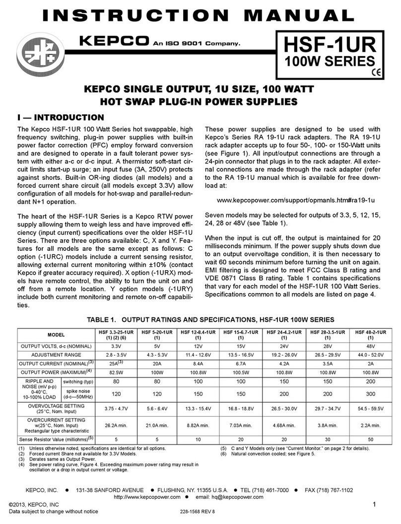
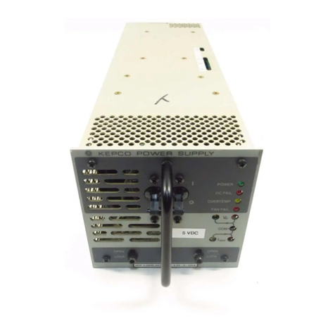
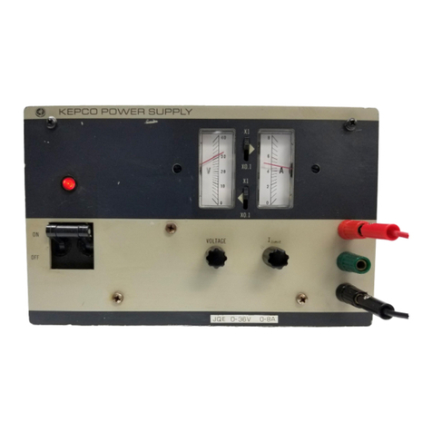
KEPCO JQE 25-20MVPY-27274 User manual

MODEL
INSTRUCTION MANUAL
IMPORTANT NOTES:
1) This manual is valid for the following Model and associated serial numbers:
MODEL SERIAL NO. REV. NO.
2) A Change Page may be included at the end of the manual. All applicable changes and
revision number changes are documented with reference to the equipment serial num-
bers. Before using this Instruction Manual, check your equipment serial number to identify
your model. If in doubt, contact your nearest Kepco Representative, or the Kepco Docu-
mentation Office in New York, (718) 461-7000, requesting the correct revision for your
particular model and serial number.
3) The contents of this manual are protected by copyright. Reproduction of any part can be
made only with the specific written permission of Kepco, Inc.
Data subject to change without notice.
KEPCO®
THE POWER SUPPLIER™
ORDER NO. REV. NO.
KEPCO, INC. z131-38 SANFORD AVENUE zFLUSHING, NY. 11355 U.S.A. zTEL (718) 461-7000 zFAX (718) 767-1102
email: hq@kepcopower.com zWorld Wide Web: http://www.kepcopower.com
KEPCO INC.
An ISO 9001 Company.
©2011, KEPCO, INC.
P/N 243-1333-b
JQE 25-20MVPY-27274
POWER SUPPLY
JQE 25-20MVPY-27274
POWER SUPPLY
INSTRUCTION MANUAL


228-1348 DC-COMP/INST 092611 A
Declaration of Conformity
Application of Council directives: 73/23/EEC (LVD)
93/68/EEC (CE mark)
Standard to which Conformity is declared:
EN61010-1:2001 (Safety requirements for electrical equipment for measurement,
control and laboratory use - Part 1)
Manufacturer's Name and Address: KEPCO INC.
131-38 SANFORD AVENUE
FLUSHING, N.Y. 11352 USA
Importer's Name and Address:
Type of Equipment: Component Power Supply
Model No.: [PRODUCT MODEL NUMBER]
Year of Manufacture:
I, the undersigned, declare that the product specified above, when used in conjunction with the condi-
tions of conformance set forth in the product instruction manual, complies with the requirements of the
Low Voltage Directive 73/23/EEC, which forms the basis for application of the CE Mark to this product.
Place: KEPCO Inc.
131-38 Sanford Ave.
Flushing, N.Y.11352 USA
Date:
Saul Kupferberg
(Full Name)
VP OF SALES
(position)
REPRESENTATIVECOPY

B228-1351 COND/CONFORM 092611
Conditions of Conformance
When this product is used in applications governed by the requirements of the EEC, the following restric-
tions and conditions apply:
1. For European applications, requiring compliance to the Low Voltage Directive, 73/23/EEC, this power
supply is considered a component product, designed for “built in“ applications. Because it is incom-
plete in construction, the end product enclosure must provide for compliance to any remaining electri-
cal safety requirements and act as a fire enclosure. (EN61010-1:2001, Cl. 6, Cl. 7, Cl.8, and Cl. 9)
2. This power supply is designed for stationary installation, with mains power applied via a detachable
power supply cord or via direct wiring to the source power terminal block.
3. This power supply is considered a Class 1 (earthed) product. It is intended for use as part of equip-
ment meant for test, measurement and laboratory use, and is designed to operate from single phase,
three wire power systems. This equipment must be installed within a suitably wired equipment rack,
utilizing a three wire (grounded) mains connection. See wiring section of this manual for complete
electrical wiring instructions. (EN61010-1:2001, Cl.6.10.1)
4. This power supply has secondary output circuits that are considered hazardous, and which exceed
180W output power at a potential of 2V or more.
5. The output wiring terminals of this power supply has not been evaluated for field wiring and, therefore,
must be properly configured by the end product manufacturer prior to use.
6. This power supply employs a supplementary circuit protector in the form of a circuit breaker mounted
on the front panel. This circuit breaker protects the power supply itself from damage in the event of a
fault condition. For complete circuit protection of the end product, as well as the building wiring, it is
required that a primary circuit protection device be fitted to the branch circuit wiring. (EN61010-1:2001,
Cl. 9.5)
7. Hazardous voltages are present within this power supply during normal operation. All operator adjust-
ments to the product are made via externally accessible switches, controls and signal lines as speci-
fied within the product operating instructions. There are no user or operator serviceable parts within
the product enclosure. Refer all servicing to qualified and trained Kepco service technicians.

228-1352 SAFETY - (COVER REMOVAL) 092611 C/(D BLANK)
SAFETY INSTRUCTIONS
1. Installation, Operation and Service Precautions
This product is designed for use in accordance with EN 61010-1 and UL 3101 for Installation Category 2,
Pollution Degree 2. Hazardous voltages are present within this product during normal operation. The prod-
uct should never be operated with the cover removed unless equivalent protection of the operator from
accidental contact with hazardous internal voltages is provided:
2. Grounding
This product is a Class 1 device which utilizes protective earthing to ensure operator safety.
3. Electric Shock Hazards
This product outputs hazardous voltage and energy levels as a function of normal operation. Operators
must be trained in its use and exercise caution as well as common sense during use to prevent accidental
shock.
There are no operator serviceable parts or adjustments within the product enclosure.
Refer all servicing to trained service technician.
Source power must be removed from the product prior to performing any servicing.
This product is factory-wired for the nominal a-c mains voltage indicated on the rat-
ing nameplate located adjacent to the source power connection on the product's rear
panel. To reconfigure the product input for other nominal mains voltages as listed
herein, the product must be modified by a trained service technician.
The PROTECTIVE EARTHING CONDUCTOR TERMINAL must be properly con-
nected prior to application of source power to the product (see instructions on instal-
lation herein) in order to ensure safety from electric shock.
PROTECTIVE EARTHING CONDUCTOR TERMINAL - This symbol indicates the
point on the product to which the protective earthing conductor must be attached.
EARTH (GROUND) TERMINAL - This symbol is used to indicate a point which is
connected to the PROTECTIVE EARTHING TERMINAL. The component installer/
assembler must ensure that this point is connected to the PROTECTIVE EARTH-
ING TERMINAL.
CHASSIS TERMINAL -This symbol indicates frame (chassis) connection, which is
supplied as a point of convenience for performance purposes (see instructions on
grounding herein). This is not to be confused with the protective earthing point, and
may not be used in place of it.
This symbol appears adjacent to any external terminals at which hazardous voltage
levels as high as 500V d-c may exist in the course of normal or single fault condi-
tions.
This symbol appears adjacent to any external terminals at which hazardous voltage
levels in excess of 500V d-c may exist in the course of normal or single fault condi-
tions.
!
!
!
!
!


27274092611 i
TABLE OF CONTENTS
SECTION PAGE
SECTION 1 - INTRODUCTION
1.1 Scope of Manual ..................................................................................................................................... 1-1
1.2 General Description................................................................................................................................. 1-1
1.3 Features. ................................................................................................................................................. 1-1
1.4 Accessories ............................................................................................................................................. 1-2
1.5 Specifications .......................................................................................................................................... 1-2
1.6 Specifications, Mechanical ...................................................................................................................... 1-4
SECTION 2 - INSTALLATION
2.1 Unpacking and Inspection ....................................................................................................................... 2-1
2.2 Terminations............................................................................................................................................ 2-1
2.3 AC Input Requirements ........................................................................................................................... 2-3
2.4 Cooling .................................................................................................................................................... 2-4
2.5 Preliminary Operational Check................................................................................................................ 2-4
2.6 Installation ............................................................................................................................................... 2-5
2.7 Grounding................................................................................................................................................ 2-5
SECTION 3 - OPERATION
3.1 Standard Power Supply Operation, Local Control................................................................................... 3-1
3.1.1 General.............................................................................................................................................. 3-1
3.2 Load Connection ..................................................................................................................................... 3-1
3.2.1 Local Error Sensing ........................................................................................................................... 3-1
3.2.2 Remote Error Sensing ....................................................................................................................... 3-2
3.2.3 Grounded Load Connection............................................................................................................... 3-2
3.3 Output Adjustment................................................................................................................................... 3-3
3.4 Introduction to Remote Programming ..................................................................................................... 3-3
3.4.1 General.............................................................................................................................................. 3-3
3.4.2 Equations Showing the Operation of the Kepco Bridge..................................................................... 3-5
3.5 General Rules for Remote Programming ................................................................................................ 3-6
3.5.1 Grounding.......................................................................................................................................... 3-6
3.5.2 Connections....................................................................................................................................... 3-6
3.5.3 Programming Resistors ..................................................................................................................... 3-6
3.5.4 External Switching ............................................................................................................................. 3-6
3.6 Output Voltage Programming With External Resistance......................................................................... 3-6
3.7 Constant Current Operation .................................................................................................................... 3-7
SECTION 4 - CALIBRATION
4.1 General.................................................................................................................................................... 4-1
4.2 Test Equipment Required........................................................................................................................ 4-1
4.3 Output Voltage Calibration ...................................................................................................................... 4-1
4.3.1 Voltage Pre-calibration Setup ............................................................................................................ 4-1
4.3.2 Zero Output Voltage Calibration ........................................................................................................ 4-2
4.3.2.1 Zero Output Voltage (Local Programming) Calibration................................................................ 4-2
4.3.2.2 Zero Output Voltage (Remote Programming) Calibration............................................................ 4-2
4.3.3 Zero VOLTAGE Monitor Calibration .................................................................................................. 4-2
4.3.4 Zero CURRENT Monitor Calibration.................................................................................................. 4-3
4.3.5 Local Full Scale (FS) Output Voltage Calibration .............................................................................. 4-3
4.3.6 Remote Full Scale (FS) Output Voltage Calibration .......................................................................... 4-3
4.3.7 Full Scale (FS) VOLTAGE Monitor Calibration.................................................................................. 4-3
4.4 Output Current Limit calibration............................................................................................................... 4-4
4.4.1 Current Limit Pre-calibration Setup.................................................................................................... 4-4
4.4.2 Full Scale (maximum) Output Current Limit Calibration .................................................................... 4-4
4.4.3 FS Current Monitor Calibration.......................................................................................................... 4-4
4.4.4 Minimum Output Current Check ........................................................................................................ 4-5
4.5 Overvoltage Protection (OVP) Test and Adjustment............................................................................... 4-5
ii 27274092611
TABLE OF CONTENTS
SECTION PAGE
SECTION 5 - THEORY OF OPERATION
5.1 Simplified Diagram Discussion ............................................................................................................... 5-1
5.2 Circuit Description................................................................................................................................... 5-1
5.2.1 A-C Input Circuit................................................................................................................................ 5-1
5.2.2 Main d-c Supply ................................................................................................................................ 5-3
5.2.3 Pass-Element Section....................................................................................................................... 5-3
5.2.4 Voltage Error Amplifier (VEA) ........................................................................................................... 5-3
5.2.5 Current Limit Circuit (CEA) ............................................................................................................... 5-4
5.2.6 Overvoltage Protection Circuit and Current Monitor ......................................................................... 5-4
5.2.7 Auxiliary Supplies.............................................................................................................................. 5-4
5.2.8 Metering Circuit................................................................................................................................. 5-5
5.2.9 Monitoring Circuit .............................................................................................................................. 5-5
SECTION 6 - MAINTENANCE
6.1 General ................................................................................................................................................... 6-1
6.2 Disassembly/Reassembly....................................................................................................................... 6-1
6.2.1 Cover Removal ................................................................................................................................. 6-1
6.2.2 A1 Circuit Board Removal................................................................................................................. 6-1
6.2.3 A5 Terminal Block Board and CR203 and CR204 Access ............................................................... 6-2
6.2.4 A3 Heat Sink Removal...................................................................................................................... 6-2
6.2.5 A4 Overvoltage Protection Circuit Board Removal ........................................................................... 6-2
6.2.6 Reassembly. ..................................................................................................................................... 6-2
6.3 Troubleshooting ...................................................................................................................................... 6-2
6.4 Power Supply Measurements................................................................................................................. 6-4
6.4.1 Required Test Equipment. ................................................................................................................ 6-4
6.4.2 Measurement Instructions................................................................................................................. 6-5
SECTION 7 - ELECTRICAL PARTS LIST AND DIAGRAMS
7.1 General ................................................................................................................................................... 7-1
7.2 Ordering Information............................................................................................................................... 7-1
7.3 Abbreviations Used in Kepco Parts Lists................................................................................................ 7-2
7.3.1 Reference Designators ..................................................................................................................... 7-2
7.3.2 Descriptive Abbreviations ................................................................................................................. 7-2

LIST OF FIGURES
FIGURE TITLE PAGE
27274092611 iii
1-1 Mechanical Outline Drawing ....................................................................................................................... 1-5
2-1 Front Panel Controls and Indicators, JQE Special Models ......................................................................... 2-1
2-2 Rear Panel Terminations, JQE Special Models .......................................................................................... 2-2
2-3 Location of Internal Adjustments ................................................................................................................ 2-3
2-4 Conversion to 230V AC Line Operation ...................................................................................................... 2-4
3-1 Load Connection Showing a Floating Load ................................................................................................ 3-1
3-2 Grounded Load Connections ...................................................................................................................... 3-2
3-3 Comparison Bridge (Simplified) for Voltage Mode ...................................................................................... 3-4
3-4 Comparison Bridge (Simplified) for Current Mode ...................................................................................... 3-4
3-5 Remote Resistance Programming (Voltage Mode)..................................................................................... 3-7
5-1 JQE Special Power Supply, Simplified Schematic Diagram ....................................................................... 5-2
6-1 A1 PC Board, Reassembly ......................................................................................................................... 6-1
7-1 JQE 25-20MVPY-27274 Power Supply, Component Locations ................................................................. 7-3
7-2 JQE 25-20MVPY-27274 A1 Assembly, Component Locations................................................................... 7-6
7-3 JQE 25-20MVPY-27274 A3 Assembly, Component Locations................................................................... 7-11
7-4 JQE 25-20MVPY-27274 A3A1 Assembly, Component Locations .............................................................. 7-12
7-5 JQE 25-20MVPY-27274 A3A2 Assembly, Component Locations .............................................................. 7-13
7-6 JQE 25-20MVPY-27274 A4 Assembly, Component Locations................................................................... 7-14
7-7 JQE 25-20MVPY-27274, Overall Schematic Diagram................................................................................ 7-17
7-8 Amplifier and Reference Board A1, Schematic Diagram ............................................................................ 7-19
7-9 Overvoltage Protection Board A4, Schematic Diagram .............................................................................. 7-21

iv 27274092611
LIST OF TABLES
TABLE TITLE PAGE
1-1 JQE 25-20MVPY-27274 Specifications ...................................................................................................... 1-2
2-1 Front Panel Controls and Indicator Functions ............................................................................................ 2-1
2-2 Rear Panel Termination Functions ............................................................................................................. 2-2
2-3 Internal Adjustments ................................................................................................................................... 2-3
6-1 Auxiliary Supply Voltages ........................................................................................................................... 6-3

JQE 27274 092611 1-1
SECTION 1 - INTRODUCTION
1.1 SCOPE OF MANUAL
This manual contains instructions for the installation, operation and maintenance of the specially
modified Kepco JQE 25-20MVPY-27274, “HALF-RACK” Power Supply, manufactured by Kepco,
Inc., Flushing, New York, U.S.A. This model is hereafter referred to as JQE Special Power Supply
or JQE Special. Additional copies of this manual can be downloaded from the Kepco web site at
http://www.kepcopower.com/support/opmanls.htm#jqe.
1.2 GENERAL DESCRIPTION
The Kepco JQE Special Power Supply is a unipolar, linear, precision regulated voltage source in
a half-rack configuration. The power supply has a rectangular voltage-current limit output char-
acteristic. It features full range voltage control, from zero to the nominal output voltage value,
and current limit control, from a small offset of 0.5% of nominal output current to the nominal
output current value. The JQE can be operated as either a voltage source or a current source.
The input source power is an a-c line, single phase, either 115V or 230V a-c (nominal) value.
The nominal a-c input value is established by changing some jumpers on the power trans-
former's terminal block.
The JQE Special power supply has linear, full-dissipation series-regulators (NPN) driven by an
integrated circuit operational amplifier. A sharp current-limit circuit enables current control oper-
ation of the power supply. The output voltage of the JQE power supply can be programmed
remotely. All necessary connections are available on terminals at the rear barrier-strip.
The compact design of the JQE Specials was made possible by a unique heatsink design of
exceptional efficiency in combination with highly reliable low-noise fans. All JQE power supplies
feature all-silicon design with conservatively rated components for added reliability.
1.3 FEATURES.
The JQE Special includes the following features:
a) Two panel meters which permit simultaneous monitoring of the output voltage and out-
put current.
b) Overvoltage Protection. This protection acts simultaneously on the circuit breaker’s volt-
age coil and the electrical “crowbar” that shorts the output through a silicon-controlled
rectifier (SCR) if the output voltage exceeds a preadjustable limit on the sensing lines
(see Table 1-1 for specifications).
c) Zero and full scale voltage calibration for local front panel voltage control.
d) Full scale current calibration for CURRENT LIMIT.
e) Zero and full scale current calibration for VOLTAGE MONITOR
f) Zero and full scale current calibration for CURRENT MONITOR
The main chassis frame of the power supply is constructed from cold-rolled steel, as is the per-
forated wrap-around cover. Front panel material is aluminum (Refer to FIG. 1-3 for finish).

1-2 JQE 27274 092611
1.4 ACCESSORIES
a) RACK ADAPTOR (for two units); Kepco Model RA 24. Fits standard EIA rack-dimen-
sions.
b) FILLER PANEL, to cover empty slot if RA 24 is used for one unit only: Kepco Model RFP
24-2.
1.5 SPECIFICATIONS
TABLE 1-1. JQE 25-20MVPY-27274 SPECIFICATIONS
SPECIFICATION RATING/DESCRIPTION CONDITIONS/NOTES
A-C Input Voltage nominal 115/230V a-c Single Phase.
range 105-125/210-250V a-c Selectable by changing internal
jumpers
Frequency nominal 50/60 Hz
Range 47-63 Hz
Input Current 11A a-c max. @ 125V a-c
6A a-c max. @ 250 a-c
Isolation to Chassis 500V d-c or peak Max. between either output ter-
minal and Chassis
Leakage Current 115 Va-c 5 µArms / 50 µAp-p Between output and Chassis
Insulation coordination Input Installation Category II,
Overvoltage Category II
For TN power system
Output Installation Category II,
Overvoltage Category II
Max. 500 Vd-c or peak between
output and Chassis
Pollution degree 2
Type of stabilizer Linear, 1-quadrant, rectangular V-I
Output Voltage
(Voltage mode)
Range 0 to +25V d-c Using a 10-turn front panel
potentiometer. Factory default
setting is 0V.
Resolution 0.05% of nominal
Accuracy 0.1% of nominal
Source effect 0.005% of nominal For 105-125 / 210-250V a-c
Load effect 0.005% of nominal No load- Full load
Time effect 0.05% of nominal 8 Hrs, FS(1), full load
Temperature coefficient 0.01% of nominal/°C 0 to +50°C. FS(1), full load
Ripple & noise 0.2 mVrms / 10mVp-p FS(1), full load, local sensing
Output Current
(Current Limit mode)
Range +0.1 to +20A d-c Using a 10-turn front panel
potentiometer. Factory default
setting is 20A
Resolution 0.05% of nominal
Accuracy 0.1% of nominal
Source effect 0.01% of nominal For 105-125 / 210-250V a-c,
short circuit at output
Load effect 0.05% of nominal Short circuit - Full load
Time effect 0.05% of nominal 8 Hrs, FS(2), short circuit at out-
put
Temperature coefficient 0.02% of nominal/°C 0 to +50°C. FS(2), full load
Ripple & noise 0.05% of nominal rms/
0.2% of nominal p-p
FS(2), short circuit, nominal
value
(1) Zero and FS (full scale) calibration adjustments accessible through top cover.
(2) FS (full scale) calibration adjustment accessible through top cover.

JQE 27274 092611 1-3
Output Power 500W
Output Impedance Voltage Mode 63 µOhms / 0.5 µH
Current Mode 25KOhms / 5.8 mF
Voltage Recovery Time 50µS max With load between No load and
Full load, Output voltage in Volt-
age mode.
Voltage Overshoot N/A For turn on/turn off: above 25%
of nominal setting; Below 25%:
negligible for load above 10% of
nominal.
Current Recovery Time Constant (Rload)(Cout)C
out = 5.8mF; With load between
full load and short circuit.
Protections Input Overcurrent All protections trip the input circuit breaker
to OFF.
Pass element Heatsink
Overtemperature
Output Overvoltage (OVP)
Overvoltage Protection Adjustable Range 5% to 130% of nominal output voltage
value
Factory default setting is maxi-
mum value.
Threshold Accuracy 0.5V
Adjustable triggering delay 25 ±5 to 180 ± 40 µSec Middle value as default.
Triggering time 5 - 10µSec
Display Analog meters for Output Voltage and
Current, with 3% accuracy
2-inch recessed panel meters,
one for output voltage, one for
output current
Isolated Remote
monitoring signals
for Output Voltage
and Current
Range 0 to +10V(1) for zero to nominal output
voltage and current
Monitoring signals are isolated
from power supply output termi-
nals and chassis (500V
d-c max. or peak)
Accuracy 0.1% for voltage monitoring,
0.2% for current monitoring
Output impedance 100 Ohms
Output current 5 mA max.
Output Ripple voltage monitor: 0.5mVrms in voltage mode
current monitor: 1.0mVrms in current mode
Remote voltage sensing Kelvin connection for remote sensing with
max 1.0V per load-wire
Remote programming
time
Depends on load value, internal output
capacitor (5.8 mF) and current limit setting
Cooling Air forced cooling, using an a-c fan with low
noise non-metal blade
Intake from top, sides and bot-
tom; needs at least 1 in. on top
and/or sides for cooling; exhaust
to rear
Operating temperature range 0 to +50°C
Storage temperature
range
-25 to +85°C
Altitude Operating from sea level to 10,000 feet
(1) Zero and FS (full scale) calibration adjustments accessible through top cover.
TABLE 1-1. JQE 25-20MVPY-27274 SPECIFICATIONS (Continued)
SPECIFICATION RATING/DESCRIPTION CONDITIONS/NOTES

1-4 JQE 27274 092611
1.6 SPECIFICATIONS, MECHANICAL
a) DIMENSIONS AND FINISH: Refer to Mechanical Outline Drawing, Figure 1-1.
b) BAIL: A retractable bail is provided for convenient bench operation of the power supply.
Dimensions 8.344" x 5.219" x 17.584" (WxHxL) See Mechanical outline drawing
Figure 1-1 for details
Weight 33 lbs
Front panel controls Voltage and Current limit-Type: 10-turn
potentiometers
Connections AC input power cable, with 3-wire safety
line cord and polarized plug
Chassis grounding connection
±Output power terminals
Sensing, monitoring, controlling terminal
block
Monitor signals connector
(Dsub type, 9-pin receptacle)
TABLE 1-1. JQE 25-20MVPY-27274 SPECIFICATIONS (Continued)
SPECIFICATION RATING/DESCRIPTION CONDITIONS/NOTES

JQE 27274 092611 1-5/(1-6 Blank)
FIGURE 1-1. MECHANICAL OUTLINE DRAWING
VMONZERO
VMONFS
OVP ADJ.
2953-2
ADJ.
OVP DELAY
I
OUT
E
CMONZERO
E
OUT
FS
OUT
ZERO
FS
CMONFS
2953-1


JQE SPECIAL SVC 092611 2-1
SECTION 2 - INSTALLATION
2.1 UNPACKING AND INSPECTION
This instrument has been thoroughly inspected and tested prior to packing and is ready for
operation. After careful unpacking, inspect for shipping damage before attempting to operate.
Perform the preliminary operational check as outlined in PAR. 2.5. If any indication of damage is
found, file an immediate claim with the responsible transport service.
2.2 TERMINATIONS
a) Front Panel: Refer to Figure 2-1 and Table 2-1.
FIGURE 2-1. FRONT PANEL CONTROLS AND INDICATORS, JQE SPECIAL MODELS
TABLE 2-1. FRONT PANEL CONTROLS AND INDICATOR FUNCTIONS
CONTROL OR INDICATOR FUNCTION
AC POWER CIRCUIT BREAKER Turns a-c power to unit ON or OFF and protects power supply input circuitry.
AC PILOT LIGHT Energizes when unit is turned ON and a-c power is applied to the unit.
VOLTMETER Monitors output voltage 0 to EOmax.
AMMETER Monitors output current 0 to IOmax.
VOLTAGE CONTROL Adjusts output voltage from 0 to EOmax.
CURRENT LIMIT CONTROL Adjusts current limit A from 0.5% to 100% of IOmax.

2-2 JQE SPECIAL SVC 092611
b) Rear Panel: Refer to Figure 2-2 and Table 2-3.
FIGURE 2-2. REAR PANEL TERMINATIONS, JQE SPECIAL MODELS
TABLE 2-2. REAR PANEL TERMINATION FUNCTIONS
INDEX NO.
(FIGURE 2-2) TERMINATION FUNCTION
1 Rear Barrier Strip (TB
501)
Sense/Monitoring/programming Terminals
(1) +OUTPUT MONITOR
(2) +SENSE
(3) –OUTPUT MONITOR
(4) –SENSE
(5) INTERNAL VOLTAGE CONTROL
(6) NULL JUNCTION ((Voltage Loop Amplifier input)
(7) REFERENCE RESISTOR 1
(8) REFERENCE VOLTAGE
(9) REFERENCE RESISTOR 2
2 + OUTPUT Positive output power terminal (binding post)
3 – OUTPUT Negative output power terminal (binding post)
4 CHASSIS GROUND
CONNECTION
Permits either the positive or negative output of the power supply to be grounded. Also
permits safety earth-ground connection of JQE Special chassis.
5 A-C INPUT 3-wire safety line cord with a NEMA 5-15P plug.
6 MONITOR PORT Allows remote analog monitoring of the output voltage and current.
Pin 1: Current Monitor; Pin 6: Current Monitor Return
Pin 2: Voltage Monitor; Pin 7: Voltage Monitor Return
NOTE: The returns of the monitoring signals for voltage and current are common by
default. They can become independent by removing the jumper at test point TP1.
7 REAR BARRIER
STRIP LINKS
JQE Specials are shipped with five links in place to establish front panel operation with
local sensing. One link connects: +OUT MON and +S, one link connects: –OUT MON
and -S, two links connect: V CTRL, NULL and REF R1, and one link connects: REF V
and REF R2.

JQE SPECIAL SVC 092611 2-3
c) Internal Adjustments and Calibrations: Refer to Figure 2-3 and Table 2-3.
FIGURE 2-3. LOCATION OF INTERNAL ADJUSTMENTS
2.3 AC INPUT REQUIREMENTS
This power supply is normally supplied for operation on a single phase, nominal 115V AC line.
For conversion to 230V AC line operation, refer to FIG. 2-4. Remove the two wire jumpers
between transformer terminals indicated. Re-connect one (1) jumper between terminals indi-
cated. Do not change any other wiring on the transformer.
TABLE 2-3. INTERNAL ADJUSTMENTS
REFERENCE
DESIGNATION CONTROL PURPOSE ADJUSTMENT
PROCEDURE
A4R(C)403 OVP DELAY ADJ Adjusts delay time of Overvoltage Protection. PAR. 4.5
A4R415 OVP ADJ Adjusts Overvoltage Protection level. PAR.4.5
A1R45 V. MON ZERO Calibrates zero for the voltage monitor signal. PAR. 4.3.3
A1R39 V. MON FS Calibrates full scale for the voltage monitor signal. PAR. 4.3.7
A1R53 C. MON ZERO Calibrates zero for the current monitor signal. PAR. 4.3.4
A1R47 C. MON FS Calibrates full scale for the current monitor signal. PAR. 4.4.3
A1R3 EOUT ZERO Calibrates zero for output voltage. PAR. 4.3.2
A1R16 EOUT FS Calibrates full scale for output voltage in Voltage mode. PAR. 4.3.5, 4.3.6
A1R28 IOUT FS Calibrates full scale for output current in Current mode. PAR. 4.4.2
MON
C
FS
FS
ZERO
E
OUTE
IOUT
OUT
FS
ZERO
CMON
V ZERO
MONVFS
MON
OVP ADJ. (A4 R415)
OVP DELAY ADJ. (A4 R(C) 403)

2-4 JQE SPECIAL SVC 092611
FIGURE 2-4. CONVERSION TO 230V AC LINE OPERATION
2.4 COOLING
The power transistors and rectifiers in this power supply are maintained within their operating
temperature range by means of a high efficiency heat-sink assembly, coded by an internal fan.
SIDE PANEL OPENINGS AND THE TOP OF THE CASE MUST BE KEPT CLEAR FROM
OBSTRUCTIONS TO INSURE PROPER AIR CIRCULATION. Periodic cleaning of the interior
of the power supply is recommended. If the power supply is rack mounted, or installed into con-
fined spaces, care must be taken that the ambient temperature does not rise above the limit
specified (Refer to Section 1).
2.5 PRELIMINARY OPERATIONAL CHECK
A simple operational check after unpacking and before equipment installation is advisable to
ascertain whether the power supply has suffered damage resulting from shipping. Refer to Fig-
ures 2-1 and 2-2 for location of operating controls and electrical connections.
1. Connect power supply to 115V AC line or refer to paragraph 2.3 for 230V AC operation if
required.
2. Verify that the following links are installed at the rear panel (see Figure 2-2) and that the con-
nection is tight:
TB501 between terminals (1) and (2)
TB501 between terminals (3) and (4)
TB501 between terminals (5), (6) and (7)
TB501 between terminals (8) and (9)
3. Turn CURRENT LIMIT CONTROL full clockwise. Turn VOLTAGE CONTROL fully counter-
clockwise.
4. Connect a DVM between terminals (2) and (4) of TB501 at the rear panel.
5. Turn AC POWER circuit breaker “on.” The AC PILOT LIGHT should be energized. Slowly
turn VOLTAGE CONTROL clockwise and verify the front panel voltmeter shows a gradual
increase of the output voltage up to EOnominal. Verify that when the VOLTAGE control is
fully clockwise, the DVM voltage reads EOnominal (±0.1% EOnominal).
6. Check the “crowbar” action of the overvoltage protection by adjusting the output voltage to
EOnominal using the front panel VOLTAGE control. Through the access hole in the top
cover, slowly adjust the OVP ADJ pot counterclockwise until the input circuit breaker trips.
Table of contents
Other KEPCO Power Supply manuals

KEPCO
KEPCO FPD 50W-150V User manual

KEPCO
KEPCO HSF 3.3-30-1UR User manual

KEPCO
KEPCO JQE 6-90 User manual

KEPCO
KEPCO BOP-MG/ME 1KW User manual

KEPCO
KEPCO ATE 6-5 User manual

KEPCO
KEPCO BOP 3/4 RACK User manual

KEPCO
KEPCO PRM 24-5(-50) User manual

KEPCO
KEPCO BHK 500-0.4MG User manual

KEPCO
KEPCO BOP 10-100GL User manual

KEPCO
KEPCO HSM 24-42 User manual

KEPCO
KEPCO FPD 15-6.6-24 User manual

KEPCO
KEPCO 3.3-70K User manual

KEPCO
KEPCO 1KW-EL User manual

KEPCO
KEPCO BOP 5-20DL User manual

KEPCO
KEPCO BOP 2X-DE Series User manual

KEPCO
KEPCO BOP-MG 1KW User manual

KEPCO
KEPCO PRR 48-22M User manual

KEPCO
KEPCO FPD 50W-24V User manual

KEPCO
KEPCO PAT 40-0.5 User manual

KEPCO
KEPCO HSF 12-53M User manual