REMEZA SB4/C-100.LB75 User manual

COMPRESSOR
SB4/C-100.LB75
SB4/F-270.LB75
SB4/F-500.LB75
SB4/F-270.LB75V
MANUAL
ISO 9001:2008

2

3
1. General data
1.1. The present manual is a document, containing the specification of the compressors
(hereinafter referred to as compressor) SB4/C-100.LB75, SB4/F-270.LB75, SB4/F-
500.LB75, SB4/F-270.LB75V (air compressors, piston-type compressors), as well as the
maintenance guidelines and technical characteristics, the adequacy of which is ensured by
the manufacturer.
1.2. The manufacturer has the right to make some minor constructive changes, which
may be not stated in this document.
2. Purpose
2.1. The compressor is a complex electromechanical production, which serves the pur-
pose of compressed air supply to the pneumatic systems, devices and instruments, used in
industry, automobile service centers and for other consumers’ purposes, after its rectification
with the auxiliary air treatment system, and adjustment to the standards, peculiar to each
branch. The compressor helps to save electric energy, to mechanize labor and to improve the
quality of production.
It is not allowed to use the compressor in the areas of high risk of explosion or fire ac-
cording, in the places, exposed to rain, and for household purposes.
2.2. The power supply of the compressor is provided by means of an alternate current
power supply source with the voltage 400 V and the frequency (50 ± 1.25) Hz.
2.3. The climatic construction –NF 3.1, by the ambient temperature 274 –313 K (from
+1 up to +40 ºC).
2.4. The compressor’s operating mode – intermittent.
2.5. Pressure regulation in the receiver –automatic.
2.6. The compressor has a thermal protection against the equipment overload (thermal
relay), short circuit or fault of one of the phases of the electricity supply network (automatic
cutout).
2.7. The compressor can be additionally equipped with a water and oil segregator.
2.8. The general view of the compressor is presented on pictures 1, 2, 3, 4, and the prin-
cipal electric scheme –on picture 5.
3. Performance specifications
3.1. The general safety requirements, concerning the compressor’s design and electric
equipment comply with EN 1012-1; EN 60204-1.
3.2. The compressor’s receiver is designed and manufactured in compliance with the
Directive of EEU Council "Certification of vessels under pressure 87/404/ЕEU".
3.3. The main technical characteristics of the compressor are listed in table 1.
3.4. The compressor’s electrical equipment is made with protection level not less than
IP41.

4
Table 1
Name of the parameter
Parameter’s value
SB4/C-
100.LB75
SB4/F-
270.LB75
SB4/F-
500.LB75
SB4/F-
270.LB75V
Number of compressor stages
1
Number of the compressor’s cyl-
inders
3
Capacity (in-draft), l/min, (m3/h)
880 (52,8)
Maximum compressed air pres-
sure, MPa, (kg/sm2)
1,0 (10)
Nominal capacity, kW
5,5
Supply voltage, V.
400
Receiver volume, l, no less than
100
270
500
270
Dimensions, mm, no more than:
length
width
height
1150
550
1150
1650
510
1150
2000
610
1250
650
700
1800
Weight, kg, not more than
143
195
230
195
3.5. The characteristics of wedge-type belt are listed in table 2.
Table 2
Name and marking
Quant.
Notes
Belt А1600
2
3.6. Characteristics of the electrical equipment are listed in table 3.
Table 3
Name and marking
Technical charac-
teristics
Quantity
Notes
Engine AIR100L2У3
50 Hz, 400/690 V,
5,5 kW, 10,2/5,9 А
1
Telepressostate MDR3
Рmах 1,1 MPa ,
400 V, 16 A
1
3.5. Characteristics of greasing substance.
Nominal filling volume for the oil amounts to 1,8 l.
For compressor’s module greasing it is recommended to use the following types of
compressor oils for piston-type air compressors, avoiding their mixing (or the oils, having
the similar quality and requirements).
SHELL Corena P 100
CASTROL Aircol PD 100
ESSO Kompressoroel 30 (VCL 100)

5
4. Complete set
4.1. The list of delivered components is given in table 4.
Table 4
Name
Quantity
Notes
Compressor
1
Manual
1
Wheels and shock absorbers
1
Shipping container
1
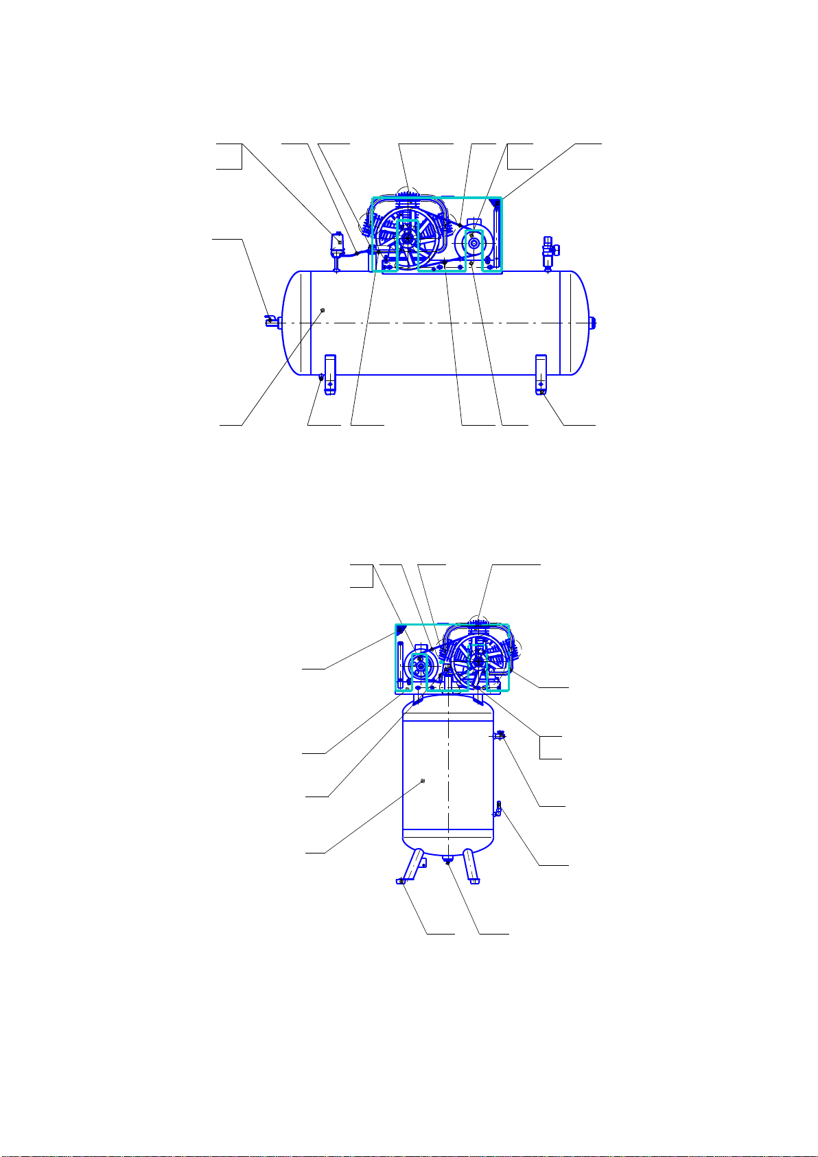
Notes: Complete set of wheels and shock absorbers for the compressor SB4/C-100.LB75 (pos. 15, see
pic. 1), complete set of shock absorbers for compressor SB4/F-270.LB75, SB4/F-500.LB75, SB4/F-
270.LB75V (pos. 15, see pic. 2, 3, 4), as well as the details for their fastening are packed separately.
5. System and the operation principal.
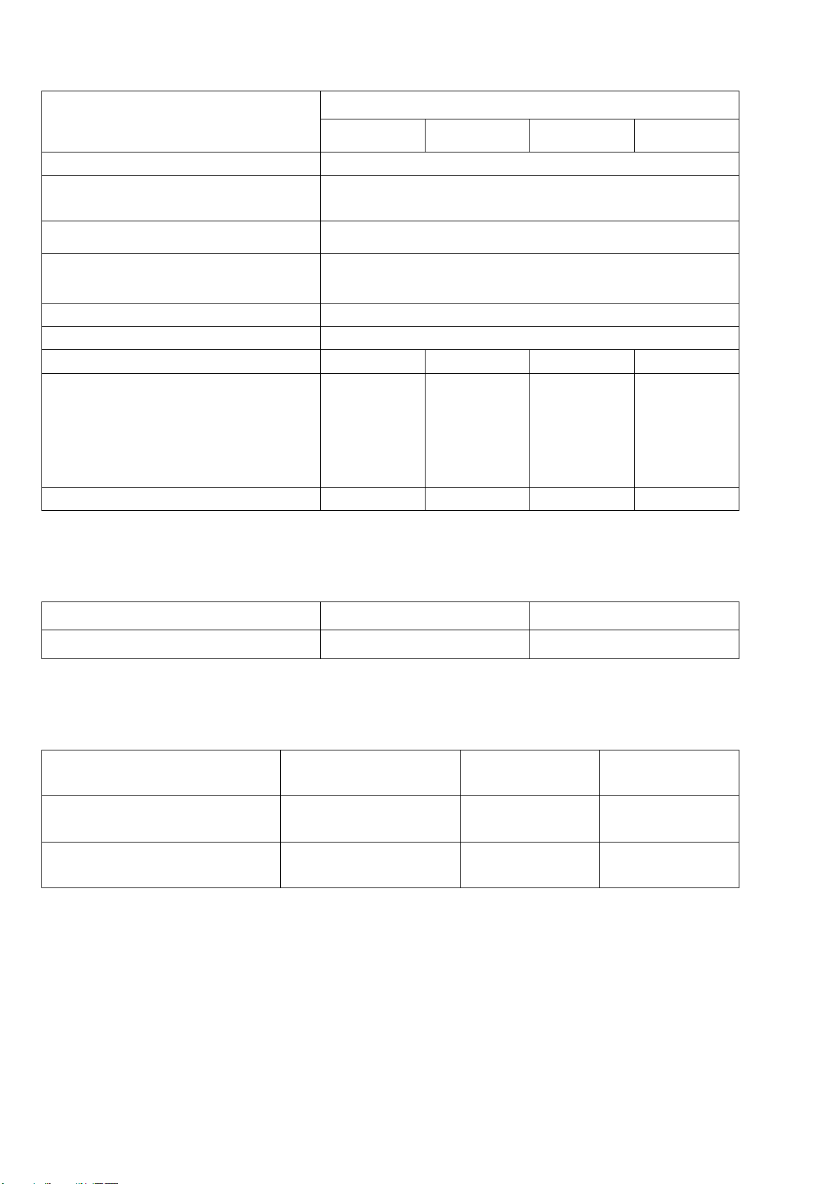
5.1. The compressor (pic. 1) consists of the following main assembly units and compo-
nents: compressor module LB75, receiver 1, bay 2, electric engine 3 with pulley 4, wedge-
type belts 5, protection enclosure 6, pressostate 7, manometer 8, air-outlet unloading pipe 9,
force air pipe 10, discharge cock 11, safety valve 12, check valve 13, overflow valve 14,
wheels and shock absorbers 15.
Compressor module –piston-type, single-stage, double-cylinder with air-cooling –is
made for compressed air production.
Greasing of rubbing surfaces of the compressor module’s components is made by
means of oil spraying. Oil pouring into the crater is accomplished through the carter’s port,
oil drain is accomplished through an aperture in the crater’s bottom, which is blanked with
the cap.
Receiver 1 (see pic. 1, 2, 3, 4) serves for collecting of compressed air, avoidance of
pressure pulsation, condensate and oil segregation. Receiver is also a body, on the base of
which other modules and compressor’s components are mounted.
Receiver has connecting pipes for telepressostate or pressostate 7, check valve 13, over-
flow valve 14, safety valve 12 and holders for mounting of the bay.
Bay 2 is meant for assembling of the compressor’s module, engine, wedge-belt trans-
mission and protection enclosure.
Electric engine 3 is meant for the compressor’s drive.
Telepressostate or pressostate 7 provides the operation of the compressor in automatic
mode and maintains the pressure in the receiver.
Unloading air channel 9 serves for unload of the compressed air out of the force air pipe
10 after the compressor’s shutdown, in order to make its subsequent start easier.
Spigot 11 with the pressure regulator serves for air supply.
Safety valve 12 serves for limiting of the maximum pressure in receiver and is set for
the pressure of the emergency response –(1,05+0,05) MPa.
Check valve 13 ensures the compressed air supply in the direction from the compres-
sor’s module to receiver only.
Discharge cock 14 serves for discharge of condensate from receiver.
Manometer 8 serves for pressure control in receiver.

6
General view of the compressor SB4/C-100.LB75
Рiс. 1
General view of the compressor SB4/F-270.LB75
LB75
1 2
3
4 567
8
9
10
11
12
13
14
15 15
1 2
3
4
5 6
7
8
9
10
11
12
13
14 15
LB75
Рic.2
General view of the compressor SB4/F-500.LB75

7
Pic. 4
Principal electric circuit
General view of the compressor SB4/F-270.LB75В
LB75
1 2
3
4
5 67
8 9
10
11
12
13
14 15
1
2
3
4 5
6
7
8
LB75
9
10
11
12
13
1415
Hz 400
V

8
6. Safety regulations
6.1. For the compressor’s control are allowed only those persons, who were previously
instructed about its system and maintenance regulations, and who were instructed on the
safety and first-aid measures.
6.2. In the process of running the compressor, the operator should use protective glasses
in order to protect eyes against the foreign particles, brought by the flow of air.
6.3. Compressor should be placed on the horizontal floor surface, in a stable position.
6.4. Do not expose the compressor to the influence of precipitation.
6.5. In the room, where the compressor is situated, it is necessary to ensure good venti-
lation (aeration), checking the ambient temperature, which should be between +5 and
+40 ºC.
6.6. The air sucked in by the compressor should not contain any dust, fumes of any
kind, dangerously explosive or flammable gases, solvent or dye spray, toxic smoke of any
type.
6.7. In case the compressor is situated in a room of critical condition (presence of dust
particle of different types) it is necessary to change filters more often. If the filters loose their
carrying capacity significantly, than it can lead to crash of the suction, force or check valve.
6.8. The usage of the compressor is limited to the air compression, that is why it can not
be used with other gases.
6.9. Utilization of compressed air for other stipulated purposes (supercharge, pneumatic
instrument, coloring, washing with the water-base means* etc.) is conditioned by the
knowledge and observance of the standards, provided for each occasion.
6.10. When the compressor is plugged to the connection line, or to the operation unit, it
is recommended to use pneumoapparatus and flexible lines of the same size and having the
same characteristics (pressure and temperature).
Pic. 5
Ì à ñ ñ à Ì à ñ ø ò à á
È ç ì .
Ë è ñ ò
¹ ä î ê ó ì . Ï î ä ï .
Ä à ò à
Ë è ò .
Ð à ç ð à á .
Ï ð î â .
Ò .ê î í ò ð . Ë è ñ ò Ë è ñ ò î â
Í .ê î í ò ð .
Ó ò â .
1:1
È í â . ¹ ï î ä ë . Ï î ä ï . è ä à ò à Â ç à ì . è í â . ¹ È í â . ¹ ä ó á ë . Ï î ä ï . è ä à ò à Ñ ï ð à â . ¹ Ï å ð â . ï ð è ì å í .
Ê î ï è ð î â à ë Ô î ð ì à ò A3
Ð Å À Â Ñ
< Ð Â Ð
3 ~ 50 Hz, 400 V
À , Â , Ñ - energized cable
PE- cable protector
BP - telepressostat
M- elektric motor
M
À N Ð Å
~ 50 Hz, 230 V
XS
< Ð Â Ð
M Ê Ê
Ñ
À , N, - energized cable
PE- cable protector
BP -pressostat
M- elektric motor
C- capacitor (50
µ
F, 450 V)
XS - plug connector
KK - thermal relay 16 A, 250 VAC
Ð Å À Â Ñ
< Ð Â Ð
3 ~ 50 Ã ö , 380 Â
À , Â , Ñ - ï ð î â î ä à ï î ä ê ë þ ÷ å í è ÿ
ï è ò à þ ù å é ñ å ò è
PE-ï ð î â î ä ç à ù è ò û
BP - ò å ë å ï ð å ñ ñ î ñ ò à ò
M- ý ë å ê ò ð î ä â è ã à ò å ë ü
M
À N Ð Å
~ 50 Hz, 230 V
XS
< Ð Â Ð
M Ê Ê
Ñ
À , N, - ï ð î â î ä à ï î ä ê ë þ ÷ å í è ÿ
ï è ò à þ ù å é ñ å ò è
PE- ï ð î â î ä ç à ù è ò û
BP -ï ð å ñ ñ î ñ ò à ò
M- ý ë å ê ò ð î ä â è ã à ò å ë ü
C- ê î í ä å í ñ à ò î ð (50 ì ê Ô , 450 Â )
XS -â è ë ê à ì î ä å ë è 82
KK - ò å ï ë î â î å ð å ë å 16 À , 250 VAC
A, B, C –connection wires of the
power supply source
PE –protection wire
BP –telepressostate
M –electric engine

9
6.11. Compressed air is a flow of energy, and for this reason it is associated with a po-
tential danger. Pipelines, containing the compressed air, should be in working condition and
plugged correspondingly. Before increasing pressure in the flexible lines, one should make
sure, that their rags are well fixed.
6.12. Do not use the flexible lines for the instruments’ shift.
6.13. To move the compressor (switched off) the handle located on the receiver should
be used.
6.14. Before starting the device one should check up the following:
- accuracy of connection to the power supply source and to earth.
-integrity and reliability of the protection enclosure of the wedge-type drive fastening.
-reliability of the compressor’s supports fastening.
- integrity and good order of the safety valves and operating controls.
6.15. For technical testing one should use the present manual, as well as “Regula-
tions on the electric installations” and “Regulations on the safe exploitation of the vessels
under pressure”.
6.16. After completing the rehabilitation the operator should place the protective en-
closure and all other details, by this one should observe the same safety measures, as by the
first start.
6.17. Safety measures by operating of the receiver.
-Properly use the receiver within the limits of pressure and temperature, stated on the
shield with technical data of the manufacturer.
-Constantly control the serviceability and efficacy of the protective and controlling de-
vices (pressostate, safety valve, manometers).
-Do not place receiver in premises with poor ventilation facilities, and in zones, exposed
to heat and flammable materials.
-Do not expose the receiver to vibrations, which can lead to breakage of the welds, be-
cause of the metal’s fatigue strength.
-Every day one should discharge condensate, which is generated in receiver.
When operating the receiver, one should observe the requirements of “Regulations
on the system and safe exploitation of the vessels under pressure”.
6.18. The equivalent of the sound level in the operator’s working zone within 1,0 m
from the compressor, provided the coefficient of usage is 0,6, should not exceed 80 decibel.
6.19. When the noise level exceeds normal level, than it is necessary to use the means
of individual protection.
6.20. The cargo handling procedures should be carried out according to transport marks
on the container.
6.21. Recycling of the used oils and condensates should be carried out with observance
of the appropriate specifications, because these products pollute the environment.
6.22. While operating the compressor one should observe “General fire prevention rules
for the industrial enterprises … ".
It is forbidden:
- To operate the compressor with the faulty or switched - off protection against cur-
rents of short circuit and thermal protection;

10
- To bring in any changes to electrical or pneumatic circuits of the compressor or
their settings. In particular to change the value of the maximal pressure of compressed air
and settings of the safety valve;
-To turn on the compressor with removed protection of wedge-belt transmission;
-While operating the compressor to touch heated details (head and block of cylin-
ders, heat pump, details of the force air-pump, electric motor’s cooling fans);
-To carry out machining or welding of the receiver. In case of defects or corrosion it
is necessary to replace it completely, as it falls under the special norms of safety;
-to touch the compressor with wet hands or to work in wet footwear;
-To direct a jet of compressed air at oneself or other people around;
-To let children and animals into the working area;
-To carry out coloring in a non-aired premises or near open flame;
-To store kerosene, petrol and other inflammable liquids at the site of the com-
pressor’s installation;
-To leave the compressor, which is plugged to the mains, without supervision;
-To carry out repair works of the compressor, which is plugged to the mains,
and when the pressure in the receiver is not releived;
-To transport the compressor, which is under pressure.
7. Pre-starting and operating procedures
7.1. Study the instructions of the present passport attentively and follow them.
7.2. It is important, that the first start of the compressor should be made by the
trained personnel, which carries out various kinds of the control according to the instruc-
tions. 7.3. Accurately open the package, check up completeness, make sure of the absence
of damages.
7.4. Mount wheels and shock-absorbers onto the receiver, mount the compressor on
an even horizontal platform, ensuring in this way an easy approach to the switch and spigot
of air supply to the consumer. For good ventilation and effective cooling it is necessary that
the protections of belt transfer were at a minimum distance of 1 meter from a wall. The
floor of the premises at an installation site of the compressor should be made from a fire-
proof and oil proof material.
7.5. Check up the conformity of the instructions shields on the unit of the compres-
sor, receiver, electric motor and data of the present passport.
7.6. Check up on the oil indicator the level of oil in crank case of the compressor’s
module - it should be within the limits of a red mark on a watching glass. If necessary, add
some oil up to the average level, choose oil according recommendations in the present
instruction. Do not allow outflow of oil from junctures and onto the outside surfaces of the
compressor.
7.7. Check up conformity of the voltage of a power-supply mains with the re-
quirements of the paragraph 2.2 of the present operation manual.
In the case of electrical connection the sequence of phases is of importance, as it
determines the direction of rotation, which should correspond to the direction, speci-
fied by the pointer on a protection enclosure of the wedge-belt transmission.

11
It is necessary to underline, that even the rotation of the engine in the opposite
direction during very short period of time can cause severe damages.
7.8. Reliably connect the compressor to the consumers of compressed air, using the
appropriate pneumoapparatus and pipelines.
7.9. By the first start, and also after the long period of inactivity, it is recommended
to add some drops of compressor oil to the air filter.
7.10. Start-up and stop of the compressor should be carried out only by means of the
switch on pressostate. After starting-up the compressor, while air is used by the consumer,
the relay of pressure of the pressostate automatically switches off and on, maintaining the
pressure of compressed air in the receiver within the given limits - (1,0... 0,8) MPa. At the
first start-up, and also at each repeated switching check the conformity of the direction of
rotation specified on a protective enclosure of wedge-belt transmission and the pulley of
the compressor’s unit.
7.11. The relay of pressure (pressostate) is adjusted by the manufacturer, and should
not be readjusted by the user.
The adjustment of pressure of compressed air at the output is carried out by a regula-
tor of pressure as follows:
- with the spigot being open it is necessary to pull the handle of a regulator of pres-
sure upwards and to rotate it clockwise in order to increase the pressure or counter-
clockwise to reduce pressure;
- After checking the given value of pressure according to manometer, it is necessary
to press the handle, thus having fixed the chosen value;
The amount of processed air depends on pressure in receiver and on its consumption
- at a superfluous consumption the manometer displays low values.
7.12. The compressor is equipped with the device of thermal protection against over-
loads. During long periods of operation and overconsumption of compressed air automatic
switching-off of the compressor due to its overheating is possible.
After the engine cools down to a tolerable temperature, turn off the switch located on
the pressostate’s case, the device of thermal protection is then switched on.
In order to prevent failure of the engine, the intervention in system of thermal protec-
tion is intolerable.
7.13. For correct usage and normal work of the compressor it is necessary to take
into account, that the nominal operation mode is as follows: intermittent with duration
of switched-on periods (SP 60 %) and number of swithched-on periods within one hour
–not more than 60.
7.14. After the complete switching-off let out the air from the receiver.

12
8. Maintenance servicing
For durable and reliable work of the compressor carry out the following operations on
its maintenance servicing:
- After the first 50 working hours check up and if necessary tighten the bolts of cylin-
ders’ heads of the compressor’s unit for indemnification of the temperature shrinkage, the
moment of tightening - 25 Nm;
- check monthly the density of connection of the air pipe-lines, level of oil in the cas-
ing, clear the compressor of a dust and dirt. As a cleaning material one can apply only cot-
ton or linen cloth. The application of the ends and woolen cloths is not allowed;
- change the oil after the first 100 working hours and further through every 500 work-
ing hours. It is not recommended to mix different types of oil. If the oil changes its color
(turns white - presence of water, turns dark - strong overheating) is recommended to re-
place oil immediately;
- Depending on conditions of operation, but no more than once per month, clear the
soaking up air filter, blowing the spout and the filtering element with compressed air. It is
recommended to replace the spout of the air filter or the filtering element at least once a
year, if the compressor works in a clean premises, and even more often if the premises are
dusty. Reduction of the capacity of the air filter reduces service life of the compressor, in-
creases the consumption of the electric power and can result in breakup;
- Merge condensate from the receiver, using the overflow valve, once per week;
- After the first 48 hours of operation and further it is necessary to check periodically
and to adjust the tension of belts and to clear them of dirtying, as at an insufficient tension
belt slips, overheating and decreasing of EFFICIENCY of the compressor’s unit may
occur. When the belts are drawn, there is an excessive loading on bearings, which leads to
their deterioration, overheating of the electric motor and the compressor’s unit. At a correct
tension the deflection of a belt at its middle under the influence of 20 Нshould be within
the limits of (5-6) mm. The tension can be adjusted by means of displacement of the elec-
tric motor, having previously released the bolts, which fasten it to a platform. A pulley of
the electric motor and pulley of unit of the compressor should be at one plane;
- Periodically check the reliability of fastening of the compressor’s unit and engine to
a platform, and of the platform to the receiver;
- Periodically check integrity and reliability of engine controls, control devices, ca-
bles, air channels;
Periodically clear all outside surfaces of the compressor and electric motor for
improvement of the cooling-function.

13
9. Possible malfunctions and the ways of their elimination
The list of possible malfunctions and the ways of their elimination are given in table 5.
Table 5
Name of faultiness
Possible reason
Method of elimination
Compressor’s productivity
slowdown
Distortion of the junctions’
density or air channels
Spot the leak, squeeze the
junctures, change the air
channels.
Air filter loading
Clean the filter element
Belt slip, due to insufficient
tension or fouling
Strain the belt, cleanse it.
Air leak from the pressostate’s
valve –constant “hissing”,
when the compressor is still
stopped.
Air leak because of wearing or
blocking of the check valve.
Unscrew the hexahedral
valve’s head, clean the sad-
dle or the seal disk, or
change them.
Motor overheating and engine
shutdown in the process of op-
eration.
Malfunction of the engine’s
ventilator
Check the ventilator, change
it if necessary.
Insufficient level of oil in the
compressor’s casing
Check the quality and the
level of oil, add some oil, if
necessary.
Continuous compressors opera-
tion with maximal pressure and
air consumption , which trig-
gers heat protection
Bring down the loading, air
consumption and pressure,
restart the compressor.
Compressor’s shutdown in the
process of operation
Feed network distortion
Check the feed network.
The compressor vibrates in the
process of operation, it drones,
after restart the compressor’s
engine doesn’t start, the engine
drones.
No tension in one of the feed
circuit’s phases.
Check and ensure the
feeding of the circuit.
Oil excess in compressed air
and receiver
Oil level in the casing is above
normal
Adjust it to the middle level.
In case of detection of other malfunctions it is necessary to consult the manufacturer.

14
10. Manufacturer’s Warranty
10.1. The manufacturer guarantees conformity of the compressor with the parameters
specified in the present passport, under the condition of observance by the consumer of the
service, storage and transportation regulations.
10.2. Warranty period of operation is 12 months from the date of sale of the compressor
with a mark in the passport, but no more than 18 months from the date of manufacture.
10.3. As far as warranty service, purchasing of replaceable and spare parts are con-
cerned, please consult the dealer of the manufacturer.
10.4. When purchasing the compressor demand accurate and exact filling in of the col-
umns of the unit 12 of the present passport:
- Date of sale;
- The seller’s data;
- Seal of the vendor.
10.5. The buyer loses the right of warranty service in case of:
- loss of the passport;
- completely blank unit 12 of the present passport;
- presence of mechanical and other damages due to infringement of the conditions
of operation, rules of transportation and storage.
11. Transportation and storage
11.1. The transportation of the compressor should be carried out only in the closed
transport. The compressor should be stacked in a packing box.
11.2. The compressor should be stored in closed premises at a temperature from minus
25 up to plus 55 ºСand relative humidity of no more than 80 %.
The content of dust, fumes of acids and alkalis, aggressive gases and other harmful im-
purity in premises, where the compressor is stored, is prohibited.

15
12 Acceptance and packaging certificate
The compressor unit
is completed with a receiver ___________________ l. Serial № ________________,
electric motor ___________________ Serial № ___________________________,
upon shipment the compressor is filled at the enterprise-manufacturer with the oil of the fol-
lowing mark: _________________________________________________________________,
the compressor unit found ready for service.
Packaging was done by _________________________
Manufacture date "_____"__________________ 20 y.
QCD mark ________________________ Seal
REMCOMP
Republic of Belarus, 247672, Rogatschev, ul. Pushkina, b. 62,
Tel: (+375-2339) –39474, 34394, fax (+375-2339) –34320.
Pre-purchase preparation was done:
Date of sale "____"__________ 20 y.
Seller’s requisites _________________________________________
__________________________________________________ Seal

16

17
Warranty Certificate
This certificate is the commitment to carry out guarantee repair of the compressor
The certificate entitles to free-of-charge repair and replacement of details and units failed
due to the fault of the manufacturer during the warranty period.
Dear buyer! Make sure, that all sections of the guarantee coupon are filled in plain and
without corrections.
Item
Model
Factory number
Date of sale
Name and signature of the seller
Seal of the seller
Warranty period is ________________________months from the date of sale.
The article was tested in the following operation
modes__________________________________
in my presence_____________________ (buyer’s signature)
The article was not tested be-
cause:_____________________________________________________________________
____________________________(seal and signature of the seller)
Upon the execution of the act of purchase the general conditions
and requirements of “Regulations on goods’ acceptance accord-
ing to their quality and quantity” should be observed.

18
For warranty repair the following documents should be submitted:
1. Warranty coupon.
2. Documents, confirming the fact of purchase.
3. Passport of the product.
At absence of one of the specified documents manufacturer can refuse to carry out guar-
antee repair.
The warranty service is denied in the following cases:
1. Absence of the completely filled guarantee coupon or its loss;
2. Presence of mechanical and other damages, due to infringement of the requirements to
the conditions of operation, rules of transportation and storage;
3. Spontaneous change of a design or internal system of the device;
4. Infringement of safety of factory guarantee seals on the device and non-authorized ac-
cess to the device’s settings;
5. Application of spare parts and materials which have been not stipulated by the opera-
tional documentation;
6. Infringement of modes of operations established by the operational documentation
(the passport etc.).
The warranty does not cover:
1. Consumed materials, which should be replaced during the warranty period as stipulat-
ed by the rules of maintenance service (filtering elements and materials, oil etc.);
2. Products failed owing to force-majeure events (disaster, acts of nature etc.).
The warranty does not provide for:
1. Preventive maintenance or cleaning of the product or on-site connection, adjustment,
repair or advice by an expert. These works are made under the separate contract.
2. The transport charges are not included into warranty services.
This manual suits for next models
3
Table of contents
Other REMEZA Air Compressor manuals