REMKO CMF User manual

REMKO CMF / CMT
Installation Manual
INVERTER HEAT PUMPS
Edition D – V02/09 2-3


Contents
Carefully read these installation instructions prior to commissioning
using the equipment!
These instructions are part of the unit and must always be stored in
immediate vicinity of the placement location or on the unit.
Subject to modifications; No liability accepted for errors or misprints!
Safety notes 4
Heat pump general 5-9
Installation instructions 10-13
Hydraulic connection 14-15
Electrical connection 15-22
Connection of refrigerant lines 23
Commissioning 24-31
Care and maintenance 32
Troubleshooting 33-35
Unit dimensions 36-37
Characteristic curves 38-40
General terms 41-42
Technical data 43
Made by REMKO
3

REMKO CMF / CMT
Safety notes
These instructions are to be read
through carefully before installing
the device. They contain useful
tips and information, which are
designated by. Warning information
designed to prevent risks to persons
and property are highlighted by
Non-observance of this manual
may endanger persons, the envi-
ronment as well as the equipment
itself and will void any claims for
liability.
■ These instructions must be
stored in the immediate vicinity
of the device.
■ The unit and components may
only be set up and installed by
qualified personnel.
■ The setup, connection and
operation of the unit and its
components must be undertaken
in accordance with the operat-
ing conditions stipulated in this
manual and comply with all ap-
plicable local regulations.
■ It is prohibited to make modi-
fications or changes to equip-
ment or components supplied by
REMKO as this may cause mal-
functions and will lead to loss of
any possible claims for liability.
■ The equipment and components
should not be operated in areas
where there is a heightened risk
of damage. Observe the mini-
mum clearances.
■ The electrical supply should be
adapted to fulfil the require-
ments of the unit.
■ The operational safety of the
equipment and components is
only assured providing they are
used as intended and in a fully
assembled state. Safety devices
may not be modified or deacti-
vated.
■ Operate of equipment or com-
ponents with obvious defects or
signs of damage is prohibited.
■ All housing parts and device
openings, e.g. air inlets and
outlets, may not be blocked by
foreign items, fluids or gases.
■ The equipment and components
must be kept at a safe distance
to inflammable, explosive, com-
bustible, aggressive and dirty
areas or atmospheres.
■ Contact with equipment parts or
components can lead to burns or
injury.
■ Installation, repair and mainte-
nance work should only be car-
ried out by authorised specialists.
Inspection and cleaning can be
performed by the operator pro-
viding the equipment is not live.
■ Appropriate hazard prevention
measures are to be taken when
performing installation, repair or
maintenance, or cleaning work
on the equipment.
■ The room must be properly
ventilated before re-starting the
equipment in the event that
refrigerant leaks out from the
indoor unit. Otherwise there is
danger of suffocation.
■ Tripped circuit breakers may only
be replaced by similarly con-
structed models.
■ The units must be inspected by
a service technician at least once
annually.
■ In case of defects that endanger
the operational safety of the
unit, operation must be discon-
tinued.
■ The units may only be installed
at the points provided for this
purpose on site.
■ The devices may only be at-
tached to load-bearing struc-
tures or walls.
■ Regulations such as the regional
building regulations and the
Water Ecology Act must be
maintained.
4

Economical and environmen-
tally-conscious heating
The burning of fossil-based energy
sources in order to generate power
creates severe consequences for the
environment. A high percentage of
fossil fuels is also problematic due
to the limited resources of oil and
gas and the price increases result-
ing from this. For this reason, many
people today are thinking both
economically and environmentally-
consciously in terms of heating.
The application of heat pump
technology enables both of these
concepts to be combined. It makes
use of the energy which is perma-
nently available in the air, water
and soil and converts it into usable
heating energy by means of input-
ting electrical energy.
Heat pump general
Arguments for REMKO
■ Low heating costs in comparison
to oil and gas
■ Heat pumps represent a contri-
bution to environmental protec-
tion
■ Lower CO2emissions in com-
parison to oil and gas heating
■ Numerous models are able to
cool as well as heat
■ Low noise level of the outdoor
unit
■ Flexible erection due to split
system design
■ Negligible maintenance costs
Heat sources
There are essentially three heat
sources that heat pumps can derive
energy from. These are air, soil and
groundwater. The air heat pumps
have the advantage that the air
source is available everywhere are
in unlimited amounts an that it can
be utilised free-of-charge. A disad-
vantage is that the outside air is at
its coldest when the heat require-
ment is greatest. Brine heat pumps
extract energy from the soil.
However, in order to generate a
heat content of 4kW, it is only
necessary to input approximately
1kW of electricity. The rest is made
available free-of-charge by the
environment.
This is undertaken in serpentine
pipe networks which are laid ap-
prox. 1m deep or placed by means
of drilling. The disadvantage is the
large space requirements for the
serpentine pipe networks or the
high cost of drilling. A permanent
cooling of the soil is also possible.
Water heat pumps require two
wells in order to obtain heat from
the groundwater, one supply well
and one dry well. The development
of this source is not possible every-
where, it is expensive and requires
planning permission.
5

REMKO CMF / CMT
A heat pump is a device which
makes use of a working medium
to absorb ambient heat under low
temperatures and transports this
heat to a place where it can be
of use for heating purposes. Heat
pumps work according to the same
principles as a refrigerator. The dif-
ference is that the "waste product"
of the refrigerator, the heat, is the
goal in this case.
The main components of the
refrigeration circuit consist of an
evaporator, compressor, liquefier
and expansion valve.
Finned evaporators serve to evapo-
rate the refrigerant at low pressure
even at low heat source tem-
peratures, thereby absorbing the
ambient energy. In the compres-
sor, the refrigerant is compressed
to a higher pressure by means of
applying electrical energy, thereby
increasing it up the correct tem-
perature level.Afterwards the hot
refrigerant gas reaches the liquefier,
a plate heat exchanger.
Here the hot gas condenses and
releases its heat to the heating
system.The liquefied refrigerant is
Heat pump modes
Heat pumps can work in various
operating modes.
Monovalent The heat pump is the
sole heating appliance in the build-
ing all year round.This mode is par-
ticularly suitable for heating plants
with low supply water temperatures
and is primarily used in combina-
tion with brine/water and water/
water heat pumps.
Single energy sourceThe heating
system does not require a second-
ary heating boiler. The heat pump
covers a large proportion of the re-
quired heating power. Occasionally,
when it is extremely cold outside,
an electrical booster heating system
switches on in order to support the
heat pump as required.
Bivalent parallel modeThe heat
pump provides the entire heating
energy down to a predetermined
outdoor temperature. If the out-
door temperature falls below this
value, a secondary heating appli-
ance switches on in order to sup-
port the heat pump.
This may take the form of alterna-
tive operation with oil or gas-fired
heating or regenerative operation
utilising solar energy or wood fuel
heating.
This mode is possible for all heating
systems.
then decompressed and cooled in a
flow regulator, the expansion valve.
Subsequently, the refrigerant flows
back into the evaporator and the
circuit is completed.
A heat pump manager is used in or-
der to control the process, which in
addition to all safety functions also
provides fully automatic operation.
The water circuit for the CMF Series
indoor units includes a circulation
pump, a plate heat exchanger,
dirt trap, safety valve, manometer,
filling and drain valve, automatic
deaerator and flow monitor.The
CMT Series is additionally equipped
with a diaphragm expansion vessel,
a three-way switching valve and a
storage tank.
Wall and floor-mounted units, con-
densation pans, condensate trough
heating, 3-way switching valves,
overflow valves and additional
sensors are available as accessories.
Evaporation Liquefaction
Condensing
Decompression
Functional diagram heating
inverter heat pump
Heat pump outdoor unit
Outdoor area
Heat pump indoor unit
Indoor area
6

Layout
Building type Specific heating
output in W/m2
Passive energy house
approx. 10
Low-energy house built in 2002
approx. 40
according to energy conservation order regarding heat
insulation 1995
approx. 60
Modern building constructed around 1984
approx. 80
Partially renovated old building constructed pre-1977
approx. 100
Non-renovated old building constructed pre-1977
approx. 200
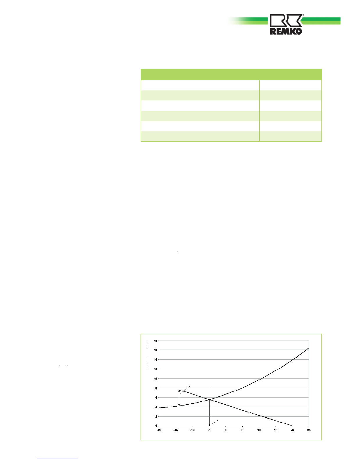
The diagram with the heating ca-
pacity characteristics shows a sim-
plified linear heating requirement.
A connecting line is drawn from the
desired room temperature (20°C)
and the point where the average
low outdoor temperature (local low
for the year) and the heat require-
ment meets (in this case: -14°C and
7.4kW). The intersection of the two
curves are plotted on the X axis
and the temperature of the balance
point is read off. In this case it is
-5°C.
The size of the submersion tube
heater is the difference between
the maximum heat requirement on
the coldest days of the year and the
heating output on these days. In
the example, the required output is
7.4kW – 4.7kW = 2.7kW.
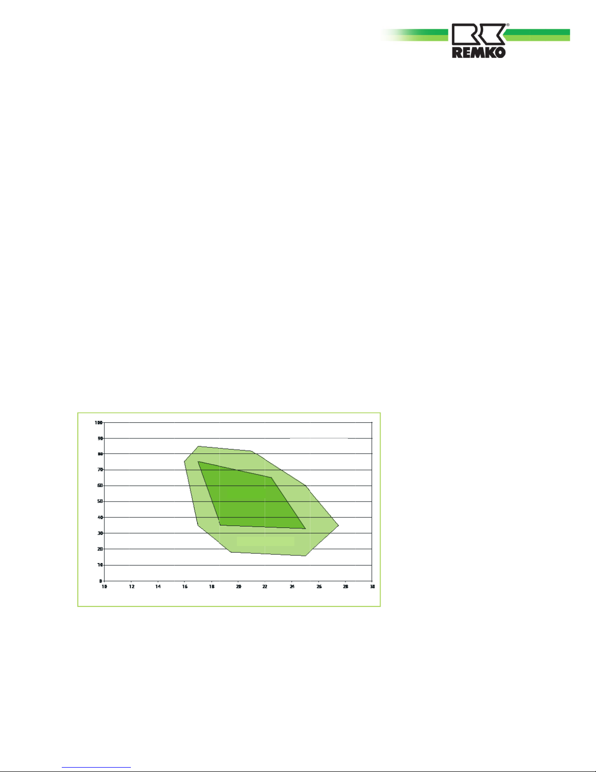
A residential home comprised of
160m² living-space and a heat
requirement of 40 W/m² has been
selected for the example design.
A total of five persons live in the
house. The heating load amounts
to 160m240W/m2=6,400W. Add-
ing a drinking water allowance of
1 kW results in a required heating
power of 7.4kW.
The dimensioning of the heat pump
is given graphically on the diagram
below together with the outdoor-
temperature-dependent building heat
requirements and the heating capacity
characteristics for the heat pump.
A precise calculation of the build-
ing's heating load according to EN
12831 is required for the design
and dimensioning of a heating
system.
However, approximate require-
ments can be determined based
on the year of construction and
the type of building. The adjacent
table shows the approximate spe-
cific heating loads for a number of
building types. The required heat-
ing system output can be calcu-
lated by multiplying the area to be
heated with the given values.
Various factors have to be consid-
ered in order to achieve a precise
calculation.The transmission heat
requirement, the infiltration heat
loss and an allowance for water
heating comprise the total heating
output which has to be provided by
the heating system.
The total area of the floor surfaces,
exterior wall windows, doors and
roofing is required in order to
determine the transmission heat
requirement. In addition, informa-
tion about the materials used in the
building is required, as these lead
to extremely varied thermal trans-
mission coefficients (the so called
K value). Also required is the room
temperature and the average low,
the lowest average outdoor tem-
perature of the year.
The formula for determining the
transmission heat requirement
isQ=A U (tR-TA) and this must be
calculated individually for the areas
surrounding all rooms.
The infiltration heat requirement
takes into consideration how often
the heated room air is exchanged
for cold external air. The room vol-
ume V, the air exchange frequency
n and the specific heat capacity of
the air is also required in addition to
the room temperature and average
low temperature. The formula for
this is Q=V n c (tR-tA).
An approximate allowance for wa-
ter heating per person amounts to
0.2 kW according to VDI 2067.
Temperature in °C
Bivalence point
Necessary additional
power
Heating capacity in kW
7

REMKO CMF / CMT
Characteristics of REMKO inverter heat pumps
Heat source outdoor air
An air/water heat pump absorbs
energy from the outdoor air as its
heat source and transmits this to
the heating system.They have the
following advantages over a brine/
water and water/water heat pump
system:
Split AC unit
The REMKO
inverter heat pump is
a so called split AC unit. This means
that is consists of an outdoor unit
and an indoor unit, both of which
are connected via refrigerant-carry-
ing copper pipes. This means that
there are no water-carrying pipes
laid from the indoors to outdoors
which need to be made frost proof.
The outdoor unit contains only the
condenser, the evaporator and the
expansion valve. This means that
the outdoor unit is considerably
smaller.
The indoor module contains the
liquefier for the circuit and the con-
nections for the heating network.
The heat pump's condenser is
equipped with a requirement-de-
pendent speed control system. The
power control on conventional heat
pumps provides only two states,
either on (full power) or off (no
power). The heat pump switches
on when the temperature drops
below a certain level and switches
off again when this temperature
has been reached.
This type of power control is
extremely inefficient.The power
control on REMKO'S
inverter heat
pumps is continuously modified to
the actual heat requirement.
The electronics system has an
integrated frequency converter
which serves to modify the con-
denser speed and the speed of the
evaporator fan as required. The
condenser works at a higher speed
when under full load as when it
is under partial load. The lower
speeds ensure a longer operational
lifetime for the components, im-
proved coefficient of performance
and lower noise.
Lower speeds also result in lower
energy consumption (electricity).
■ Can be used everywhereAir is
available everywhere in unlim-
ited quantities. For example, no
wells are required.
■ No excavation work requiredNo
large areas are required for soil
collectors.
■ EconomicalExpensive drilling is
not required.
■ Excellent value for money and
simple installation
■ Particularly suitable for low-
energy houses with low inlet
temperatures
■ Ideal for bivalent operation, in
order to save energy
8
Minimal temperature deviations
means savings in energy
Time T
Temperature °C
1/3 The inverter requires 1/3 of the time of
conventional systems to start up
Conventional
Inverter

Defrost by circulation reversal
At temperatures under approx. 5°C
atmospheric moisture freezes on
the evaporator which can lead to
the formation of an ice layer. This
can cause the heat transfer from
the air to the refrigerant and the air
flow to be reduced.
In this case, the ice must be removed.
A four-way valve serves to reverse
the refrigerant circuit, so that the
hot gas from the compressor flows
through the original evaporator and
the ice that has formed there can
melt.
The defrost process is not initiated
after a predetermined time, rather it
is carried out as required in order to
save energy.
Cooling mode with models
CMF 90, CMF 150, CMT 100
and CMT 150
Due to the circulation reversal sys-
tem, a number of REMKO inverter
heat pump models also offer cool-
ing operation.
Cooling mode utilises the refriger-
ant components in order to produce
cold water, in order that heat can
be removed from the building.
This can either take the form of
dynamic cooling or passive cooling.
Under dynamic cooling the re-
frigerating capacity is actively
transferred to the indoor air. This
is undertaken by means of water-
based fan convectors. In doing so,
it is desirable that the inlet temper-
atures are under the dewpoint, in
order to transfer a higher refrigerat-
ing capacity and to dehumidify the
indoor air.
Passive cooling refers to the ab-
sorption of heat via cooled floors,
walls or ceiling surfaces. In doing
so, water-carrying pipes make the
structural sections into thermi-
cally effective heat exchangers. In
order to achieve this, the refriger-
ant temperature has to lie above
the dewpoint, in order to avoid the
formation of condensation. Dew-
point monitoring is required for this
purpose.
We recommend dynamic cooling
with fan convectors, in order to
achieve increased thermal perform-
ance and in order to dehumidify the
air on muggy summer days. The
advantage here is that dewpoint
monitoring is not required.
Versions
We offer two different indoor unit
designs.
The wall-mounted CMF Series is
equipped with a circulation pump
and a safety module on the up-
stream face. In addition, an electri-
cal heating coil can be integrated.
The CMT Series of indoor modules
is additionally equipped with a stor-
age tank and an expansion vessel.
The storage tank has a capacity of
150 litres.
We recommend an external storage
tank for the CMF Series in order to
avoid short operating times for the
heat pump and in order to ensure
that sufficient energy is available to
bridge off-periods.
The comfort zone shows which values for temperature and humidity
are considered comfortable for people. This range should ideally be met
when heating or air-conditioning buildings.
Relative air humidity in %
Uneasily humid
Uneasily dry
Still comfy
Comfy
Room air temperature in °C
9

REMKO CMF / CMT
Installation instructions
The indoor and outdoor modules
have to be connected with refrigerant
lines of dimensions 3/8" and 5/8".
System design
Outdoor unit
Indoor
module CMT
Series
fan
Outdoor area
Refrigerant lines 3/8" and 5/8"
Mains cable
Interior 3x
Draining pan
Indoor area
Condensate drain
(must be designed to be frost proof!)
* Mains supply
3x230V/1~/50Hz 25A
electrical connection
4x
Domestic water 1"
Hot water 1"
Outdoor unit
fan
Condensate drain
(must be designed to be frost proof!)
electrical connection
4x
Indoor module
CMF Series
Mains cable
Interior 3x
Condensation line
Hot water 1"
A four-wire control cable has to be
laid between the two modules.
Both the indoor and outdoor
modules require a separate power
supply.
* Mains supply
3x230V/1~/50Hz 25A
Refrigerant lines 3/8" and 5/8"
* Mains power supply 5x for outdoor modules CMF 140, CMF 150 and CMT 150: 400V/3~N/50Hz 16A
optional mains
power line
Electric heating
230V or 400V
Mains cable
Electric heating
230V or 400V
Domestic water 1"
10

■
These instructions are to be
observed when installing the
entire system.
■
The device should be delivered
as near as possible to the site of
installation in its original pack-
aging in order to avoid trans-
port damage.
■
The device is to be checked for
visible signs of transport dam-
age.
Possible faults are to be report-
ed immediately to the contrac-
tualpartner and the haulage
company.
■
Suitable sites for installation are
to be selected.
■
The stops valves for the refrig-
erant lines may only be opened
immediately before commis-
sioning of the system.
General Information
All electrical installation work
should be performed by spe-
cialist contractors.
CAUTION
The installation of refrigerant
plants may only be undertaken
by trained specialist personnel.
CAUTION
Open refrigerant pipes must
be protected against the intro-
duction of moisture by means
of suitable caps or adhesive
strips Refrigerant pipes may
not be kinked or depressed.
CAUTION
■
Special precautions relating to
the oil return are to be met
if the outdoor component is
located above the indoor unit
(please refer to the "Connec-
tion of Refrigerant Lines" sec-
tion).
■
Add refrigerant if the basic
length of the refrigerant pipe
exceeds 30 meters.
■
Establish all electrical connec-
tions in accordance with the rel-
evant DIN and VDE standards.
■
The electrical power cables
must be fastened in a proper
manner with electrical termi-
nals.Otherwise there is a risk of
fire.
Wall breakthroughs
■
A wall breakthrough of at least
70 mm diameter and 10 mm
slope from the inside to the
outside must be created.
■
The interior of the break-
through is to be padded, e.g.
with a cladding PVC pipe in
order to avoid damage (see
figure).
■
After installation has been
completed, use a suitable
sealing compound to close off
the wall breakthrough under
observation of fire protection
regulations (responsibility of
customer).
Control line
Hot gas line
Liquid line
Supply
11

REMKO CMF / CMT
■
The wall bracket is to be
fastened to the wall with the
supplied fastening materials and
the indoor module hooked on.
■
The wall must possess sufficient
load-bearing capacity for the
weight of the indoor module.
■
Ensure that the wall bracket is
installed level.
■
The indoor module can be
aligned precisely by means of
the adjustment screws on the
rear side of the housing.
■
The indoor module is to be
mounted in such a way that
all of the sides have sufficient
space for purposes of instal-
lation and maintenance.It is
equally important that there
is sufficient space above the
device for installing the safety
module.
Only fixing materials which
are suitable for the given ap-
plication may be used.
NOTE
Installation of the indoor unit
Indoor module CMF Series Indoor module CMT Series
■
The indoor module must be
installed on a firm, level surface.
■
The surface must possess suf-
ficient load-bearing capacity
for the weight of the indoor
module.
■
The height-adjustable feet can
be used to precisely align the
indoor module.
■
The indoor module is to be
mounted in such a way that
all of the sides have sufficient
space for purposes of instal-
lation and maintenance.It is
equally important that there is
also sufficient space above the
device for installing the pipes
and safety module.
12

Pre-cut recesses
■
The device may only be at-
tached to a load-bearing con-
struction or wall.
■
Install the device on floor con-
soles with vibration dampers to
minimise noise.
■
The specified minimum clear-
ances should be maintained
when carrying out the instal-
lation. These protective zones
serve to ensure unrestricted
air inlet and outlet. It must be
ensured that there is sufficient
space available for installation,
maintenance and repairs.
■
The site of installation should
be well ventilated.
Installation of the outdoor module
Wind
20 cm
Snow
CMF 80 / CMF 90 / CMT 100 CMF 140 / CMF 150 / CMT 150
A min. 50 mm min. 50 mm
B min. 750 mm min. 1,000 mm
C min. 150 mm min. 150 mm
D min. 250 mm min. 500 mm
E min. 100 mm min. 100 mm
■
If the outdoor module is
erected in an area where there
is strong wind, then the device
must be protected from the
wind. The snow line is to be ob-
served during installation (see
figures).
■
It is to be ensured that the
outdoor module is only installed
vertically.
■
The outdoor module is at-
tached by means of 4 screws
with vibration dampers on floor
consoles.
Vibration dampers must also
be used when installing the
equipment with a wall bracket.
The vibration dampers serve to
reduce the noise transmittance.
■
The Water Ecology Act is to be
observed.
A number of sides must have
greater clearance that the mini-
mum specified clearance.
CAUTION
■
A heatable condensate catch
pan ensures that condensation
from the pan is able to drain
off.It must be ensured that the
condensation water is frost-pro-
tected in order that it can drain
off (gravel, drainage).
The right-hand side wall of the
device is to be removed before
installing the electrical cables and
the refrigerant line to the outdoor
module. In order to do so, release
the three screws on the side wall
and pull the panel downwards. If
there is insufficient room under-
neath the device for the refrigerant
lines, then the precut recesses can
be removed from the lower enclo-
sure panel and the pipes can be
guided in through these openings.
Air intake
Air outlet
13

REMKO CMF / CMT
Safety valve
Automatic deaerator
Manometer
Indoor unit
Hydraulic connection
Turning the thermometer
heads serves to close or open
the stop valves!
CAUTION
■
For models CMF 80, CMF 90
and CMT 100 it must be en-
sured that the condenser pump
flow rate always amounts to
1
,
400
l/h
. For models CMF 140,
CMF 150 and CMT 150 the
flow rate must amount to 2,200
l/h. The indoor module com-
ponents are designed for these
flow rates.
■
A hydraulic splitter or storage
tank is to be used in order to
separate the system circuits.
■
A pipeline network connection
must be undertaken before
installing the heat pump.
■
Floor heating systems must be
protected against excessively
high and low inlet tempera-
tures.
■
The pipe diameters for the
supply and return connections
of the heat pump may not be
reduced before the connection
of a system separation.
■
Air bleed valves and drain-off
taps must be planned for in
suitable areas.
■
The complete pipe network for
the system must be flushed be-
fore connecting the heat pump.
■
The safety module contained in
the scope of delivery comprises
of a manometer, air vent and
safety valve. It is to be mounted
on the pipe connection for the
indoor module.
■
An expansion vessel must be
designed for the entire hy-
draulic system. The expansion
vessel for the CMT range has a
volume of 12 litres and is only
intended to protect the stor-
age tank and not for the entire
pipe network of the hydraulic
system.
■
The system pressure of the
entire pipe network is to be
matched to the hydraulic sys-
tem and must be checked when
the heat pump is in a non-oper-
ative state.
■
In order to reduce the heating
cycles to a minimum, it must
be ensured that the heating
load from the heat pump is
fully transferred to the heating
system.
■
The supplied stop cocks are
to be positioned directly at
the connections for the heat
pump inlet and return lines.
The
shut-off valves each contain a
thermometer with gauge.
■
The dirt traps should be in-
stalled outside of the heat
pump in the return line.
A separate installation must be
carried out for every system.
NOTE
Manual-
deaerator
Expansion-
vessel
14

■
It is to be ensured that a gate
valve is positioned upstream
and downstream of the dirt
traps. This ensures that the dirt
traps can be checked at any
time without loosing water.
■
The dirt traps must be checked
during every service of the sys-
tem.
■
The indoor module contains a
ventilation connection in the
inlet line in order to enable ad-
ditional venting.
It must be ensured that a
sufficient flow-rate is given.
CAUTION
Manual-
deaerator
■
All visible metallic surfaces must
be additionally insulated.
■
Cooling mode via the heating
circuit requires a completely
vapour diffusion tight insulation
along the entire length of the
pipework.
■
All outgoing heating circuits
including the connections for
water heating are to be secured
against circulating water by
means of flap valves.
■
The system must be flushed
before commissioning the sys-
tem. The entire system must be
subjected to a tightness check
and a thorough venting.
Electrical connection
For the CMF and CMT devices, a
mains cable must be laid for both
the outdoor and indoor modules.
In some cases it may also be pos-
sible to feed the power supply
for the indoor module from the
outdoor module. The outdoor
modules of Series CMF 80, CMF
90, CMT 100 require a 230V
mains supply. The outdoor mod-
ules of Series CMF 140, CMF 150
and CMT 150 have to be provided
with a 400 V supply. The electrical
connection between the modules
is realised with a 4-wire control
cable.
A clockwise rotating field must
be ensured for 400 V power
supplies.
CAUTION
The following diagram provides an
overview of the required connec-
tions.
The diameters for the leads and
the connection cables are to be
selected according to local regula-
tions.
The fusing level is to be taken from
the technical data.
It is possible that the energy sup-
ply company will provide a special
power supply tariff for the opera-
tion of heat pumps.
Individual tariff options should be
agreed with the local energy sup-
ply company.
Check all plugged and clamped
terminals to verify they are
seated correctly and making a
permanent contact. Re-tighten
as required.
CAUTION
15

REMKO CMF / CMT
Connection diagram
Electrical
heater
Sub-distribution by customers
Connection outdoor unit
Connection indoor unit
Power plant clearing contact
Connection electrical heating
* 5-wire (example NYM-I 5x2,5 mm²)
3-wire (example NYM-I 3x4 mm²)
3-wire (example NYM-I 3x1,5 mm²)
* 5-wire (example NYM-I 5x2,5 mm²)
2-wire (example NYM-I 2x1 mm²)
4-wire (example NYM-I 4x1mm²)
Pump heating circuit 1
Pump heating circuit 2
Charge pump / U-valve
Mixer heating circuit 2
Pump cooling
Circulation pump
Reversing valve cooling
(not at CMF 80 and 140)
Clearance 2nd. heater.
The clamp configuration depends on
the model!
Connection Pilot wire
Outdoor unit Indoor unit
Return
Collector
Tank
Intake heating circuit 1
Intake heating circuit 2
Process water
Collector
* The outdoor units of CMF 80, CMF 90 and CMT 100 have to be supplied by a 3-wire power cable!
The outdoor units of CMF 140, CMF 150 and CMT 250 have to be supplied by a 5-wire power cable!
The cross section indicated have to be complied with the pipe length and kind of construction in order to the VDE
0900 and technical data!
Outdoor temperature
16

Mains cable
Control line
Electrical connection of the outdoor
module
■
The side wall of the the unit
is to be removed by means of
loosening the screws in order to
connect the mains supply (see
"Installation of the Outdoor
Module").
■
Details concerning the electri-
cal protection of the system are
given in the technical data.
The required diameters are to
be observed!
■
The supply cable must be con-
nected under consideration of
the correct polarity.
■
The electrical connection dia-
gram is to be observed.
■
The four-wire control cable is to
be connected to terminals S1,
S2, S3 and the earth terminal.
■
The correct polarity must be
ensured when connecting the
connection cables.
■
If the outdoor module is in-
stalled on a roof, then it must
be protected against lightening
strikes.
■
The cables are to be secured
with the cord grips.
Electrical connection of the indoor
module
The following points refer to the
figures shown below. The CMF
Series indoor module is shown in
the example. The connection for
the CMT Series is established cor-
respondingly.
1. The lower housing cover is
folded down and removed.
2. The front of the housing is fixed
in position with two screws and
can be taken out in an upward
direction after the screws are
released.
3. The cover of the switching cabi-
net can be folded down and
removed after the two screws
have been removed.
4. After the screws have been
released, the switching cabinet
can be folded down in order to
facilitate installation.
Ensure correct polarity when
connecting the electrical leads.
CAUTION
5. The cable passages serve to en-
able the supply lines to be fed
in for the indoor unit as well as
the connection cable between
the indoor and outdoor mod-
ules and the leads for the exter-
nal devices and sensors into the
indoor module.
In doing so, it is to be ensured
that the cable passages for the
CMT Series are at the top.
■
The number of lines and the
sensors is dependent on the
configuration of the heating
system and the components.
■
The leads are to be connected
in accordance with the terminal
assignment diagram.
Cable passage
1. 2. 3.
4. 5.
17

REMKO CMF / CMT
Circuit diagram for models CMF 80 and CMF 140
Heat pump -
temperature
Clearance
compressor
Switch board heat pump manager Internal fuse
Flow
control
Outlet
yellow
Condenser
pump
Clearance exter-
nal heater 2
open close
Mixer heating
circuit 2
Charge pump
/ U-valve
Pump
heating
circuit 2
Pump
heating
circuit 1
Power
plant
contact
Contact closed
means clearance
Switch board sensor connector
Switch board outdoor unit
Switch board heat pump manager
Outdoor unit
red
18

If an electricity tariff has been selected without energy
supply company shut-off, then a bridge is to be cre-
ated between terminals X1.5 and X1.6.
If an electricity tariff with energy supply company
shut-off is selected, then the customer is to arrange
for an on-site starter contact for terminals X1.5 and
X1.6. Likewise, the supply line for the outdoor mod-
ule requires an interruption mechanism installed by
the customer in accordance with the energy supply
company's off-periods. In this case it is necessary to
have a separate supply line for the indoor unit! The
booster heating system requires a separate supply line
with fuse protection in the switching cabinet con-
nected to contactor terminal K1.
Terminal assignment diagram for models CMF 80 and CMF 140
Terminal Connection
X1.1 Supply line L
X1.2 Supply line N
X1.3 Supply line PE
X1.4 Live phase L
X1.5 Energy supply company release contact
X1.6 Energy supply company release contact
X1.7 Flow monitor
X1.8 Flow monitor
X1.9 Connection cable PE
X1.10 Connection cable S3
X1.11 Connection cable S2
X1.12 Connection cable S1
X1.13 Pump heating circuit 1 L
X1.14 Pump heating circuit 1 N
X1.15 Pump heating circuit 1 PE
X1.16 Pump heating circuit 2 L
X1.17 Pump heating circuit 2 N
X1.18 Pump heating circuit 2 PE
X1.19 Charging pump / switching valve L
X1.20 Charging pump / switching valve N
X1.21 Charging pump / switching valve PE
X1.22 Mixer heating circuit 2 open
X1.23 Mixer heating circuit 2 N
X1.24 Mixer heating circuit 2 PE
X1.25 Mixer heating circuit 2 close
X1.26
X1.27
X1.28 Release heating appliance 2 com
X1.29 Release heating appliance 2 NC
X1.30 Release heating appliance 2 NO
X1.31 Circulating pump (collector pump) L
X1.32 Circulating pump (collector pump) N
X1.33 Circulating pump (collector pump) PE
X1.34 Condenser pump L
X1.35 Condenser pump N
X1.36 Condenser pump PE
Terminal Connection
X2.1 BUS H
X2.2 BUS +
X2.3 BUS L
X2.4 BUS -
X2.5 0 - 10 V -
X2.6 0 - 10 V +
X2.7 Return sensor / F17
X2.8 Switch input / F15
X2.9 Collector sensor / F 14 (PT 1000)
X2.10 F 13
X2.11 Storage tank sensor lower / F 12
X2.12 Supply sensor heating circuit 1 / F11
X2.13 F 1
X2.14 F 2
X2.15 F 3
X2.16 Supply sensor heating circuit 2 / F5
X2.17 Domestic water sensor / F6
X2.18 Collector sensor / F8
X2.19 External sensor / F9
X2.20 Sensor liquid line
X2.21 Sensor liquid line
X2. Earth contact sensor
19

REMKO CMF / CMT
20
21
24
25
26
27
28
X1.1
X1.13 X1.16 X1.19 X1.22 X1.25
A2
A1 A3 A4 A5
Pumpe Pumpe Ladepumpe/
Mischer HK2
auf zu
N L
HK1 HK2 U.Ventil
Platine Wärmepumpenmanager
gelb
rot
31
30
29
34
33
32
36
35
38
37
11
14
K3
21 24
K3
A2
K3
A2
K4
11 14
K4
A2
K5
A2
A1
K7
A2
K8
A2
K9
A2
K1
X1.7 X1.28 X1.37 X1.40
X1.8
X1.26
X1.41
X1.6
X1.27 H1
H3
A1
K2
B1
15
K2
A6 A7 A8 A9
Flußwächter E.-Heizstab
Brücke
Pumpe Kühlen Kondensator- Freigabe
extern pumpe
A2
A2
22
A1
A1
A1
A1
A1
A1
A1
12
12
18
weiß
K6
X1.4
X1.5
H2
EVU-
Kontakt
A10
39
40
41
X1.31X1.34
A12
U.Ventil MF4
int. Sicherung
Kühlen
Freigabe Heizen/Kühlen
Kompressor
0 - 10V
11 14
K6
11 14
K7
11 14
K8
11 14
K9
1
2
3
4
5
6
7
8
9
10
11
12
13
14
15
16
17
18
19
X1.12
X1.11
X1.9X1.10
TB61.1
TB61.2
TB61.3
TB61.4
TB62.3
TB62.4
TB142.1
TB142.2
TB142.3
TB141.4
TB141.3
TB6.PE
TB6.S1
TB6.S2
R1
X2-1
X2-2
X2-3
X2-4
X2-5
X2-6
X2-7
X2-8
X2-9
X2-10
X2-11
X2-12
X2-13
X2-14
X2-15
X2-16
X2-17
X2-18
X2-19
X2-20
X2-21
F9
F8
F6
F5
F3
F2
F1
F11
F12
F13
F14
F15
F17
eBUS +
eBUS -
CAN H
CAN L
CAN -
Platine Wärmepumpenmanager Platine Außenmodul
12
12
TB142.4
TB6.S3
Außenmodul
12
12
CAN +
Platine Fühleranschlüsse
WE2
Ausgang
C1
X1.2
X1.14 X1.17 X1.20 X1.23 X1.29 X1.38 X1.32
X1.35 X1.42
11 14
K5
12
X2-
*
X2-
X2-
X2-
X2-
X2-
X2-
X2-
X2-
X2-
X2-
X2-
X2-
Flüssigkeitstemp.-Fühler Sammelstörung
Lufttemp.-Fühler (2,6 kOhm)
5min
Störung
Kompressor
Pumpennachlauf
E-Heizung
Freigabe
Kompressor
Pumpe
Kühlen
Umschaltung
Kühlen/Heizen
EVU
Abschaltung
Freigabe
Wärmeerzeuger
Freigabe 2.
Wärmeerzeuger
Circuit diagram for models CMF 90, CMT 100, CMF150 and CMT 150
Switch board outdoor unit
Switch board sensor connector Outdoor unit
Outlet
Clearance
heater 2
U-Valve
cooling
Condenser
pump
Bridge
electrical
heater
Pump external
cooling
Flow control
Power
plant
contact
Heat pump -
temperature
Clearance
compressor
Heating /
cooling
switch board heat pump manager
Switch board heat pump manager
internal fuse
open close
Mixer heating
circuit 2
Charge pump
/ U-valve
Pump
heating
circuit 1
Pump
heating
circuit 2
yellow
red
white
20
This manual suits for next models
1
Table of contents
Other REMKO Inverter manuals
Popular Inverter manuals by other brands

WACKER Group
WACKER Group LTC 4 Repair manual

Sincro
Sincro HB4 Use and maintenance manual

Wacker Neuson
Wacker Neuson GV 7000A Operator's manual

Generac Power Systems
Generac Power Systems Guardian 04758-2 Installation and owner's manual

Pyle
Pyle Power Inverter PNVU200 owner's manual

SMA
SMA SUNNY TRIPOWER CORE1 Quick reference guide