CHNT Power CPS SCA-T Series User manual
CPS SCA-T Series Grid-tied PV Inverter
Version: 1.0
Shanghai Chint Power Systems CO,.LTD
CPS SCA30-36KTL-T/SA
Installation and Operation Manual
Date: 26/09/2019

CPS SCA-T Series Inverter
Contents
Application Model
Intended Audience
Symbol Conventions
1.1 Personnel Safety
1.2 The PV Inverter Protection
1.3 Installation Safety
1.4 Electrical Connections
1.5 Operating and Commissioning
1.6 Maintenance
1.7 Additional Information
2.1 Functional Models
2.2 Network Application
2.3 Outline and Dimensions
2.4 Working Modes
2.1.1 Function
2.1.2 Model Description
2.3.1 Outline
2.2.1 Grid-tied PV Power Systems
4.1 Checking the Outer Packing
4.2 Moving the Inverter
4.3 Identifying the PV Inverter
4.3.1 Nameplate
3. Storage
01
01
02
03
03
03
04
04
04
05
06
06
06
06
06
07
07
09
12
12
11
12
10
Forward
1 Safety Precautions
2 Overview of the Inverter
3 Storage
4 Installation
4.3.2 Compliance and Safety Symbols 13
13
16
4.4.1 Determining the Installation Position
4.4.2 Installation Mode Requirements
4.4 Installation Requirements 13

CPS SCA-T Series Inverter
5.1 Connecting Protection Ground (PGND) Cables
5.2 Connecting AC Output Cables
5.3 Connecting the PV Strings
5.4 Connecting Communication Cables
5.5 Installation Verification
5.1.1 Preparation
5.1.2 Wiring Procedures
5.4.1 Communication Mode Description
5.3.1 Preparation
5.2.1 Preparation
5.2.2 Procedure of Connecting AC Cables
6.1 Powering ON the Inverter
6.2 Powering OFF the Inverter
7.1 LED Indicator
10 Disposal of the Inverter
11 Technical Specifications
8.1 Routine Maintenance
8.2 The Inverter Troubleshooting
8.3 Removing the Inverter
9.1 Quality Terms
9.2 Liability Waiver
4.5 Support-mounting the Inverter
18
18
19
20
20
21
22
23
27
27
31
32
32
33
43
44
38
39
41
42
42
16
5 Electrical Connections
6 System Operation
7 User Interface
8 Maintenance
9 Quality Guarantee
10 Disposal of the Inverter
11 Technical Specifications
7.2 App ChintHome 36
5.4.2 Connecting RS485 Communication Cables 29
5.4. 3 Setting RS485 Communication Address 30
5.3.2 Procedures of Connecting the PV Strings 25

1
This document is intended for photovoltaic (PV) inverter operating personnel and qualified
electrical technicians.
CPS SCA30KTL-T/SA
CPS SCA-T Series Inverter
Forward
Dear User,
Thank you so much for your choosing 30K-36K, the latest generation of grid-tied PV Strings
inverter (hereinafter referred to as the inverter) designed and developed by CHINT.
This user manual introduces the inverter in terms of its installation, electrical connections,
operation, commissioning, maintenance, and troubleshooting. Please read through the manual
carefully before installing and using the inverter, and keep the manual well for future reference.
Application Model
Grid-tied PV string inverter
Intended Audience
This user manual is subject to change (specific please in kind prevail) without prior notice.
The latest version of user manual and other more information about the product are
available from http://www.chintpower.com/en, and/or by consulting your dealer.
Notes:
CPS SCA36KTL-T/SA
2
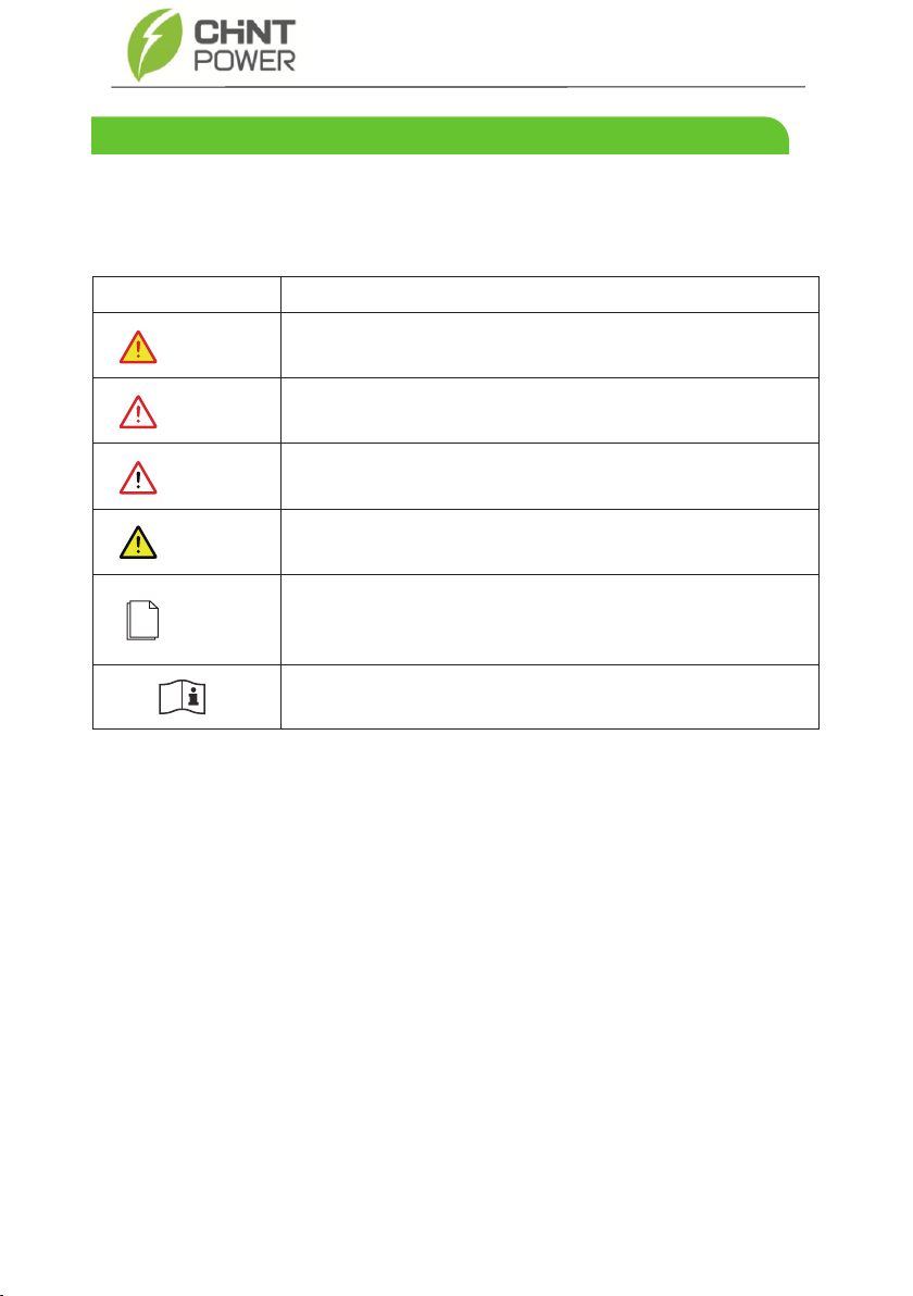
Indicates an imminently hazardous situation which, if not correctly
followed, will result in serious injury or death.
Indicates a potentially hazardous situation which, if not correctly
followed, could result in serious injury or death.
Indicates a potentially hazardous situation which, if not correctly
followed, could result in moderate or minor injury.
Indicates a potentially hazardous situation which, if not correctly
followed, could result in equipment failure, or property damage.
Calls attention to important information, best practices and tips:
supplement safety instructions for your better use of the
inverter to reduce the waste of resource.
Mark on the nameplate. Reminds operators to refer to the
documentation shipped with the inverter.
The following symbols will be frequently used in this User Manual as well as in the process of
actual application.
Symbol Description
WARNING
CAUTION
DANGER
NOTICE
NOTE
CPS SCA-T Series Inverter
Symbol Conventions

3
CPS SCA-T Series Inverter
1 Safety Precautions
a. The PV inverter must be installed, electronically connected, operated and maintained through
specially trained technician;
b. The qualified technician must be familiar with the safety regulations of electrical system,
working process of PV power generation system, and standards of local power grid;
c. The technician must read through this User Manual carefully and master it before any operation.
a. Do not tamper with any warning signs on the inverter enclosure because these signs contain
important information about safe operation.
b. Do not remove or damage the nameplate on the inverter’s enclosure because it contains
important product information.
c. Do not remove the anti-dismantle label on the inverter’s enclosure because it is the basis for
product warranty.
a. Ensure there is no electronical connections around ports of the PV inverter before installing;
b. Adequate ventilation must be provided for inverter installation location. Mount the inverter in
vertical direction, and ensure that no object is put on the heat sink affecting the cooling. (For
details, refer to 4 Installation).
As soon as receiving the PV inverter, please check if it is damaged
during its transportation. If yes, please contact your dealer immediately.
Please read the User Manual carefully before installing the PV inverter;
warranty or liability will be void from CHINT if damage is caused by
installation faults.
NOTICE
NOTICE
1.1 Personnel Safety
1.2 The PV Inverter Protection
1.3 Installation Safety
Before beginning your journey, please read these safety precautions in User Manual carefully.

4
CPS SCA-T Series Inverter
a. Input terminals of the PV inverter apply only to input terminals of PV String; do not connect
any other DC source to the input terminals.
b. Before connecting PV modules, ensure that is its voltage is within the safe range; when
exposed to any sunlight, PV modules can generate high voltage.
c. All electrical connections must meet the electrical standards of the country or region.
d. Cables used in electrical connections must be well fixed, good insulation, and with
appropriate specification.
a. Before getting the permission of electrical power sector in the country / region, the grid-tied
PV inverter cannot start generate power.
b. Follow the procedures of commissioning described in the user manual when commissioning
the PV inverter.
c. Do not touch any other parts'surface except the DC switch when the PV inverter is operating;
its partial parts will be extremely hot and can cause burns.
Before installing the inverter, check all electrical ports to ensure no
damage and no short circuit. Otherwise personal casualty and/or fire
will occur.
While the inverter operating, high voltage can lead to an electrical
shock hazard, and even cause personal casualties. Therefore,
operate the PV inverter strictly according to the safety precautions in
the user manual.
Power OFF all electrical terminals before the inverter maintenance;
strictly comply with the safety precautions in this document when
operating the inverter.
DANGER
DANGER
DANGER
1.4 Electrical Connections
1.5 Operating and Commissioning
1.6 Maintenance
5
CPS SCA-T Series Inverter
a. For personal safety, maintenance personnel must wear appropriate personal protective
equipment (like insulation gloves and protective shoes) for the inverter maintenance.
b. Place temporary warning signs or erect fences to prevent unauthorized access to the
maintenance site.
c. Follow the procedures of maintenance stipulated in the manual strictly.
d. Check the relevant safety and performance of the inverter; rectify any faults that may
compromise the inverter security performance before restarting the inverter.
To avoid any other unforeseeable risk, contact immediately, if CHINT
there is any issue found during operation.
NOTICE
1.7 Additional Information
6
CPS SCA-T Series Inverter
This chapter introduces the inverter and describes its functions, models, network application,
appearance, dimensions, and working process etc.
This series of products is a transformerless grid-tied PV inverter which converts the direct current
of the PV strings to grid-compliant three-phase current and feeds it into utility grid.
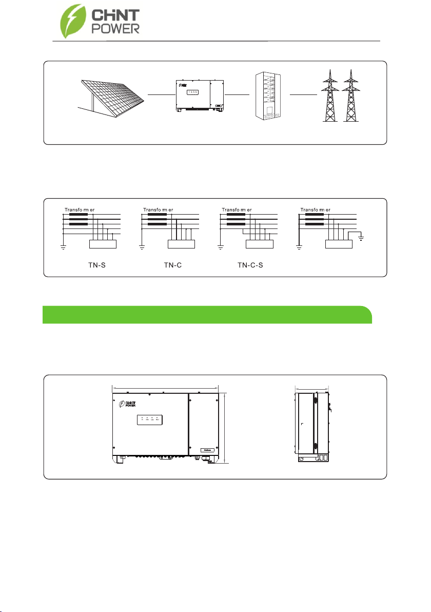
This series of products applies to grid-tied PV power systems for industrial/commercial rooftops,
fishing/farmers light complementary power generation systems, and large ground-based power
stations. Generally, this series inverters is used to low-voltage on-grid PV power system,
as shown in Figure 2.2.
The inverter is transformerless. Add an isolation transformer before
grounding the positive/negative terminal of PV modules (such as
thin film module).
Do not connect PV modules in parallel to mutiple PV inverters.
WARNING
WARNING
2 Overview of the Inverter
2.1.1 Function
2.1.2 Model Description
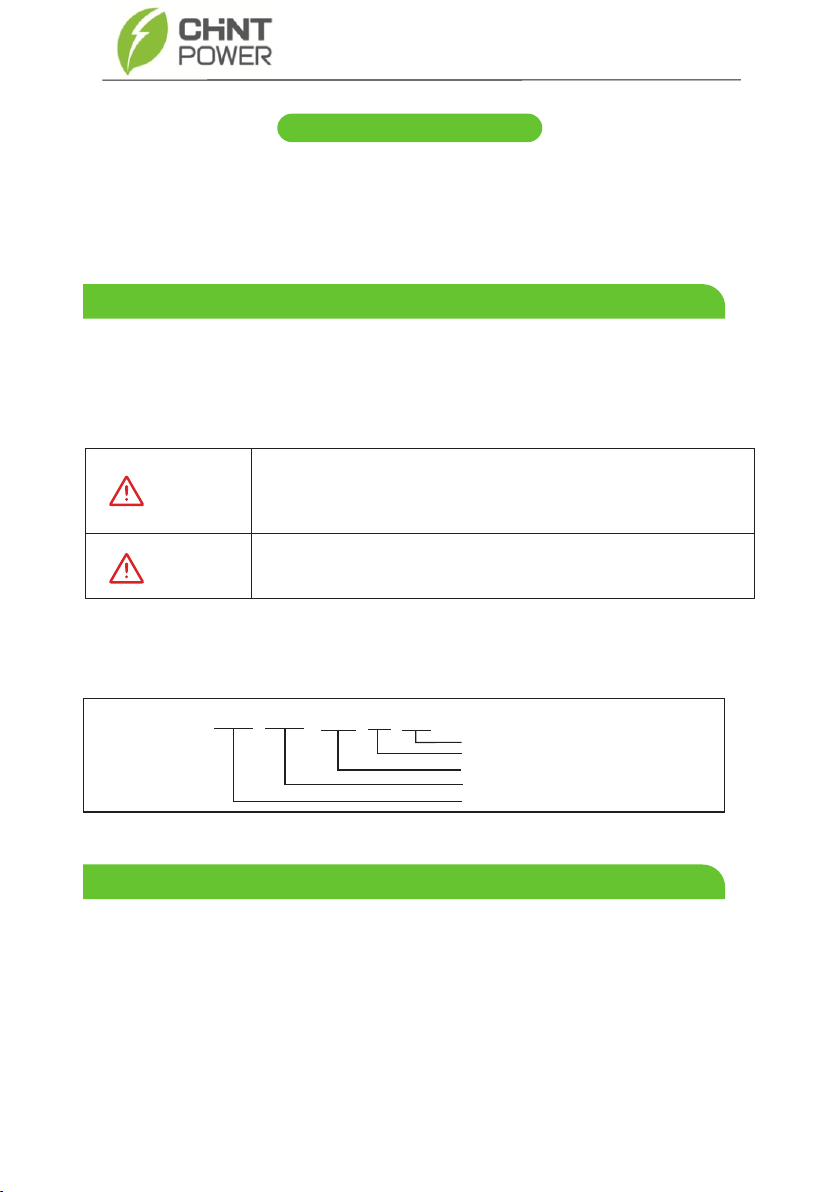
Figure 2.1 shows a model number of the inverter, using xK as an example.
Figure 2.1 Model number descriptions
CPS SCA xK TL - T
Product series
Transformerless
T-Three Phase
Chint power systems
Rated AC output power
2.2.1 Grid-tied PV Power Systems
2.2 Network Application
2.1 Functional Models
7
Figure 2.2 a low-voltage grid-tied PV power system
PV strings inverter AC Distribution Unit low-voltage power grid
This series inverters supports TN-S, TN-C, TN-C-S and TT power grids as shown in Figure 2.3.
Inverter
L1
L2
L3
N
PE
PE
Inverter
L1
L2
L3
PEN
PE
Inverter
L1
L2
L3
N
PE
PE
TT
Inverter
L1
L2
L3
N
PE
PE
Figure 2.3 Power grids supported by this series inverters
The enclosure dimensions of this series products are shown as Figure 2.4.
Figure 2.4 The dimensions of the inverter by front & side views (unit: mm)
CPS SCA-T Series Inverter
2.3.1 Outline
2.3 Outline and Dimensions
855
565
276.5

8
Figure 2.7 The bottom view of the inverter
Figure 2.5 The front view of LED indicator area
2. Grid Indicator
3. COM Indicator
4. Warning Indicator
Figure 2.6 The rear view of the inverter
Figure 2.5 shows the LED indicator area as follows:
1. PV Indicator
1. DC switch
2. Vent valve
3. PV strings connectors
4. Communication interface
5. RS485
6. AC output connectors
7 Fans.
CPS SCA-T Series Inverter
Reserved for installing rear panel
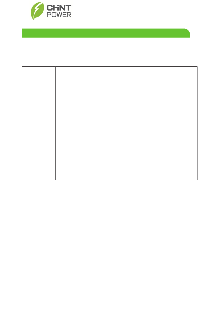
Table 2.1 Working modes description
There are three working modes of the inverter shown as follows: standby, operating, and shutdown.
Table 2.1 shows the conditions of the inverter switching between working modes.
The PV inverter enters the standby mode when the input voltage of
PV strings can enable auxiliary power supply to run, but cannot meet
the inverter operation requirements.
When the PV inverter is on-grid and generates electricity, it tracks the
maximum power point to maximize the PV String output and converts DC
power from PV strings into AC power and feeds the power to the power
grid.
Modes
Standby
Operating
Description
The PV inverter switches from standby or operating mode to shutdown
mode if detecting a shutdown command. And the shutdown command
can only be cleared when the DC side is powered off and restarted or
the boot command is received.
Shutdown
CPS SCA-T Series Inverter
2.4 Working Modes
9

10
If you do not use the inverter immidiately, please follow the requirements below to keep
the inverter for proper performance in futher use.
•Do not unpack the inverter (put desiccant in the original packing box if the PV inverter
is unpacked).
•Store the PV inverter at a temperature range of -40℃ to +70℃ with the relative
humidity of 0% to 100% (no condensation).
•A maximum of four layers of cartons can be stacked.
•Carton should not be left in a lop-sided position or turned upside down.
•Ensure that the inverter be inspected and tested by qualified personnel before use if
it has been stored for a long time.
CPS SCA-T Series Inverter
3 Storage

11
a. When receiving the inverter, check that the packing materials are intact.
b. After unpacking, check that the deliverables are complete, intact, and consistent with your
order list.
c. Examine the PV inverter and its fittings for damage such as scraps and cracks.
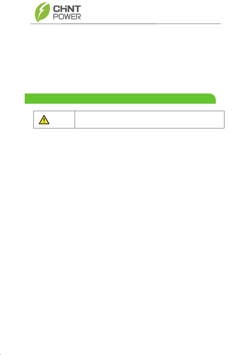
Do not mount the inverter in areas containing highly flammable
materials or gases.
The mounting location must be inaccessible to unrelated
personnel to avoid electrical shock burn.
CAUTION
DANGER
If any damage mentioned above is found, contact the dealer
immediately.
NOTICE
The inverter
Rear panel
File package
DC terminal connector group 30K (10*2)/36K (12*2)
M6 screws
Items Deliverables
CPS SCA-T Series Inverter
4 Installation
4.1 Checking the Outer Packing
12
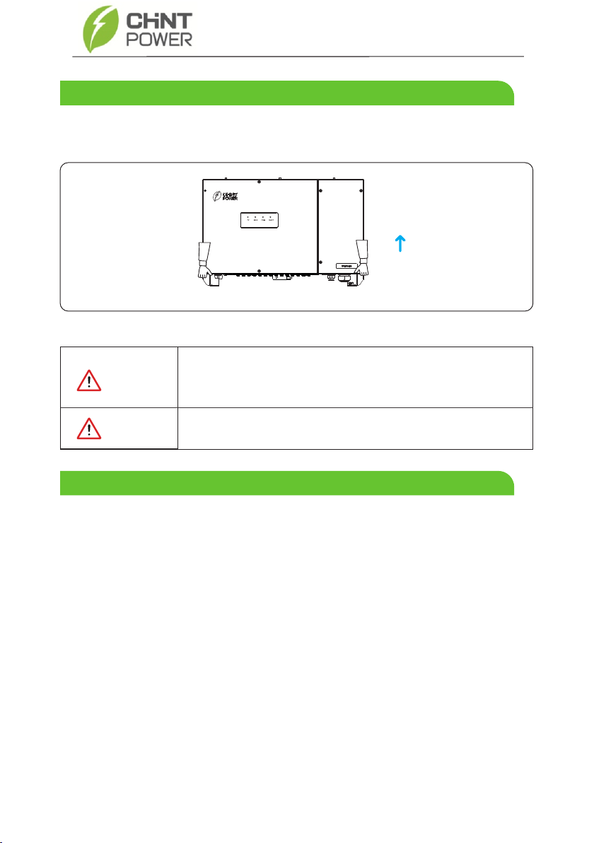
as shown in Figure 4.1.
Figure 4.1 Moving the inverter
To avoid damage or scratches of the inverter, please place the
inverter horizontally on a piece of foam or cardboard, and make
sure all ports bear no heavy pressure.
After moving the PV inverter from packing box, identify it by reading its nameplate labeled on
the side of the inverter. The nameplate contains important product information: the model
information, communication/technical data, and compliance symbols.
CAUTION
After checking the outer packing, move the PV inverter to the designated installation position,
Please handle the device with care to prevent slipping and personal
injury during transportation.
CAUTION
CPS SCA-T Series Inverter
4.2 Moving the Inverter
4.3 Identifying the PV Inverter
4.3.1 Nameplate
13
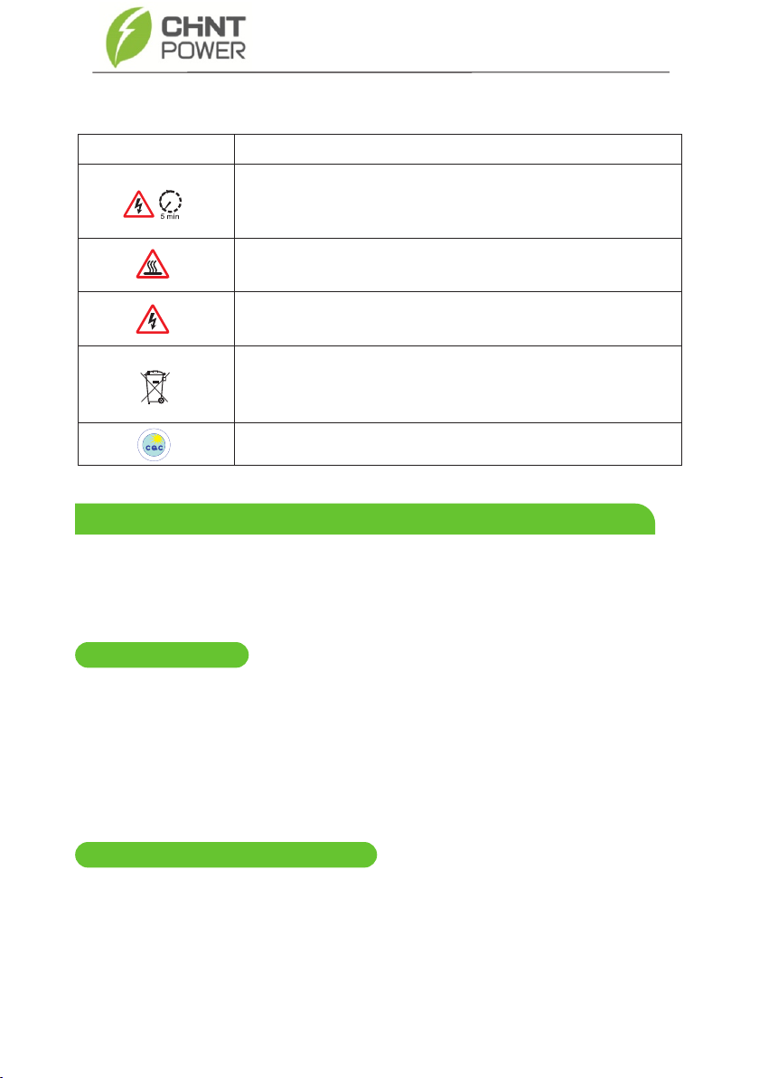
Electrical shock!
There are residual voltages in the PV inverter. It needs 5 minutes
to finish discharge.
The PV inverter must not be touched when in operation. Its
enclosure and heat sinks are extremely hot.
Electrical shock! This part is charged. Only qualified and / or trained
electrical technicians are allowed to perform operations on the inverter.
If the inverter service life has expired, dispose it in accordance with
local rules for disposal of electrical equipment waste. Do not dispose
the PV inverter with household garbage.
The PV inverter is compliant with CQC.
Safety symbol Description
能
产
认
阳
证
太
品
中
心
国
中
质
量
认
证
CPS SCA-T Series Inverter
4.3.2 Compliance and Safety Symbols
4.4 Installation Requirements
Applies to support-mounting installation, as described below in detail.
a. To ensure optimum operation and long service life, the ambient temperature must be
below 50℃.
4.4.1 Determining the Installation Position
Basic Requirements
Installation Environment Requirements
The inverter protection class is IP65 and can be mounted indoors or outdoors.
The mounting method and location must be suitable for the weight and
dimensions of the inverter (refer to 12 Technical Specifications).
The mounting location must be inaccessible to unrelated personnel since the
enclosure and heat sinks are extremely hot during operation.
Do not install the inverter in areas containing highly flammable materials or gases.
a.
b.
c.
d.

14
Figure 4.2 Installation environment with awning (unit: mm)
a. The mounting location should be freely and safely accessible at all times without the
need for any auxiliary equipment (such as scaffolding or lifting platforms).
Non-fulfillment of these criteria may restrict servicing.
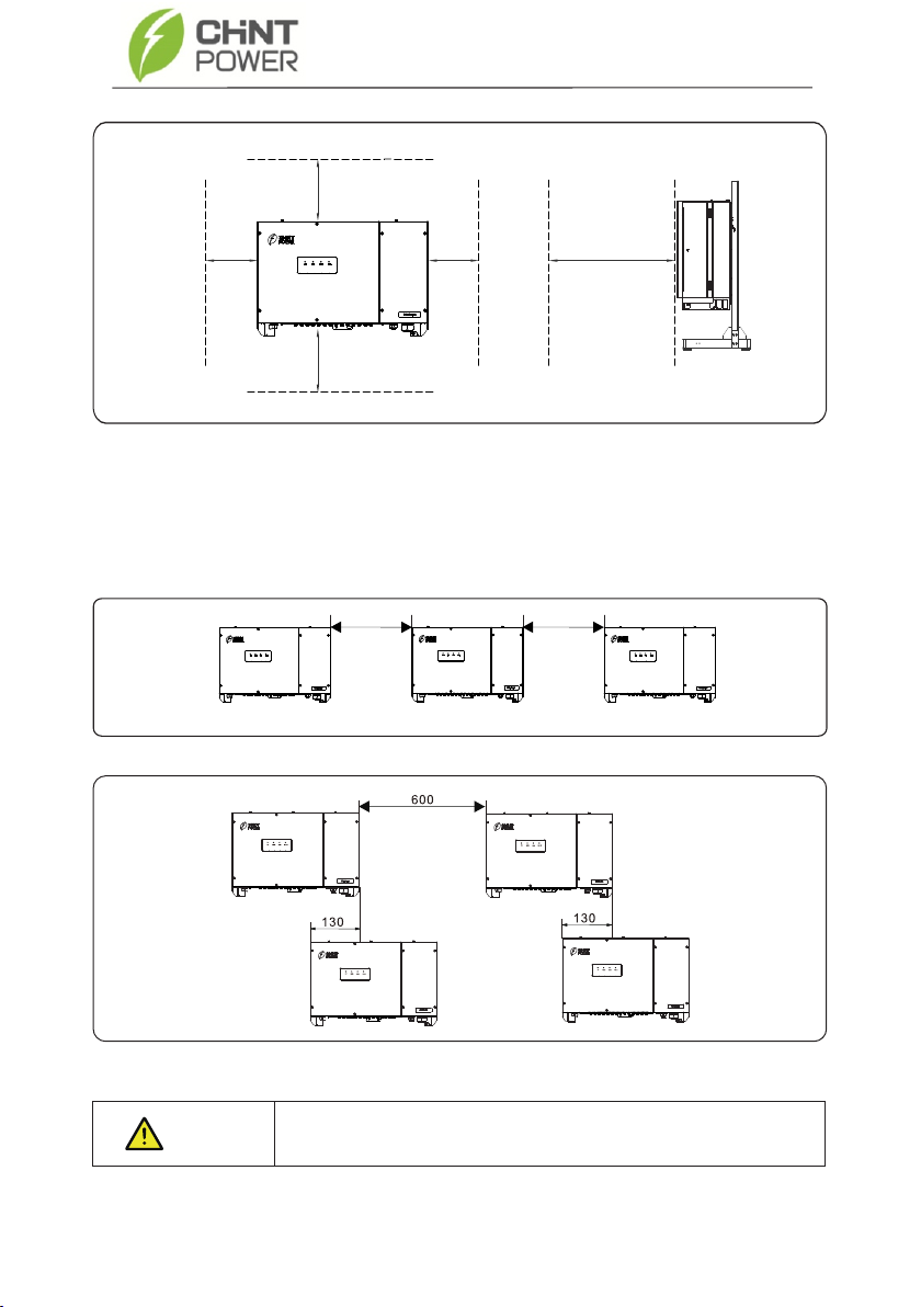
b. Reserve enough clearance around the inverter to ensure sufficient space for installation
and heat dissipation, as shown in Figure 4.3.
a. The carrier where the inverter is mounted must be fire-proof. Do not mount the inverter on
flammable building materials.
b. The wall must be solid enough to bear the weight of the inverter.
c. Do not install the inverter in a residential area since it will cause noise during operation.
the front view
Awning
the lateral view
≥500
≥1000
CPS SCA-T Series Inverter
Carrier Requirements
Installation Space Requirements
b. The inverter must be mounted in a well ventilated environment to ensure good heat dissipation.
c. To ensure long service life, the inverter must not be exposed to direct solar irradiation, rain,
or snow. It is recommended that the inverter be mounted in a sheltered place. If no shelter is
available, build an awning, as shown in Figure 4.2.
the front view the lateral view
Figure 4.3 Installation space requirements (unit: mm)
Figure 4.4 Mounting along the same line (unit: mm)
15
200 200
CPS SCA-T Series Inverter
c. When installing multiple inverters, there are three suggested installation methods as follows
in considering the installation space and heat dissipation.
Please install them along the same line (as shown in Figure 4.4) if sufficient space is available;
Please install them in stacked mode (as shown in Figure 4.5) if there is no sufficient space.
>600
>400>400
>600
>1000
Figure 4.5 Installation in stacked mode
The clearance between multiple inverters must be increased to
ensure proper heat dissipation when they are installed in a hot area.
NOTICE

16
Mount the inverter upright or at a maximum back tilt of 15 degrees to facilitate heat dissipation.
Some correct/wrong mounting modes, as shown in Figure 4.6 & 4.7.
Figures 4.6 The correct mounting modes
upright Lean back
Figure 4.7 The wrong mounting modes
Incorrect installation will result in the inverter not working properly.
NOTICE
The wrong installation mode
Horizontally Upside-down
Figure 4.8 Drill holes on the wall
The correct installation mode
CPS SCA-T Series Inverter
4.4.2 Installation Mode Requirements
4.5 Support-mounting the Inverter
Step 1 Drill holes on the wall, knock the expansion screw into the wall. Remove the flat washer,
spring washer and nut of the expansion screw for spare, as shown in Figure 4.8.
17
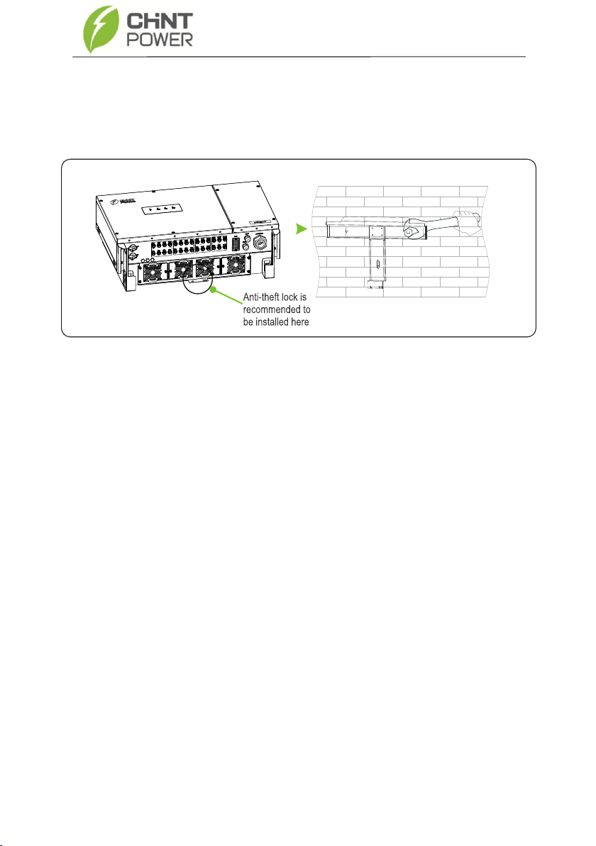
Figure 4.9 Mounting the inverter
Check the following items when installation is completed:
Step1: Ensure that the three supporting points (on the rear side of the inverter) align with
the three holes of the support.
Step2: Ensure that the inverter is well fixed.
Step3:Ensure that the inverter is locked on the support and an antitheft lock is installed.
CPS SCA-T Series Inverter
Step 2 Install the rear panel on the wall using M12 expansion screw after put on the flat washer,
spring washer and nut respectively and the required torque is 42N.m. Mount the inverter on the
rear panel and keep them aligned with each other. After that, tighten the screw between the
machine and the rear panel, as shown in Figure 4.9.
Other manuals for CPS SCA-T Series
1
This manual suits for next models
2
Table of contents
Other CHNT Power Inverter manuals


Popular Inverter manuals by other brands


TECO
TECO e510 series quick start guide

Juta
Juta MPPT-20 user manual

Hyundai
Hyundai N800 Series installation manual

Westinghouse
Westinghouse WPro8500 quick start guide

Morningstar
Morningstar SureSine 150 W quick start guide

Stanford Research Systems
Stanford Research Systems DS360 Operating manual and programming reference


