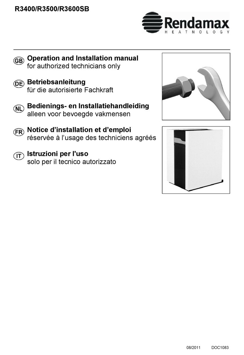
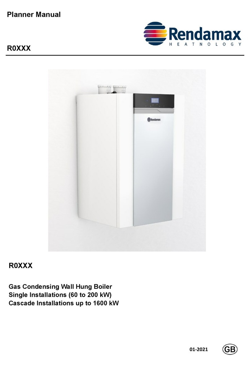
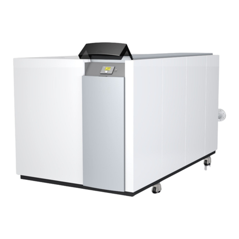
Rendamax R40 ECO User manual

1
Operating Manual
for authorized technicians only
R40 ECO
www.rendamax.com 9B.51.20.00 / 01.18

2
Table of contents
Table of contents .................................................................... 2
Safety regulations General regulations..................................... 3
Intended use ............................................... 3
Standards and regulations .......................... 3
Construction Product description / Functional
description - R40 ECO .............................. 4-6
Technical data Technical data / ERP data........................... 7
Dimensions.................................................. 8
Delivery scope Standard version / Accessories .................. 9
Cascade / Cascade accessories................. 10-11
Installation Boiler transport............................................ 13
Disassembly of panelling............................. 13
Installation ................................................... 14
Cascade Cascade wall mounted in line...................... 15
Cascade free-standing in line...................... 16
Cascade free-standing back-to-back........... 17
Connecting the boiler .................................. 18
Cascade accessories .................................. 19
Connecting 1 or 2 boilers ............................ 20
Dimensions headers, low loss headers
and bends.................................................... 21
Heating water quality................................... 22-23
Expansion vessel ........................................ 23
Gas line ....................................................... 24
Condensate connection............................... 25
Air-/uegasducts...................................... 26-31
Electrical connection ................................... 32-34
Externalcontrolson/o-OpenTherm ......... 35
External connections 0-10 Volt.................... 36
Wiring diagram ........................................... 37-38
Operation Description of display and keyboard ........... 39-40
Main functions of control panel.................... 40
Commissioning Start up ....................................................... 41
Display read-out / Boiler addresses ............ 42
Basic operations / Selecting programs........ 43
Settingthemax.owtemp.on/ocontrol ... 44
Filling the heating system............................ 45
Menu structure end user / technician .......... 46-47
Clock program / heating line........................ 48
Parameters End user / technician................................... 49-53
Activate factory settings .............................. 54
Commissioning Inspection and maintenance ....................... 55
Emmission check ........................................ 56
O2/ CO2check ............................................ 57-59
Maintenance Repair works ............................................... 60
Decommissioning ....................................... 60
Inspection interval ...................................... 60
Maintenance interval ................................... 60
Maintenance details .................................... 60-63
Counter running hours................................. 64
Inspection overview .................................... 65
Maintenance overview ................................ 66
Errors .................................................................... 67
Sensor parameters .................................................................... 68
System water additives .................................................................... 69
Conformity declaration .................................................................... 70 Version:
from sv 4.2
02-2016

3
Safety regulations
General regulations
Intended use
Standards and regulations
General regulations
This document contains important
information with regard to safety and
reliability of the installation, its com-
missioning and the operation of the
R40 ECO boiler. All described activities
must be carried out exclusively by
authorized technicians.
Only OEM parts of the boiler manufac-
turer may be used; in contrary cases,
our warranty and guarantee provisions
are excluded.
Intended use
The R40 ECO is a condensing and
modulating gas boiler, which is
suspended from walls and is delivered
with a pre-mix burner. The maximum
target temperature of the boiler is 85°C.
Standards and regulations
All applicable standards (both
European and national) must be
observed during the installation and
operation of the R40 ECO boiler,
including:
- Local building regulations, with
regard to the installation of heating
facilities and waste gas exhaust
systems;
- Regulations about a connection to
the electrical utility network (mains);
- Regulations of the local gas utility;
- Standards and regulations
concerning safety facilities for
heating systems;
- Additional local laws/regulations,
which are applicable to the
installation and operation of heating
systems.
- See the chapter “Commissioning”,
for those regulations applicable
to heating water and warm water
quality.
The R40 ECO boiler is CE-certied
and conforms to the following
European directives and standards:
- 92/42/EEC(Eciencyofhot
water heating systems)
- 2009 / 142 / EEC (Gas consuming
facilities)
- 2006 / 95 / EEC (Safety of electrical
operating resources)
- 2004 / 108 / EEC (EMC
compatibility)
- EN 15420 (Requirements for gas-
redsystems–typeCboiler70kW
–1000kW)
- EN 15417 (Special requirements for
condensinggas-redboilers70kW
–1000kW)
- EN 50165
Electrical equipment for non-electric
appliances, intended for household
use and similar purposes - safety
requirements
- EN 15502-1 (Requirements for
gas-redsystems–Part1:General
requirements and tests)
- EN55014-1(2000)EMC–
Requirements for household
appliances, electrical tools and
similarequipment–Part1:
Emissions
- EN55014-2(1997)EMC–
Requirements for household
appliances, electrical tools and
similarequipment–Part2:Safety-
product family standard
- EN 61000-3-2 (2000)
Electromagnetic compatibility
(EMC) - Part 3-2: Framework
conditions - framework conditions
forcurrentuctuations(current
drain 16 A per phase)
- EN 61000-3-3 (2001)
Electromagnetic compatibility
(EMC) - Part 3-3: Framework
conditionsforvoltageuctuations,
voltagelossandickerinpublic
low-voltage networks, for equipment
with a nominal 16 A current per
phase, which are not subject to any
special connection regulations.
- EN 60335-1 (2002) Household
and similar electrical equipment
- Safety - Part 1: General
requirements
- EN 60335-2-102 (2006) Household
and similar electrical equipment
- Safety - Part 1: Special
requirements for gas, oil and solid
fuel-redequipmentwithelectrical
connections
It is necessary that the currently
valid local normatives will be
observed.
UK:
- Gas Safety Installation & Use
Regulations
- BS 5440-1:2008
- BS 5440-2:2009
- BS 6798:2014
The facility may only be operated by
authorized persons, who have been
trained with regard to the functions
and the use of the system. Inexpert
use can damage the equipment or
the connected system.
The equipment may not be used
by children, by persons with a
hindrance of bodily, mental or
sensory capacities, or which
insucient experience and know-
how, unless they are supervised
or have received corresponding
instructions.
It must be ensured that children
cannot play with the equipment.
If changes are made to the boiler
construction the boiler no longer
complies with the CE requirements.

4
Product description
R40 ECO
1
2
3
4
5
6
7
8
10
9
11
12 13
14
3
4
5
6
7
G C A R
15 16
18
17
22
21
20 19
T1a
T2
P1
T1

5
Product description
The R40 ECO is a condensing and
modulating gas boiler with one or two
pre-mix burners, which is attached to a
wall. It is characterized by the following
features:
- A large modulation range that
guarantees a long burner service
life, while minimizing standby
losses, start-up emissions and
material wear-and-tear.
- Flue gas temperature below 80°C
- Flue gas temperature fuse
- Also suitable for room sealed
conditions
- Control panel with all operational
elements
- Microprocessor, with multi-
functional display
- Automated ignition, with repetition
and ionization monitoring
- Water pressure monitoring
- Energy-saving pump
- Stainless steel heat exchanger with
smooth tube condenser
- Very maintenance-friendly
- Ready for weather-compensated
control (accessory)
- Cascadecontroller up to 8 boilers
- External controls (accessory) by on/
o,OpenThermor0-10V
- Modern metal panelling, stove-
enamelled
Functional description
Thecontrolunitmodiestheheating
performance to the current heating
requirements, by changing the
default values of the fan rotating
speed.Inthisregard,theboilerow
temperature is continually measured
via a sensor. In case of a deviation of
the actual temperature from the target
temperature, the control unit reacts
immediately and adjusts the RPM
of the fan, and with that the boiler
performance via the gas armature. A
deviation can be due to:
- A changed default value of the
boiler temperature, via the SITT
heating control unit
- A change on the outdoor
temperature
- Request for warm water
- Changed heating curve
By means of the integration of the
individual components in a system,
and within the control range of the
equipment, it is ensured that the boiler
performance always corresponds to the
actual heating requirements.
Delivery scope
The boiler, which has been assembled
at the factory and is ready to use,
is delivered in cardboard packaging.
The following is contained in the
delivery scope of the R40 ECO:
- Modulatinghigheciencygas-red
boiler, 8,8 to 120kW
- Higheciencypump(s)
- Boiler/Cascade controller
Accessories:
- Boilerconnectionttings
- Headers for 2 and 3 boilers
- Low loss headers up to 960kW
- Insulation packs
- Boiler frames for free standing units
For detailed information see pages
11-12.
Legend:
1 heat exchanger 1 (All types OSS4)
2 heat exchanger 2 (R40 ECO100:
OSS2, R40 ECO120: OSS4)
3 ignition unit
4 fan unit
5 silencer
6 gas valve
7 automatic air vent
8 main switch 230V
9 boiler control unit
10 control unit MMI
11 connection terminal
12 connection terminal cascade bus
communication
13 siphon
14 circulation pump
15 gas isolation valve (in optional
boiler connections set)
16 servicevalvesow/return(in
optional boiler connections set)
17 llanddrainvalve(inoptional
boiler connections set)
18 safety valve (in optional boiler
connections set)
19 ueconnection(concentric)
20 airsupply(forparallelue
connection)
21 collectiveuepipe
22 information plate
T1 owsensor
T1asecondaryowsensor(only
OSS4)
T2 return sensor
P1 water pressure sensor
G gas pipe
A owpipeCH
R return pipe CH
C condensate drain pipe
Product description
R40 ECO

6
Product description
R40 ECO hydraulic circuit diagram
R
OK
-
+
R
OK
-
+
T1
T2
P1
T1a
T1
T2
P1
T1a
G C A R
1
3
6
58
7
4
15 14
910
11 11
8
2
3
6
5
7
4
9
Burner A
Burner B
Legend:
1 heat exchanger 1 (All types OSS4)
= burner A
2 heat exchanger 2 (R40 ECO100:
OSS2, R40 ECO120: OSS4) =
burner B
3 ignition unit
4 ceramic burner
5 gas valve
6 fan
7 uenon-returnvalve
8 automatic air vent
9 circulation pump
10 control unit MMI
11 burner control unit
T1 owsensor
T1asecondaryowsensor(only
OSS4)
T2 return sensor
P1 water pressure sensor
G gas pipe
A owpipeCH
R return pipe CH
C condensate drain pipe

7
Product description
Technical data
ErP data
Type R40 ECO 70 100 120
Permit
Category
CE0063CM3648
II2H3P
Heat exchanger type OSS4 OSS4
OSS2
OSS4
OSS4
Output G20 Full load 80/60°C kW 60,1 95,0 120,0
40/30°C kW 65,0 102,3 129,3
Low load 80/60°C kW 8,8 14,8 17,6
40/30°C kW 9,9 16,6 19,6
G31 Full load 80/60°C kW 60,1 95,0 120,0
40/30°C kW 65,0 102,3 129,3
Low load 80/60°C kW 30,2 46,8 62,5
40/30°C kW 34,0 52,4 69,7
Input G20 Full load kW 61,8 97,3 123,0
Low load kW 9,0 15,2 18,0
G31 Full load kW 61,8 97,3 123,0
Low load kW 31,0 48,0 64,0
Boilereciency Full load 80/60°C % 97,3 97,6 97,6
Low load 40/30°C % 109,8 109,2 108,9
Gas type Natural gas or Propane gas
CO2natural gas min./max. Vol. % 8,8 / 9,2
CO2propane gas min./max. Vol. % 10,5
O2natural gas min./max. Vol. % 4,6 / 5,4
NOx class 5 5 5
Max.uegastemperature 80/60°C 76 73 77
Massowofuegas max. g/s 28,2 43,4 56,2
Overpressure at boiler output max. Pa 175 195 195
Water volume in heating circuit l 7 12 15
Weight kg 54 72 76
Gasowpressure-standard mbar 20
Gasow-pressuremin./max. mbar 17 / 25
Operating pressure of heating unit min./max. bar 0,7 / 4
Voltage/frequency min./max. Volt/Hz 230 / 50
Max. power consumption W 161 250 322
Power consumption part load W 44 86 88
Power consumption stand by W 2,5 3,7 3,7
Width / depth / height mm 660 / 460 / 1065
External thread of gas connection R 1 1/4" 1 1/4" 1 1/4"
Flow/return external thread R 1 1/2" 1 1/2" 1 1/2"
Flue gas connection PPS Diameter DN 100 100 100
Outdoor air connection Internal Ø mm 100 100 100
Condensate connection PVC External Ø mm 26 26 26
Elco
Type R40 ECO 70 100 120
ErP data according to 2010/30/EU
Seasonalroom-heatingenergyeciencyclass A
Nominal heat output Pn(kW) 60 92 120
Seasonalroom-heatingenergyeciencyclass ηs(%) 94 94 94
Annual energy consumption QHE (GJ) 20 30 39
Noise output level, inside LWA (dB) 51 52 53
At rated heat output and high-temperature regime (80/60°C) P4 (kW) 60,1 92,5 112,9
At 30 % of rated heat output and low-temperature regime (36/30°C) P1 (kW) 20,6 31,6 38,6
At rated heat output and high-temperature regime (GCV) η4(%) 87,7 87,8 87,8
At 30 % of rated heat output and low-temperature regime (GCV) η1(%) 99,3 99,4 99,4
At full load elmax (kW) 0,161 0,250 0,250
At part load elmin (kW) 0,004 0,009 0,009
In standby mode Psb (kW) 0,003 0,003 0,005
Standby heat loss Pstby (kw) 0,110 0,110 0,110

8
Product description
Dimensions of R40 ECO
Type R40 ECO 70 100 120
A Boiler height mm 1066 1066 1066
A! Boilerheightwithueconnection mm 1151 1151 1151
B Boiler width mm 660 660 660
C Boiler depth mm 460 460 460
D Flue gas nozzle mm 465 465 465
E Air intake parallel mm 315 315 315
F Flue gas nozzle mm 345 345 345
G Air intake parallel mm 165 165 165
H Feedthrough power supply cable 230V mm 105 105 105
J Gas connection mm 180 180 180
K Condensate connection mm 275 275 275
LBoilerowconnection mm 370 370 370
M Boiler return connection mm 510 510 510
N Length siphon mm 237 237 237
P Pipe lenght of g, v, c and r mm 30 30 30
Q Boiler connections g, v, c and r mm 50 50 50
R Feedthrough power supply cable 230V mm 100 100 100
C
E
F
A
N
P
Q
R
D
H
J
K
G
L
M
Ceiling
A1
B
Boiler connections
Type R40 ECO 70 100 120
Flue gas nozzle concentric mm 100 100 100
Air supply connector concentric mm 150 150 150
Parallel connection mm 2x 100 2x 100 2x 100
g Gas connection 1 1/4" 1 1/4" 1 1/4"
c Condensate connection mm 26 26 26
vBoilerowconnection 1 1/2" 1 1/2" 1 1/2"
r Boiler return connection 1 1/2" 1 1/2" 1 1/2"
Individualue:
min. 400mm
Collectiveue:
dependant on
the selected
uesystem.
Please contact
the supplier
g c v r

9
Delivery scope
Standard version
Accessories and Cascade
Standard version
The delivery scope of a boiler consists
of the following components:
Components Packaging type
Completely assembled and tested boiler 1 In cardboard box
Mounting rail 1 In boiler packaging
Operating manual R40 ECO technician 1
In document bag in boiler packaging
Operating manual R40 ECO operator 1
Replacement part list 1
ERP label (only R40 ECO 70) 1
Accessories
The following accessories can be
ordered:
- Flue gas pipes
- Cascade hydraulics (see following
pages)
- Boiler frames (see following pages)
- 3-way valve set
- Outdoor sensor
- T10owsensor
Listed accessory parts have been a
specially constructed or selected for
the R40 ECO boiler, which means they
are very easy to install (plug and play).
You can compose your own system
solution, by selecting the accessory
combinationthattsyourneeds.For
details and prices, please contact
Rendamax.
Cascade
In principle any combination is
possible. Based on the requested
capacity, you can choose either the
mostecientorthemostcompact
solution yourself.
The capacity of the hydraulic pipes, gas
line and low loss header are adjusted
to the selected overall demand.
When installing a single R40 ECO
boiler or cascaded R40 ECO boilers,
you should always use a low loss
header adjusted to the set demand.
Rendamax supplies 3 low loss
header versions, which are suitable
for a maximum demand of either
200kW, 452 kW or 960kW (80/60°C)
respectively.

10
Product description
R40 ECO Cascade
Legend:
1 Airsupply(forparallelue
connection)
2 Flue/Air supply (concentric)
3 Cascade manager
Accessories:
3 Gas isolation valve
4 Servicevalvesowandreturn
5 Non-return valve
6 Flow/return header
7 Gas line
8 Low loss header
9 Safety valve 4 bar
10 Fill and drain valve
11 Automatic air vent low loss header
12 Pocket for temperature sensor T10
13 Frame
1 2
3 4 5 6 78 10 9
11
12
3
13
Cascade possibilities
The Rendamax R40 ECO cascade can
be mounted in 3 ways:
- Wall-mounted in line
All boilers alongside one another on
the wall
(Example 2 boilers wall-mounted in
line)
- Free-standing in line.
All boilers hanging alongside one
another on a free-standing frame
(Example 2 boilers free-standing in
line)
- Free-standing back-to-back.
All boilers hanging back-to-back on
a free-standing frame
(Example 4 back-to-back)
1430
660
1070
460
1715
1000
1070
460
1715
540
1430
660
1430
660
1070
460
1715

11
Product description
R40 ECO Cascade accessories
18 15
29 16
3 10 17
411 18
512 19
613 20
7 14 21

12
Type R40 ECO Part no. 70 100 120
1 Wall mounting rail for 2 boilers 3905023 x x x
Wall mounting rail for 3 boilers 3905024 x x x
2 L- post 3905022 x x x
3 I-post 3905021 x x x
4 Boiler frame 3905025 x x x
5Headerow/returnDN65+gasDN502/4 3905017 x x x
Headerow/returnDN100+gasDN652/4 3905018 x x x
6Headerow/returnDN65+gasDN503/6 3905019 x x x
Headerow/returnDN100+gasDN653/6 3905020 x x x
7Lowvelocityheader≤452kWDN65 3905033 x x x
Lowvelocityheader≤960kWDN100 3905034 x x x
8Lowvelocityheader≤200kW1or2boilers 3905048 x x x
990°bendsetow/returnDN65 3905035 x x x
90°bendsetow/returnDN100 3905036 x x x
10 BlindancheDN65F/R2x 3905026 x x x
BlindancheDN100F/R2x 3905027 x x x
11 BlindanchegasDN501x 3905028 x x x
BlindanchegasDN651x 3905029 x x x
12 WeldanchesetDN65F/R2x+gasDN501x 3905037 x x x
WeldanchesetDN100F/R2x+gasDN651x 3905038 x x x
13 Boiler connection set line 3905030 x x x
14 Boiler connection set back to back 3905031 x x x
15 DHW connection set incl. 3 way valve 3905032 x x x
16 Connection set solo 3905049 x x x
17 Connection set solo incl. 3 way valve 3905061 x x x
18 Three way valve 3905060 x x x
19 Insolation set header DN100 (modulair) set of 2 3905039 x x x
20 Insolationsetlowvelocityheader≤960kW 3905040 x x x
21 Insolation set 90° bend set F/R DN65 3905041 x x x
22 Insolation set boiler connection set line 3905042 x x x
23 Airlter 3905046 x x x
Cartridgeairlter 3905047 x x x
24 Bus communication cable 3905043 x x x
Bus communication extension cable 3905044 x x x
25 Outside sensor (T4) 171237 x x x
26 Temperature sensor low velocity header (T10) 3905045 x x x
Product description
R40 ECO Cascade accessories
22
23
24
25
26

13
Installation
Boiler transport
Boiler transport
The R40 ECO is a fully equipped
compact heating system, which has
been pre-set and tested at the factory.
The dimensions of the packaging are:
- 70, 100, 120:
1200 x 800 x 670 mm (WxHxD)
This makes it possible to transport all
models in one piece through a normal
door. The boiler can be picked up
sideways or from the front with a forklift
truck for transport.
The R40 ECO can be transported
with a crane. However, it must be
ensured that the boiler is attached in
its packaging to a pallet. Loading belts
should be attached to the pallet.
Unpacking instructions are printed on
the cardboard box. Please follow the
proposed steps.
Disassembly of panelling
The panelling has been packed
separately from the boiler in the
packaging. The panelling of the
boiler should be set aside, before the
assembly and until the boiler is taken
into operation, so as to avoid damage.
Panelling should be attached and
1 2 3
46
5a
5b
4x
1 2 3
46
5a
5b
4x
secured with the supplied screw,
after assembly of the boiler, or after
maintenance works.
Lifting and carrying precautions:
- Lift only a manageable weight, or
ask for help.
- When lifting the boiler, bend the
knees, and keep the back straight
and feet apart.
- Do not lift and twist at the same
time.
- Lift and carry the boiler close to the
body.
- Wear protective clothing and gloves
to protect from any sharp edges.

14
Installation
Installation
Connections
The installation location of the CH-
boiler(s) has to be, and remain, frost-
free.
It is NOT necessary to have a purpose
provided air vent providing a twin pipe
orconcentricroomsealeduesystem
is used in the room or internal space in
which the boiler is installed. Neither is it
necessary to ventilate the compartment
in which the boiler is installed, due to
the extremely low surface temperature
of the boiler casing during operation.
Theoorhastobeatandleveland
havesucientdeadweightcapacityfor
thecomplete(lled)installation.
The Rendamax R40 ECO cascade can
be mounted in 3 ways:
- Wall-mounted in line
All boilers alongside one another on
the wall. Refer to page 15.
- Free-standing in line
All boilers hanging alongside one
another on a free-standing frame.
Refer to page 16.
- Free-standing back-to-back.
All boilers hanging back-to-back
on a free-standing frame. Refer to
page 17.
General guidelines:
Pay attention to the minimum
distance required between the
boilers, walls and ceiling for
installing and removing the housing
(refer to g. 5.a.) for commissioning
and servicing and installing the ue
system (refer to chapter 7).
If you have opted to build the hydraulic
part yourself, then Rendamax
recommends using a boiler connection
set 3905049 (Connection set R40 ECO
as single boiler) for each boiler. In that
case, the connection measurements
are:
- Flow and return line:
ø35mmcompressiontting
- Gas line:
ø28mmcompressiontting
50mm
50mm
1000mm
4 1 2
5
3
1 Boilerowconnection
2 Boiler return connection
3 Condensate drain
4 Gas
5 Airsupply/uegas

15
Installation
Cascade wall mounted in line
A . Position the pipe work header
against the wall. When using
several pipe work headers: couple
the pipe work headers and supplied
gaskets, M12 (DN65) or M16
(DN100) bolts, spring washers and
nuts. Align the pipe work header(s)
horizontally using the adjustable
feet.
B. Determine the position of the
suspension brackets based on
gureB1.Theboilerscanbetted
on the wall using the supplied
suspension brackets and mounting
material (minimum of 3 screws for
each boiler). The wall has to be
atandstrongenoughtocarrythe
weight of all boilers including their
water contents.
C. Hang the boilers on the suspension
brackets.
Lift the boiler only by the special
grips on the bottom panel (1)
and support the boiler by its rear
panel (2).
1
1
22
D. Place the gas line in its intended
recess. When using several pipe
work headers: couple the gas lines
using the supplied DN50/DN65
gaskets, M12 bolts, spring washers
and nuts.
E. Fasten the gas line with the 2
special close tolerance bolts
M6x8x16 on each ange of the
pipe work header(s).
Continue with page 18.
A
B
C
E
B1
D

16
Installation
Cascade free-standing in line
A Position the pipe work header in
the required location. When using
several pipe work headers: couple
the pipe work headers using the
supplied gaskets, M12 (DN65) or
M16 (DN100) bolts, spring washers
and nuts. Align the pipe work
header(s) horizontally using the
adjustable feet.
B. Place the gas line in its intended
recess. When using several pipe
work headers: couple the gas lines
using the supplied DN50/DN65
gaskets, M12 bolts, spring washers
and nuts.
Fasten the gas line with the 2
special close tolerance bolts
M6x8x16 on each ange of the
pipe work header(s).
C. FittheI-columnsontheangeplate
using 2x bolts M8x40x70mm.
Attention: Use the correct holes
in the column!
When using a left ange plate:
use the right-hand holes in the
column.
When using a right-hand ange
plate: use the left-hand holes in
the column.
D. Fit a mounting frame on the
I-column using 3-x bolt M8x50mm.
Attention: mounting rail at the
top.
E. Fit a mounting frame on the other
I-column using 3-x bolt M8x50mm.
Ifboilersalsohavetobettedon
the other side of the I-column, then
the next mounting frame also has to
bettedstraightonit.
Fit the remaining I-column(s)
between the mounting frames using
3x M8x50mm.
F. Hang the boilers on the mounting
rail.
Lift the boiler only by the special
grips on the bottom panel (1)
and support the boiler by its rear
panel (2).
Continue with page 18.
1
1
22
OK
A
B
C
D
E
F

17
Installation
Cascade free-standing back-to-back
A. Position the pipe work header in
the required location. When using
several pipe work headers: couple
the pipe work headers with the
supplied gaskets, M12 (DN65) or
M16 (DN100) bolts, spring washers
and nuts. Align the pipe work
header(s) horizontally using the
adjustable feet.
B. Place the gas line in its intended
recess. When using several pipe
work headers: Couple the gas lines
using the supplied DN50/DN65
gaskets, M12 bolts, spring washers
and nuts.
Fasten the gas line with the 2
special close tolerance bolts
M6x8x16 on each ange of the
pipe work header(s).
C. FittheL-columnsontheange
plate using 2 x bolts M8x40x70mm.
Attention: Use the correct holes
in the column!
When using a left ange plate:
use the right-hand holes in the
column.
When using a right-hand ange
plate: use the left-hand holes in
the column.
D. Fit a mounting frame on the
L-column using 3x bolt M8x50mm.
Attention: mounting rail at the
top.
E. Fit a mounting frame on the other
L-column using 3-x bolt M8x50mm.
Ifboilersalsohavetobettedon
the other side of the L-column then
the next mounting frame also has to
bettedstraightonit.
Fit the remaining L-column(s)
between the mounting frames using
3x M8x50mm.
F. Hang the boilers on the front and
rear of the frame on the mounting
rail.
Lift the boiler only by the special
grips on the bottom panel (1)
and support the boiler by its rear
panel (2).
Continue with page 18.
OK
A
B
C
1
1
22
D
E
F

18
Installation
Connecting the boiler
A. Remove the remaining packaging
part from the bottom of the boiler.
Note: this packaging part is
provided with boiler parts which
are needed for mounting the
boiler.
B. Cap the connections that are not
used on the pipe work headers:
Flow and return:ø35mm blind
compressiontting(2items/boiler)
Gas: 1 ¼” blind cap with gasket
(1 item/boiler)
For connections, use the supplied
gaskets. Check all connections for
leakage and gas-tightness.
C. Connecting the isolation valves to
the boiler:
Flow:1½”atcouplingx35mm
compression isolation valve with
red handle
Return:1½”atcouplingx35mm
compressionttingcrossunionwith
ll/drainvalveandisolationvalve
with blue handle
The boiler is supplied with a 3 and 4
bar safety valve.
Rendamaxrecommendttingthe4
bar safety valve due to the control
settingsshuttingtheboileroat3.8
bar.
Gas: 1¼” x 28mm gas isolation
valve
Polluted test water may be
released when removing the
plastic caps on the boiler ow
and return.
For connections, use the
supplied gaskets. Check all
connections for leakage and gas-
tightness.
D. Connect the valves to the pipe work
headers:
Flow: 35mm pipe pieces with 35mm
compressionttings(elbowand
socket)
Return: 35mm pipe pieces with
35mmcompressionttings(elbow
and socket)
Gas:28mmpipepiecewith1¼”at
and28mmcompressiontting
Back-to-back installation:
Flow: 35mm pipe pieces with 35mm
compressionttings(bendand
socket)
Return: 35mm pipe pieces with
35mmcompressionttings(bend
and socket)
Gas:28mmpipepiecewith1¼”at
and28mmcompressiontting
For connections, use the
supplied gaskets. Check all
connections for leakage and gas-
tightness.
E. Fill the siphon with tap water and
tthesiphoncupunderneaththe
boiler.
The siphon cup is supplied
separately and can be found behind
the housing.
B
A
C
D

19
Installation
Cascade accessories
The pipe work headers are available
in 2 dimensions, i.e. DN65 and DN100
and are connected to one another
bytheangecouplingsandgaskets,
M12 or M16x55 bolts, spring washers
and nuts. The low loss header and
the complete installation can then be
connected to it.
Low loss header
There are 3 low loss headers available:
3905048
Low loss header for 1 or 2 R40 ECO
boilers to max. 200kW supplied
with automatic air vent, drain valve
and pocket for temperature sensor
T10 Boiler connections are 4x 1 ½”,
installation connections are 2x 2”. The
low loss header MUST be connected
between the boiler[s] and the system
pumps.
3905033
Low loss headers DN65 to 452kW
3905034
Low loss headers DN100 to 960kW
The low loss headers comes standard
with adjustable feet, automatic air vent,
drain valve, pocket for temperature
sensor T10, M12 or M16x55 bolts,
spring washers and nuts. The low loss
header can be positioned on either the
left or right hand side of the pipe work
headers.
3905045
Flow temperature sensor T10
Every system with 1 or more R40
ECO-boilers must be provided with a
owtemperaturesensorT10andmust
be connected on the master boiler
(address 01) to terminal 3, position 5
and6.Theowsensormustbeplaced
in the pocket of the low loss header.
Set of bends
The low loss header can be positioned
at a 90° angle. A set of bends may be
used for that purpose.
3905035
BendssetDN65ow/return
3905036
BendssetDN100ow/return
Blanking anges
The ends of the pipe work headers
havetobettedwithblankinganges.
Theblankingangescomestandard
withafullycongureddelivery,
including bolts, spring washers and
gaskets.
3905026
BlankingangesetDN65ow/return2
items
3905027
BlankingangesetDN100ow/return
2 items
Welded-on anges
Uponrequest,welded-onangesare
available to connect CH-pipe lines
to the secondary side of the low loss
header and to connect the gas line.
3905037
Welded-onangesetDN65ow/return
2items+DN50gas1item
3905038
Welded-onangesetDN100ow/
return2items+DN65gas1item
Required components that are not
supplied by Rendamax:
- The installation pump;
- The condensate discharge system
- Theinstallationwaterlter;
- Air and dirt separator;
- Gaslter;
- Hot water supply;
- Regulation valve;
- Flue system;
- Expansion vessel(s).

20
1x R40 ECO boiler, wall hung 2x R40 ECO boilers, wall hung,
max. 200kW
1x R40 ECO boiler, free-standing 2x R40 ECO boilers, free-standing,
max. 200kW
3/8” 1/2”
34
26
56
660
440
529
352
1 1/2” (4x)
48
1/2”
2” (2x)
Wall hung Free standing
Number of R40 ECO boilers 1 2 1 2
Necessary articles
3905022 L-shape frame for back to back alignment 2 2
3905021 I-shape frame for line alignment 1
3905025 Boiler frame 1 2
3905048 Low loss header for 1 or 2 boilers (max. 200 kW) 1 1 1 1
3905049 Boiler connection set for single boiler 1 2 1 2
3905043 Bus communication cable 1 1
3905045 Commonowsensor10kOhmT3/T10 1 1 1 1
Supplyofconnectionpipes,ttingsandbracketsbythirdparty.
Installation
Cascade accessories
Connecting 1 or 2 boiler boilers
Table of contents
Other Rendamax Boiler manuals
Popular Boiler manuals by other brands

Buderus
Buderus Logano G334 X instructions

Ferroli
Ferroli TEMPRA 24 Installation, service and user instructions

Vaillant
Vaillant ecoFIT sustain 415 Installation and maintenance instructions

Signature
Signature S024 instruction manual

Super Hot
Super Hot SG Series Installation and service manual

Viessmann
Viessmann VITOLIGNO 300-P Service instructions for contractors

klover
klover PB24 manual

elco
elco ADI CD 70 operating & maintenance manual

Keston
Keston 30C Installation and servicing instructions

Atag
Atag Blauwe Engel S-HR Series Installation and servicing instructions

REMEHA
REMEHA Gas 350 L Assembly instructions

ECR International
ECR International Dunkirk HELIX VX Installation, operation & maintenance manual