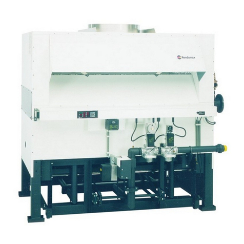
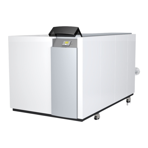
Rendamax R2000 Series Guide

TECHNICKÁ DOKUMENTACE
R2000
FLOW CLIMA, s. r. o.
Baarova 2, 140 00 Praha 4, Czech Republic
Tel.: +420 241 483 130
Fax: +420 241 483 129
Hviezdoslavova 55, 627 00 Brno
Tel.: +420 548 213 005
Fax: +420 548 213 016
www.rendamax.cz
www.flowclima.cz

2
Edition DOC2012, April 2007
2007 Rendamax
All rights reserved.
No part of this publication may be reproduced, stored in a retrieval system, or transmitted in any form or by any means,
electronic, mechanical, photocopying, recording or otherwise, without the prior permission in writing of Rendamax B.V.
We aim to achieve continuous improvement in our products. Therefore, specifications are subject to change without prior notice.
Due to changes the product can deviate from the information specified in this document. Therefore Rendamax B.V. rejects any
responsibility for the differences between the product delivered and the information mentioned in this document.
DOC2012/2000en

3
DOC2012/2000en
Index
R2000 Technical data R2017-R2048 5
R2000 Technical data R2056-R2122 6
Dimensions 7
1Introduction 8
1.1 Rendamax 8
1.2 Supplier 8
1.3 This manual 8
1.4 Service 8
1.5 General restrictions 9
2Description 9
2.1 General information 9
2.2 Main components 10
2.3 Principle of regulation 13
2.3.1 EM Control option 13
2.3.2 EW Control option 14
2.4 Boiler protection 17
3Safety 17
4 Delivery and transport 19
4.1 Delivery 19
4.2 Unit protective packaging 19
4.3 Transport 19
5Installation 20
5.1 Boilerroom 20
5.1.1Siting 20
5.1.2 Boiler room ventilation 20
5.2 Unit connections 20
5.2.1Gassupply 20
5.2.2Electricalsupply 21
5.2.3 Hydraulic connections 21
5.2.4Flues 22
5.3 Waterquality 23
5.4 Hydraulicsystem 24
5.4.1 Flow and resistance 24
5.4.2 Examples hydraulic system 27
6Commissioning 30
6.1 General 30
6.2 Pre-lighting checks and dry run 33
6.2.1Check1 33
6.2.2Check2 33
6.2.3Check3 35
6.3 Liveruncheck 35
6.4 Instructions to user 37

4 DOC2012/2000en
7 Operation and fault indication 37
7.1 Function 37
7.2 Regulation 37
7.3 Control panel 37
7.4 Fault indications 38
7.5 Start-up 39
7.6 Shut-down 39
7.7 Warnings 39
7.8 Fault finding table 40
8Maintenance 42
8.1 Safety 42
8.2 General information 42
8.3 Inspection 42
8.4 Cleaning 43
8.5 Servicing 43
8.6 Component replacement 47
8.7 Service 49
Notes 50

DOC2012/2000en
R2000 Technical data R2017-R2048
5
Type R2017 R2022 R2028 R2034 R2041 R2048
Nominal heat output
Nominal heat input (nett. CV) kW
kW 57,7
65,5 74,6
84,8 95,8
107,7 116,7
131,6 139,1
158,6 162,7
185,5
Gas consumption
natural gas H (10,9 kWh/m3)
propane
m3/h
m3/h
6,0
2,3
7,9
2,9
9,9
3,8
12,2
4,7
14,7
5,6
17,2
6,6
Gas inlet pressure (min.)
(max.)
propane (max.)
mbar
mbar
mbar
17
25
50
17
25
50
17
25
50
17
25
50
17
25
50
17
25
50
Water volume
Max. working pressure dm3
bar 5,6
11 5,9
11 6,2
11 6,5
11 6,9
11 7,3
11
Flue connection D mm 200 225 250 250 300 300
Gas connection G ¾” ¾” 1” 1” 1” 1”
Water connections W 2” 2” 2” 2” 2” 2”
Pressure relief valve
connection
relief connection
standard setting
bar
½”
½”
3
½”
½”
3
½”
½”
3
¾”
¾”
3
¾”
¾”
3
¾”
¾”
3
Electrical supply
Frequency
Fuse
V
Hz
A
230
50
6
230
50
6
230
50
6
230
50
6
230
50
6
230
50
6
Max. electrical consumption
boiler kW 0,04 0,04 0,04 0,04 0,04 0,04
Dimensions
B
H
K
L
mm
mm
mm
mm
704
1612
32
820
783
1612
32
898
879
1612
32
994
974
1612
32
1090
1085
1612
32
1200
1196
1612
32
1312
Weight, empty, ± 5 % kg 195 210 225 240 260 280
Table 1a Technical Data
- Heat output measured with: 60 - 80°C
- Gas consumption at: 1013 mbar, 15°C, dry
- Gas specification: 12H, 13P
- Appliance category: B11
- Protection degree: IP20
Changes in specifications and dimensions
The manufacturer reserves the right to change the above mentioned dimensions without prior notice.
Because of manufacturing tolerances, the above mentioned dimensions can vary slightly.

6 DOC2012/2000en
R2000 Technical data R2056-R2122
Table 1b Technical Data
- Heat output measured with: 60 - 80°C
- Gas consumption at: 1013 mbar, 15°C, dry
- Gas specification: 12H, 13P
- Appliance category: B11
- Protection degree: IP20
Changes in specifications and dimensions
The manufacturer reserves the right to change the above mentioned dimensions without prior notice.
Because of manufacturing tolerances, the above mentioned dimensions can vary slightly.
Type R2056 R2066 R2077 R2090 R2105 R2122
Nominal heat output
Nominal heat input (nett. CV) kW
kW 190,7
217,4 222,1
253,3 261,1
296,2 309,0
348,0 361,0
403,9 425,0
470,7
Gas consumption
natural gas H (10,9 kWh/m3)
propane
m3/h
m3/h
20,2
7,7
23,5
8,9
27,5
10,5
32,3
12,3
37,4
14,3
43,6
16,6
Gas inlet pressure (min.)
(max.)
propane (max.)
mbar
mbar
mbar
17
25
50
17
25
50
17
25
50
17
25
50
17
25
50
17
25
50
Water volume
Max. working pressure dm3
bar 7,7
11 8,3
11 8,9
11 9,6
11 10,5
11 11,4
11
Flue connection D mm 350 350 400 400 450 450
Gas connection G 1½” 1½” 1½” 1½” 1½” 1½”
Water connections W DN65
PN16 DN65
PN16 DN65
PN16 DN65
PN16 DN65
PN16 DN65
PN16
Pressure relief valve
connection
relief connection
standard setting
bar
1”
1¼”
3
1”
1¼”
3
1”
1¼”
3
1”
1¼”
3
1¼”
1½”
3
1¼”
1½”
3
Electrical supply
Frequency
Fuse
V
Hz
A
230
50
6
230
50
6
230
50
6
230
50
6
230
50
6
230
50
6
Max. electrical consumption
boiler kW 0,04 0,04 0,04 0,04 0,04 0,04
Dimensions
B
H
K
L
mm
mm
mm
mm
1323
1612
32
1438
1482
1612
32
1598
1657
1632
52
1772
1863
1632
52
1978
2101
1652
72
2216
2371
1652
72
2486
Weight, empty, ± 5 % kg 305 330 365 400 440 490

DOC2012/2000en 7
Dimensions
Drain and fill ½“
Safety valve
Water flow switch
STANDARD ALTERNATIVE
Fig. 1 Dimensions
The R2000 unit is also available
as a left-handed model.
Top and side clearances are 600 mm MINIMUM.

8 DOC2012/2000en
1 Introduction
1.1 Rendamax
Since its beginning in 1968, Rendamax has built up a strong reputation in industry for the
development, production and marketing of gas-fired, high efficiency boilers in the 60 to 1200 kW
range.
Through their unique construction, these central heating units are renowned for their:
- high thermal efficiency
- environmental friendliness
- light weight and small dimensions
- durability
- low noise production
- large regulating range
- available with many different options
Continual research and development means that Rendamax remains at the forefront of boiler
and water heater technology.
1.2 Supplier
Rendamax boilers are sold by your supplier (see cover).
For advice or more information with regard to our products contact your supplier.
1.3 This manual
This documentation has been produced to aid the following target groups:
- the consulting engineer
- the heating installer
- the service engineer
- the user
Because these target groups require mostly similar information and also specific information, our
technical documentation has been integrated to provide these target groups with the necessary
general and specific information to install, service and operate this product.
The supplier (see cover) will be able to provide any further or supplemental information.
The following aspects will be explained:
- general description
- technical specifications
- necessary services for system design and unit installation
- example systems
- maintenance instructions
Operating instructions for the user can be found on the unit. See also chapter 7.
1.4 Service
For commissioning and assistance in maintenance matters, please contact your supplier’s service department.
For more details see section cover.

DOC2012/2000en 9
1.5 Reservation
It is the law that the installation be carried out by a competent person. The boiler should be in-stalled in
accordance with the British Standards and Codes of Practice referred to in this manual, the Gas Safety
(installation & use) Regulations 1994, Building Regulations, Model Water Bye-laws and any Require ments of
the Local Gas Supplier, Local Authority, Water and Fire Authorities and I.E.E. Regulations.
Health & Safety at Work Act, 1974
Under Section 6 of the above Act, it is the duty of manufactur ers and suppliers of products for use at work to
ensure, so far as it is reasonable practicable, that such products are safe and without risk to health when properly
used and to make available to users of such products adequate information about their safe and proper operation.
Rendamax boilers should only be used in the manner and purpose for wich they were intended, and in accordance
with the recommendations detailed in this manual. Our heaters have been designed, produced and inspected with
safety in mind, but there are certain basic precautions, wich should be taken by the user and, in particular attention
is drawn to the safety precautions in this manual and to the operating instructions on the heater. It is imperative,
therefore, that all persons who make use of our heaters have all the information and instructions they require to
ensure that they are fully aware of any hazard, and that they know both the purpose and correct manner of use of
our heaters.
The manufacturer can alter its products without any preceding notification and is therefore not obliged to
adapt earlier delivered products.
2 Description
2.1 General information
The R2000 series boilers are atmospheric open flued, low thermal capacity gas-fired boilers.
These high efficiency boilers are designed to provide heating and hot water services for a wide variety of
industrial and com mercial premises.
The R2000 series of boilers are available in 12 types:
R2017, R2022, R2028, R2034, R2041, R2048, R2056, R2066, R2077, R2090, R2105, R2122.
The last three digits of the type number indicate the number of burner bars present in the burner assembly.
The load at nett calorific value is approx. 3,5 kW per burner.
All boiler types are fitted with a 9-tube heat exchanger of the 2 pass type.
The use of extruded copper fin pipes in the heat exchanger leads to higher efficiency.
Thermal radiation losses are minimized by the optimal construction of the combustion chamber in
which high-grade insu lation is integrated.
The advanced construction of the R2000 enables swift assem bly and dismantle, which simplifies
maintenance and inspection.
All boilers have full sequence automatic control with overheat cut off, water flow switch, modulating turn
down on gas and combustion air (for improved efficiency at varying heat loads) and fault indicators.
The R2000 has an electronic protection and ignition system, indicated by E.
The electronic PID version controlled by a simple to operate regulator is indicated in the M version.
The weather compensation version with night reduction is indicated in the W version.
Appliance category B11.
The R2000 series is CE approved for the following countries:
Great Britain, Belgium, Denmark, France, Ireland, Italy, Spain and Sweden under Product
Identification Number 0063AQ6600.

10 DOC2012/2000en
1 Flue outlet socket
2 Draught diverter
3 Air supply opening
4 Connection box
5 Servomotor (air damper/gas input)
6 Pressure test point
7 Gas modulating valve
8 Air damper
9 Main gas valve
10 Gas connection
11 Electrodes
12 Sight glass
13 Burner bars
14 Quick clamp (securing burner trolley at
both sides)
15 Main burner gas governor
16 Gas train cover
17 Filling and drain valve
18 Pressure relief valve
19 Water flow switch
20 Instrumentation panel
21 Inspection panel (electrical wiring & controls)
22 Cable glands
2.2 Main components
Fig. 2 View of the R2000 series

DOC2012/2000en 11
Draught diverter
The R2000 is fi tted with a draught diverter. It is possible to connect the flue outlet connection on the top
cover with a standard flue pipe. The inside of the draught diverter is made of aluminium.
The galvanized plate mantle is easily removed without the use of any special tools.
Fig. 3 Draught diverter
Combustion chamber
The chassis consists of two side frames with steel supports. Dura blanket type thermal insulation is sandwiched
between the vermiculite refractory blocks and front, rear and side panels of the combustion chamber housing.
These vermiculite refractory blocks are mounted so as to allow freedom of expansion.
The refractory blocks backed with the Dura blanket insulation, form the combustion chamber.
Fig. 4 Combustion chamber

12 DOC2012/2000en
Heat exchanger
The heat exchanger (type 2-pass) is mounted on the chassis. To ensure proper heat transfer of the combustion
gases, the copper fin tubes are arranged side by side and expanded laterally into a mounting plate.
The baffles on the copper fin tubes optimize the efficiency of the heat exchanger.
The supply and return pipes, together with the water manifolds, form the heat exchanger.
Burner
The burner is mounted under the combustion chamber in the chassis.
The burner bars, mounted in the burner trolley are manufactured from stainless steel.
Each burner bar is supplied by its own injector nozzle mounted on the gas manifold.
Fig. 6 Burner
Fig. 5 Heat exchanger

DOC2012/2000en 13
Combustion air damper
A combustion air damper is situated underneath the burners.
Fig. 7 Combustion air damper
Gas train
The principal components of the gas train are main governor and two main gas valves or combined main governor and
main gas valve. The quantity of gas is adjusted in proportion of the quantity of air being supplied by the air damper
opening. The pilot flame has a separate pilot line with pilot governor and gas valve.
2.3 Principle of regulation
The flow temperature can be constant or weather compensated. Several boilers can be connected by using
cascade switching. With the cascade switching option you can reduce gas and electricity
consumption by switching off both boiler and boiler primary pump by the cascade control box.
2.3.1 EM Control option
Electronic Modulating version
This type of boiler control regulation (indicated by the EM control option) uses a built-in PID regulator
to maintain a con stant fl ow temperature to within a minimum temperature devia tion of +1 to -1 K.
This system allows the user to fi ne-tune the reaction of the boiler to the heating system or application
process.
An added bonus with this “EM” control system is that it allows a Building Management system to
influence the fl ow temperature using a 0 - 10 VDC control signal.

14 DOC2012/2000en
Boiler temperature controller RWF40
A Process value (actual temperature)
B Set point (temperature)
C Burner enable (not applicable)
D Mod. indicator (decrease fire rate)
E Mod. indicator (increase fire rate)
F Two-stage firing (not applicable)
G Limit comparator
H Manual operation
The keys K-L-M-N are used for displaying
values and changing parameters in the
temperature controllers confi guration.
K Down key (reduce value)
L Up key (increase value)
M Programme key
N Exit key
Assignment of levels
All levels can be accessed from the basic
display via the «PGM» button, as shown in the diagram.
The upper actual value display (red) indicates the actual
value and the parameter values for the various levels.
The setpoint and the parameters are indicated in the lower
setpoint display (green).
1. After using «PGM» to step through all the parameters
of a level, an automatic return occurs after the last
parameter has been confirmed.
2.3.2 EW Control option
Electronic Modulating version with outside temperature compensation and night-time
temperature reduction
This system (indicated by the EW control option) uses the above mentioned PID regulator to regulate the
boiler. The “EW” control system maintains the advantages of the “EM” type boiler and adds to it the
possibility of automatically changing the flow temperature according to the outside temperature and the
required heating curve. The unit’s built-in week-clock also means that a night-time and weekend
temperature reduction is possible with a “EW” control system.
Weather-compensated setpoint shift
The RWF40 can be configured in such a way that, if a Ni1000 outside sensor (e.g. QAC22) is connected,
a weather-compensated setpoint shift is implemented. The minimum and maximum setpoint values can
be set by the lower setpoint limit SPL and the upper setpoint limit SPH. Parameter P can be used to
apply a parallel displacement to the heating curve.
Each RWF40 must have its own separate outside sensor connected (no parallel connection)!
BASIC DISPLAY
USER
LEVEL
PARAMETER LEVEL
CONFIGURATION
LEVEL
or time-out (approx. 30 s)

DOC2012/2000en 15
HYS1 is the switch-on point for the burner, and HYS3 is the switch-off point.
As already described, they act with the set shift relative to the weather-controlled setpoint.
Fig. 8 Parallel displacement of the heating curve
Heating curve slope
Slope H of the heating curve can be used to adjust the set- point in response to the outside temperature, as
shown in the diagram. The common origin of the heating curves is set at (20°C/20°C). The effective range of the
weather-adjusted setpoint is restricted by the setpoint limits SPH and SPL.
Fig. 9 Heating curve slope
Boiler temperature setpoint (°C)
Outside temperature (°C)
Heating curve slope
Setpoint (°C)
H larger
H smaller
Outside temperature (°C)

16 DOC2012/2000en
Process data
Parameter Display Value range Factory setting
Setpoint 1 1SP1 SPL-SPH 80
Setpoint 2 (option) 1SP2 SPL-SPH 0
Digital setpoint shift (option) 1dSP SPL-SPH 0
Outside temperature (option) 1tA C111 Inputs -
Predefinition of external setpoint 1SP.E SPL-SPH -
Parameter level
Parameter Display Value range Advise
RMX
Limit value of limit comparator 1AL -1999…+9999 digit 6
Switching differential for limit comparator 1HYSt 0…999.9 digit 1,5
Proportional band 1Pb.1 0.1…999.9 digit 10
Derivative time dt 0…9999 40
Integral action time rt 0…9999 30
Contact spacing 1db 0.0…999.9 digit
Actuator running time tt 10…3000 S 33-60
Switch-on threshold burner/stage II 1H Y S 1 0.0…-199.9 digit -3
Switch-off level stage II 1H Y S 2 0.0… HYS3 digit
Upper switch-off threshold 1H Y S 3 0.0…999.9 digit 3
Response threshold q0.0…999.9
Heating curve slope H0.0…4.0 2
Parallel displacement 1P-90…+90
Factory
setting
0
1,5
10
80
350
1
15 S
-3
3
3
0
2
0
Configuration level
Parameter Display Factory setting
Analog input 1, 2 and 3; setpoint changeover / shift C111 9930
Limit comparator; controller type; setpoint 1; locking C112 5010
Unit address; decimal place / unit signal for out-of-range C113 0110
Measurement range start analog input 1 1SCL 0
Measurement range analog input 1 1SCH 100
Measurement range analog input 2 1SCL2 0
Measurement range analog input 2 1SCH2 100
Lower setpoint limit 1SPL 44
Upper setpoint limit 1SPH 90
Actual value correction, analog input 1 1OFF1 0
Actual value correction, analog input 2 1OFF2 0
Actual value correction, analog input 3 1OFF3 0
Filter time constant for digital filter, analog input 1dF1 1
1) These parameters are affected by the setting for the decimal place. The boiler temperature controller is factory preset,
K6 contact can be used as a limit thermostat. Weather compensation and Q64-Q65 are activated. not wired in.

DOC2012/2000en 17
2.4 Boiler protection
The R2000 is protected by the following systems:
Water flow switch
The water flow switch is installed in the flow manifold and monitors continuously the water flow.
If the water flow falls below a preset level, the burner is shut down and go to lock-out.
The water flow switch is factory set and should not be adjusted.
High limit thermostat
In the event of failure of the control thermostat, a preset high limit thermostat will shut down the burner
and go to lock-out.
Pressure relief valve
The maximum operating pressure of the R2000 boiler is 11 bar. The standard safety valve supplied is set to 3 bar.
If a different pressure setting is required this should be specified and will be set at the factory.
Gas burner control
The burner control unit provide control and supervision of the atmospheric burner.
The sequence controller is coupled to the spindle of the control circuit and to the flame supervision unit
displaying the status, the symbol appearing above the reading mark indicates the firing sequence or lock-out
condition. The pilot flame is supervised by ionisation current detection.
3 Safety
Installation requirements
Please read these requirements before commencing installation.
The product has to be installed by a recognized installer fully according to the current national and local
demands, norms and standards. The installation procedure should only be used for heating systems with a
maximum water temperature of 95°C. We emphasize that you should always give priority to the above
mentioned standards and regulations and that the installation regulations should be considered as an addition
to these standards and regulations.
Explanation of the icons used in this manual
Instruction of extreme importance in order to guarantee proper functioning of the boiler.
ENot following the operation procedures can cause serious damage to the boiler, personal injuries
or environmental pollution.
Electric shock hazard.
Useful information.

18 DOC2012/2000en
Maintenance
Work on the electrical installation should only be carried out by approved technicians and in accordance
with the electro technic regulations.
Work on the gas and hydraulic systems should only be carried out by approved technicians and in
accordance with the safety regulations for gas installations.
Keep unauthorized people away from the installation. Do not place any objects on the boiler. Keep
away from the hot water connections in order to prevent burns.
Always disconnect the boiler from the electric mains and close the gas service cock in the gas supply
pipe before commencing maintenance and servicing operations.
Check the system for leaks afterwards.
In addition to the information in this documentation, always follow the standard safety regula-
tions to prevent accidents.
Cover panels should only be removed for maintenance and servicing tasks. Replace all panels
after completing these maintenance and servicing tasks.
Safety precautions
The installation should never be switched on with panels removed or when boiler protection
devices are not operational.
Instruction and warning stickers
Never remove or cover any of the instruction and warning stickers. They should always be legible
throughout the life span of the boiler.
Immediately replace any damaged or illegible stickers.
Modification
Modification of the installation should only be carried out after obtaining prior written permission from
the manufacturer.
Danger of explosion
Follow the health and safety regulations for working in hazardous areas when working in the boiler room.
Installation
The boiler should be installed by a recognized installer in accordance with current regulations and
the regulations of the local electric companies. Make sure that you follow all safety instructions properly.
Operation
In case of gas leakage, switch off the boiler and close the gas service cock. Open doors and windows,
and notify the proper authorities. Follow the instructions in the manual when you use the boiler again.
Technical specifications
Do not exceed the specifications as layed down in the installation and maintenance instructions.
E
E

DOC2012/2000en 19
4 Delivery and transport
4.1 Delivery
Before delivery, the R2000 boiler is fully assembled and tested in the factory. The R2000 is mounted on a
pallet and covered in a “heat-shrink” protective wrapper.
Check for damage after removing the boiler’s protective covering.
Check whether the boiler conforms to the order requirements.
Check whether the circuit diagram and gas-train diagram number is in accordance with the offer,
order confirmation and the data on the boiler’s data number plate.
4.2 Unit protective packaging
The boiler is mounted on a wooden pallet. For transportation the boiler is covered in a “heatshrink”
protective covering. The panel-work is also covered in a protective polyethylene layer.
Before final installation in the boiler room the boiler must be removed from the pallet and all protective
coverings removed.
The protective coverings should be disposed of in a environmentally friendly way.
Contact your local authority.
4.3 Transport
Refer to the technical specifications on weight and dimensions when transporting the boiler.
WARNING:
- Incorrect moving or lifting of the boiler may cause damage
- Remove the protective covering after transport and installation in the boiler room.
Pallet cart and/or forklift truck
When moving the boiler with a pallet cart or forklift truck, the forks should be placed at a front
of the boiler
E
Fig. 10 Moving

Using a crane
- Never swing the load over bystanders.
- Always use special lifting harnesses which should be placed on the boiler.
- Make sure that during lifting the harness does not damage the draught diverter.
E
5 Installation
5.1 Boiler room
Installation of the R2000 should only be carried out by a recognized installer in accordance with the current
national and local demands, norms and standards.
5.1.1 Siting
Install the boiler as close to the chimney as possible. A plinth base is not required.
To maintain ease of access and therefore ease of maintenance refer to clearances in figure 1.
If these dimensions are not met, maintenance operations could be seriously inhibited.
5.1.2 Boiler room ventilation
The product has to be installed by a recognized installer fully according to the current national
and local demands, norms and standards.
5.2 Unit connections
5.2.1 Gas supply
The product has to be installed by a recognized installer fully according to the current national
and local demands, norms and standards (see supplement).
Gas connection can be found at the side of the boiler.
Always mount a gas filter.
The main gas service cock and gas filter should be supplied by a qualified heating engineer.
Install the main gas service cock and the gas filter as close to the boiler as possible.
The R2000 series of boilers are suitable for connection to a 25 mbar gas network.
E
Fig. 11 Lifting
DOC2012/2000en
20
This manual suits for next models
12
Table of contents
Other Rendamax Boiler manuals
Popular Boiler manuals by other brands

Halstead
Halstead Buckingham III BF40 Instructions for use

Unical
Unical ALKON 50c Installation and Servicing Manual

ACV
ACV Kompakt HRE eco 12 Solo installation instructions

Worcester
Worcester 12/18 instruction manual

VOKERA
VOKERA Easi-Heat Plus 25C User instructions

Noritz
Noritz NH-2001-DV Installation and instruction manual

Pronteau
Pronteau PROBOIL 3 Descaling Guide

Raypak
Raypak 180B Illustrate parts list

Froling
Froling P4 Pellet 8-60 owner's manual

Sime
Sime Mia HE 25 C10 User, installation and servicing instructions

Buffalo
Buffalo GH187 User instruction manual

Centrometal
Centrometal EKO-CKS Multi Plus 170 Technical instructions