Renegade Labs Gray 328 Manual

Gray|328 and Gray 328|MXE
Digital Audio Mixer
Operator’s Guide
Software Version: 3

Renegade Labs Gray|328
Publishing and Copyright Information
Gray|328 and Gray 328|MXE Operator’s Guide
Part Number 070-44 00
Publishing History
Revision 7: November, 20 2
Copyright
© Renegade Labs, Inc. 2005 - 20 2. All rights reserved. No part of this
publication may be reproduced, transmitted, transcribed, stored in a
retrieval system, or translated into any languages in any form by any
means without the written permission of Renegade Labs.
otice
Information contained in this document is not guaranteed and is subject to
change without notice or obligation, and does not represent a
commitment on the part of Renegade Labs, Inc.
Company Information
Renegade Labs, Inc.
P.O. Box 86
Cedar Ridge, California 95924
United States of America
Voice: +(530) 273-7047
Fax: +(530) 27 -0757
Web: www.renegadelabs.com
email: [email protected]
Page 2

Operator’s Guide
Table of Contents
About this Operator’s Guide ......................................................................................... 5
Overview of the Gray|328 Mixer ................................................................................... 6
Overview of the Gray|328 ....................................................................................... 6
About the Gray|328 ................................................................................................ 7
Gray|328 Audio lock Diagram ............................................................................... 9
Control Descriptions ................................................................................................... 10
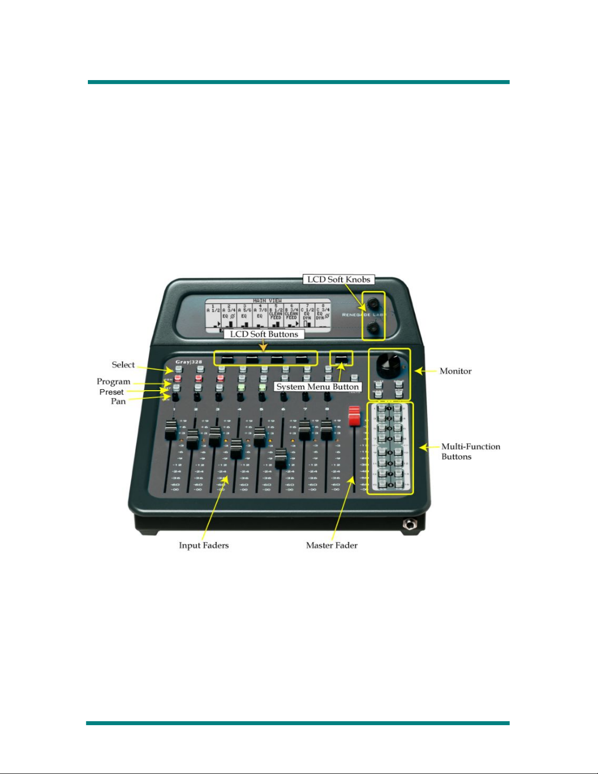
Control Panel Overview ........................................................................................ 10
The Gray|328 Control Panel Layout ...................................................................... 10
Display Controls ................................................................................................... 11
Monitor Control Section ........................................................................................ 12
utton, Pan, and Fader Rows ................................................................................ 14
Fader Strips ......................................................................................................... 15
Master Fader ....................................................................................................... 17
Multi-Function Keypad .......................................................................................... 18
CUT/TRAN buttons ................................................................................................ 19
Introducing Views and Menus .................................................................................... 21
Views vs. Menus .................................................................................................. 21
Navigating Views and Menus ................................................................................ 22
LCD Views ................................................................................................................. 24
LCD View Tree ...................................................................................................... 24
Overview .............................................................................................................. 24
Main View ............................................................................................................. 25
Route View ........................................................................................................... 28
Meter View ........................................................................................................... 29
Fader Level View .................................................................................................. 31
System Adjustments and Information Display ............................................................ 32
System Menu Tree ................................................................................................ 32
Accessing the System Menus ............................................................................... 32
Adjusting Transition and Rate ............................................................................... 33
Enable/Disable TONE ............................................................................................ 34
Selecting Reference Sync ..................................................................................... 34
Making Digital Audio Adjustments ........................................................................ 35
Adjusting Panel Setting ......................................................................................... 36
Adjusting the Headphone Output ......................................................................... 38
Displaying System Information ............................................................................. 40
Configuring Output Functionality .......................................................................... 40
View and Adjusting Module Parameters ................................................................ 45
Loudness Monitoring ............................................................................................ 50
Making Fader Assignments ....................................................................................... 53
Making Fader Input Assignments ......................................................................... 53
Setting Up Fader Output Routing ......................................................................... 56
Applying Audio Effects ............................................................................................... 59
Applying Equalization ........................................................................................... 60
Applying Dynamics .............................................................................................. 62
Overview of Dynamics Controls ........................................................................... 63
Applying Audio Delay .......................................................................................... 68
Applying Phase Reversal ...................................................................................... 70
Enabling Clean Feed ............................................................................................ 71
Adjusting Input Gain Trim .................................................................................... 73
Page 3

Renegade Labs Gray|328
Monitoring Control ..................................................................................................... 74
Monitoring Program us ....................................................................................... 74
Setting Up Solo bus Monitoring ............................................................................. 74
Monitoring Record Returns ................................................................................... 75
Setting up the Monitor Mode ................................................................................ 75
Memory Save/Recall .................................................................................................. 83
What is stored during a Memory Save .................................................................. 83
Memory Save/Recall Operations ........................................................................... 84
ESAM II Control ........................................................................................................... 87
Introduction .......................................................................................................... 87
Setting up for ESAM II Control .............................................................................. 87
Assigning Record Returns ..................................................................................... 88
Assigning ESAM II Crosspoints .............................................................................. 90
Adjusting Edit System Controls ............................................................................. 92
Locking a Fader .................................................................................................... 94
Auto To/Auto From Mode ...................................................................................... 95
ESAM II Commands .............................................................................................. 99
US Register Management (Gray 328|MXE only) ..................................................... 100
US Register Management Overview ................................................................. 100
Register Management Menu ............................................................................... 100
Transfer Registers To/From US Memory Device ................................................ 100
Deleting Registers .............................................................................................. 102
Rename or Create new US directory ................................................................ 103
US Register Directory Overview ....................................................................... 104
Software Upgrade using US Memory Device .................................................... 105
Appendix A: Installation Information ........................................................................ 106
Input/Output Configuration ................................................................................. 106
Mixer Rear Panel Detail ..................................................................................... 106
Appendix : Assigning Single Channels .................................................................... 109
Appendix C: Diagnostic Port/GPI Option ................................................................... 110
Connection ......................................................................................................... 110
Write Protect Registers ....................................................................................... 110
Pan Pot Offset Calibration ................................................................................... 111
Optional GPI Interface ........................................................................................ 111
Index ....................................................................................................................... 113
Page 4

Operator’s Guide
About this Operator’s Guide
Welcome to the Gray|328 and Gray 328|MXE digital audio mixers! The
Gray|328 and the Gray 328|MXE operations are exactly the same other
than the Gray 328|MXE includes the ability to transfer registers to and
from a USB memory device. This Operator’s Guide refers to all
operations as Gray|328 with the exception of the section pertaining to the
Gray 328|MXE memory management.
Note
For detailed installation information, for example how to add input or
output modules to your mixer, please consult the Installation Guide for
your specific mixer.
This Operator’s Guide covers the following subjects:
•Overviews
•Control Descriptions
•LCD View and Menu Descriptions
•System adjustments and Information Display
•Fader Assignments
•Applying Audio Effects
•Monitoring Control
•Memory Save/Recall
•ESAM II Control
•USB Register Management for Gray 328|MXE only.
This guide also includes an appendix containing some installation details
you may need to refer to from time to time.
About this Operator’s Guide Page 5

Renegade Labs Gray|328
Overview of the Gray|328 Mixer
Overview of the Gray|328
The Gray|328 digital audio mixer is designed for use in professional linear
video edit suites.
Note
The Gray|328 is a self-contained standalone mixer whereas the Gray
328|MXE has a separate audio engine chassis connected to a separate
Gray control panel via a Ethernet cable. All input and output functionality
is the same between the two products.
Inputs and Mixing
Optional input modules allow up to 32 audio inputs. Four slots on the
back of the mixer accept either analog (4 or 6 channel) or digital (8
channel) input modules, for a maximum of 32 channels. The mixer can
actively mix up to 6 channels of these inputs simultaneously, and send
them out over eight program output buses. Eight more program,
monitoring, or meter outputs can be added with an optional output
module.
Monitoring
The Gray|328 has eight monitor outputs and a headphone output. Any
combination of the program bus, solo bus, or record-returns can be
selected for listening on the monitor and/or headphone outputs. A built in
preview switcher provides automatic control of monitoring the program
bus and the record-returns on a channel by channel basis via edit system
control.
Loudness Monitoring
The M 6 includes the ability to monitor the loudness level of the audio
using using ITU-R BS. 770-2 gated algorithm. The Loudness Monitoring
can either follow the monitoring mode or a custom set-up can be created.
Display
An LCD display allows mixer configuration and signal characteristics to be
viewed. In addition, a unique, user-friendly system of menus and variable-
function buttons provides basic fader setup and extensive audio effects to
be applied. This system allows a great deal of functionality to be placed in
a small, space-saving console.
Feature Summary
•Accepts analog or digital audio.
Page 6 Overview of the Gray|328 Mixer

Operator’s Guide
•Digital inputs may be AES or SD/HD SDI (serial digital with embedded
audio).
•Accepts up to 32 input channels with optional input modules.
•Auto To/From allows access to all 32 input channels from the edit
system.
•Mixes 6 channels simultaneously.
•Has eight program outputs.
•Has eight highly configurable monitor and stereo headphone outputs.
•Has a built-in preview swticher.
•Loudness Monitoring using ITU-R BS. 770-2 gated algorithm.
•Optional output module can be added for additional program, monitor,
or meter outputs.
•Has powerful LCD menu system with space-saving variable-function
buttons for fader setup and applying audio effects.
About the Gray|328
The Gray|328 contains functionality that allows it to be controlled by an
edit system using the ESAM II protocol. An example of such a suite is
shown below.
Figure 1. Gray|328 in Editor-Controlled Video Edit Suite
Additional functions include the following:
•An RS422 interface for ESAM II editor control
Overview of the Gray|328 Mixer Page 7

Renegade Labs Gray|328
•Cut and transition (dissolve) capability
•Additional monitoring functions. Can monitor either program outputs,
record returns, or preview via solo mode.
•Ability to designate some inputs as record returns, independent of
faders, for monitoring the recorded mixer output.
•Full 8-bus preview functionality
•A Preset bus to designate which channels are transitioned TO during
cuts and transitions
•Auto Record handles VTR swapping from the edit system
The eight monitor outputs are controlled by a preview switcher that can
select either the mixer's program output buses or the unmodified record
return inputs for monitoring. The preview switcher also allows for a set of
inputs, configured at unity level and otherwise unmodified, to be used as
record returns that are independent of the faders. This allows fader
channels to be used entirely for mixing sources.
Under ESAM II control, a input pair is assigned an editor crosspoint
number. Each input pair can have an individual crosspoint number,
allowing for eight 2-channel sources; or multiple input pairs can be
assigned the same crosspoint number, allowing for 4-channel and/or 8-
channel source control.
Page 8 Overview of the Gray|328 Mixer

Operator’s Guide
Gray|328 Audio Block Diagram
The following diagram represents the audio flow through the Gray|328
Digital Audio Mixer.
Figure 2. Flowchart for Gray|328
Overview of the Gray|328 Mixer Page 9

Renegade Labs Gray|328
Control Descriptions
Control Panel Overview
The control panel provides access to the many features of the mixer.
Intelligent software helps cut down on the number of button presses you
need to get the job done. Buttons with multiple functions expand the
mixer’s capability.
This section provides a quick look at the control panel of the Gray|328.
The sections that follow describe the controls in more detail.
The Gray|328 Control Panel Layout
Figure 3. Gray|328 Control anel Layout
Page 10 Control Descriptions

Operator’s Guide
Display Controls
Figure 4. Display Controls
The Display Controls include the LCD display, supported by buttons and
knobs that allow you to navigate through and make selections within the
Views and Menus that appear on the display. The Views and Menus allow
you to keep track of how your mixer is set up, View characteristics of
input signals, make changes to your mixer’s setup, and apply effects to
audio (also see “Introducing Views and Menus” on page 2 ).
System Menu Button
Pressing this button brings up the System Menus on the LCD display.
System Menus are for making system-wide changes and for Viewing
certain kinds of system information (also see “Introducing Views and
Menus” on page 2 ). The Menu button is a toggle switch; pressing it
again exits the System Menus.
Soft Buttons
These four buttons are used for making selections on Views and Menus,
as shown in the example below. These are named “soft” buttons because
their functions change according which View or Menu is displayed. The
position of each corresponds to one of the virtual buttons (soft keys) in
the display.
Soft Knobs
The two rotary soft knobs (upper and lower) are used to change
parameters in many of the display menus, as shown in the example
below. These are named “soft” knobs because their functions change
according which menu is displayed.
Control Descriptions Page 11

Renegade Labs Gray|328
Monitor Control Section
Figure 5. Monitor Control Section
The Monitor controls allow you to precisely configure your monitoring
environment.
Monitor Knob
The Monitor Knob is for setting the monitor output level. Turning the knob
clockwise raises the output level; turning the knob counterclockwise
lowers the output level.
Calibration LED
The Calibration LED indicates when the monitor output level is at unity.
The Monitor Knob's reference indicator line also points at the Calibration
LED when at unity.
MUTE button
The MUTE button mutes all eight monitor outputs when pressed.
Pressing the MUTE button again un-mutes the monitor outputs. The
Monitor Mode menus displays the status of monitor output mutes. Refer
to “Setting up the Monitor Mode“ on page 75 for more information.
MODE Button
The MODE button allows you to select or set up various monitor output
matrix configurations (modes) using the Monitor Mode Menu (See
“Setting up the Monitor Mode” on page 75). The modes determine how
the eight program outputs are routed to the eight monitor outputs.
Page 12 Control Descriptions

Operator’s Guide
Note
The level of the headphone output is independent of the Monitor knob
setting or MUTE button state. See “Adjusting the Headphone Output“ on
page 38 for more information regarding the headphone output.
Gray|328 Monitor Section Block Diagram
The following diagram represents how the Gray|328 monitoring section
works with regards to the SOLO, PGM, and Record Returns.
Figure 6. Gray|328 Monitor Section Block Diagram
SOLO Button
On the Gray|328, the SOLO button functions only when the PGM OUT
button in the monitor section is inactive (not illuminated). The SOLO
button then functions as a two-way toggle, switching between solo mode
(illuminated) and Record Return monitoring (not illuminated).
•The solo mode allows you to monitor one or more fader outputs
separately from the entire mix; the Select buttons are used to select
which faders will be monitored; and the program outputs of the mixer
are not affected.
Note
The solo output routing follows fader output routing.
•Record Return monitoring (when SOLO and PGM buttons are not
illuminated) directs the inputs assigned as record returns to the
monitor outputs. The output routing follows the inputs (input pair
feeds monitor outputs & 2; input pair 2 feeds monitor outputs 3 & 4;
etc.).
Also see “Setting Up Solo bus Monitoring” on page 74.
PGM OUT Button
The PGM OUT button determines which sources provide the monitor
outputs (see the diagram above). The PGM OUT button controls all eight
channels at once. When under ESAM II control, it becomes an indicator
that lights up whenever the attached editor system is monitoring any of
the program outputs.
Control Descriptions Page 13

Renegade Labs Gray|328
When the PGM OUT button is active (lighted), the metering and monitor
outputs are from the program outputs. When the PGM OUT button is
inactive (off), monitor outputs are from either the soloed fader(s) or the
Record Return inputs, as determined by the state of the SOLO button.
Note that the monitored signals also provide the metering input for the
Meter View (see “Meter View” on page 29).
•Record Return monitoring directs the inputs assigned as record
returns to the monitor outputs. The output routing follows the inputs
(input pair feeds monitor outputs & 2; input pair 2 feeds monitor
outputs 3 & 4; etc.).
Button, Pan, and Fader Rows
Select Button Row
The Select buttons are for selecting individual faders for performing a
function, for example adding equalization to a fader’s audio. There is one
Select Button for each fader. For detail, see “Fader Strips” on page 5.
Program Button Row
The Program buttons are used to place faders’ audio on the program
output bus to which the fader has been assigned. There is one Program
button for each fader. For detail, see “Fader Strips on page 5.
The Program buttons are also used for assigning Auto From channels.
Refer to “Auto To/Auto From Mode“ on page 95 for more information
regarding Auto To/Auto From.
Preset Button Row
The Preset buttons are used to designate which fader’s audio will appear
on the program outputs at the end of a transition or cut. There is one
Preset button for each fader. For detail, see “Fader Strips” on page 5
The Preset buttons are also used for assigning Auto To channels. Refer
to “Auto To/Auto From Mode“ on page 95 for more information regarding
Auto To/Auto From.
Pan Pot Row
All fader inputs are stereo, so each fader has a pan pot to adjust the
fader’s audio signal between two assigned output channels. For detail,
see “Fader Strips” on page 5.
Faders Row
There are eight stereo faders for adjusting audio gain. The faders are
numbered through 8 beginning from the left. For detail, see “Fader
Strips on page 5.
Page 14 Control Descriptions

Operator’s Guide
Fader Strips
A fader strip comprises a fader, a unity LED, a Pan Pot, a Preset button,
a Program button, and a Select button.
Figure 7. Fader Strips
Fader
The fader adjusts the output audio level of its stereo inputs. The fader
can adjust the output level from +9dB to -∞. Each fader is assignable to
any input, can be routed to any of the Program outputs, and can be
panned between its two audio channels. The signal through the faders
can be compressed/expanded, equalized, delayed, phase reversed, gain
trimmed, or set to a clean feed (unmodified) for dubbing purposes.
Unity LED
The Unity LED lights up when the fader is set at unity gain.
During Memory Recalls, the Unity LED has these functions:
Control Descriptions Page 15

Renegade Labs Gray|328
•The Unity LED is red when the physical position does not match the
audio position.
•The Unity LED is yellow when the audio level is at unity.
•The Unity LED is off when the physical position matches the audio
position and the audio level is not at unity.
Pan Pot
The pan pot allows you to adjust the fader’s audio output between the
odd and even output buses. Because any input can be routed to any of
the eight output buses, the behavior this seemingly simple pan can be
complicated.
As an example, consider the usual case where output bus is the left
monitor output and output bus 2 is the right monitor output. Suppose the
left input is routed to output bus only, and the right input is selected on
bus 2 only. Turning the pan knob fully counterclockwise would yield only
left input audio from the left speaker. With the pan knob fully clockwise,
we would hear only right input audio from the right speaker.
However, if you route the left input channel of the fader to output bus 2
and the right input channel to output bus , the pan pot may behave
differently than you expect. Turning the pan knob fully counterclockwise
yields the right input channel only in the left speaker. This is due to the
right input channel being routed to the odd numbered output channel.
Since the pan knob works based on the assigned output channels,
whichever source is routed to the odd output channels is what is heard.
Turning the pan knob fully clockwise yields the left input channel only in
the right speaker. This is due to the left input channel being routed to the
even numbered output channel. Since the pan knob works based on the
assigned output channels, whichever source is routed to the even output
channels is what is heard.
Preset Button
The Preset button is a toggle on/off switch used to set up the fader’s
audio to appear on the program outputs at the end of a transition or cut.
When the Preset button of a fader is lighted, its audio will appear on the
program outputs at the end of the transition or cut.
Transitions and cuts are set up using the RATE/TRANS Menu. See
“Adjusting Transition and Rate” on page 33.
Program Button
The Program button places the fader’s output onto the program bus. The
specific program outputs on which the fader’s channels will appear is
determined by the output routing for the fader. See “Setting Up Fader
Output Routing “on page 56.
The Program button is toggle on/off. The Program button indicates that its
associated fader is on the Program bus by lighting up.
Page 16 Control Descriptions

Operator’s Guide
Select Button
The Select button has various functions with regard to its associated
fader, for example:
•Selecting the fader for certain operations, for example applying audio
effects.
•Bringing up menus for making changes to the fader’s audio input
signals.
If no input is assigned to the fader, pressing the Select button
brings up the Input Assignment Menu on the display.
If the fader has inputs assigned to it, the Select button accesses
the various menus, with the Route Menu as the default menu.
The Select button is a toggle on/off. When the Select button is active, it is
illuminated.
Note
Deselecting the Select button in a menu sequence often is equivalent to
pressing the enter key on a pc. It can cause changes to be accepted.
Master Fader
The Master Fader is used for adjusting the overall gain of all eight
Program outputs. The gain settings of individual faders are not affected
by the Master Fader.
Figure 8. Master Fader
The Master Fader range is from 0dB (unity) to -∞. The Master Fader has
no unity LED, since bringing the fader all the way to the top of its travel is
unity.
Control Descriptions Page 17

Renegade Labs Gray|328
When the master fader is set to 0dB (the top of its travel), the program
output audio will be at unity gain with respect to the levels from individual
faders.
When the Master Fader is brought down, the program output gain will be
reduced by the amount of fader attenuation. The individual faders’
respective gain settings will follow. In other words, if fader # is set to
+6dB and the Master Fader is set to -3dB, fader # ’s actual output level
will be +3dB.
Note
The Maser Fader will not effect faders that are set to Clean Feed Mode.
See “Enabling Clean Feed“ on page 7 for more information.
Multi-Function Keypad
Figure 9. Multi-Function Keypad
The Multi-Function Keypad is a set of buttons that is available for use in
many operations. Here are some examples:
•Headphone output bus routing
•Fader input assignment
•Program output routing
•Monitor routing and configuration
•Memory save/recall
The Multi-Function Keypad provides a means for making selections and
for indicating the presence of audio on specific channels.
Page 18 Control Descriptions

Operator’s Guide
The Multi-Function Keypad is laid out to correspond with the input module
slots, labeled A, B, C, and D on the rear panel of the mixer. Small buttons
that light represent the possible stereo channels ( /2, 3/4, etc.)
In addition, the keypad is numbered down its middle with numerals
through 8, for using the keypad to indicate or select program outputs.
Figure 10. Multi-Function Keypad Layout
The Multi-Function keypad may be used in conjunction with the Select
buttons to indicate (or designate) which audio channels are applied to a
fader. When the Select button for an individual fader is pressed, the audio
assigned to it will be indicated on the Multi-Function keypad. The system
menus must be closed for this to occur.
Note
In some applications, the Multi-Function Keypad may be used differently
than described above. Such uses will be described in the related
procedures.
CUT/TRA buttons
The CUT and TRAN buttons initiate cuts and transitions, which are
synchronized to video frames. The rates of transition, and which buses
are involved in cuts and transitions, are set using the RATE/TRAN Menu
(see “Adjusting Transition and Rate on page 33).
Control Descriptions Page 19

Renegade Labs Gray|328
CUT Button
The CUT button cuts (using a ½ frame dissolve) any audio on the
Program bus to any audio that is on the Preset bus. The Program and
Preset button lamps on the fader(s) involved will toggle from one bus to
the other to indicate when the cut has occurred (unless both the Program
and Preset bus are on at the same time in which case both lamps remain
lit).
TRA Button
The TRAN button transitions any audio on the Program bus to any audio
that is on the Preset bus. The Program and Preset buttons will toggle
from one bus to the other indicating the transition has occurred (unless
both the Program and Preset bus are on at the same time in which case
both lamps remain lit). When a transition is active, the TRAN button will
be illuminated. If, during a transition the CUT button is pressed, the
transition will end immediately and a cut will proceed.
Note
The transition rate you select applies only to transitions. Cuts always do a
/2 video frame dissolve.
Selecting both Program and Preset buttons on the same fader allows the
associated audio to remain unmodified on the Program bus during
transitions or cuts.
Page 20 Control Descriptions
This manual suits for next models
1
Table of contents