ARC Audio PS8 Datasheet

PS8
PS8
Installation &
Installation &
Quick Start Guide
Quick Start Guide
WWW.ARCAUDIO.COM
Pending the completion of the full PS8
Software and installation manual we have
created this temporary quick start manual
covering a portion of the topics most
commonly asked by users and dealers.
(THIS IS NOT THE COMPLETE MANUAL)

ARC AUDIO
1. COVER PAGE
2. INDEX
3. INTRODUCTION TO THE PS8
4. PACKAGING CONTENTS
5. PS8 INSTALLATION AND COMPONENT DESCRIPTION
5.1 Mounting considerations
5.2 Dimensions
5.2.1 External Dimensions
5.2.2 Mounting Dimensions
5.3 PS8 Hardware Components
5.3.1 Cosmetic top cover
5.3.2 Cosmetic top cover under panel
5.3.3 PS8 Main PCB
5.3.4 PS8 Main Chassis Housing (Upper and Lower)
5.3.5 PS8 activity and status display
5.3.5.1 Illuminated ARC Audio & PS8 Logo
5.3.5.2 Digital input conrmation indicator
5.3.5.3 USB connection conrmation indicator
5.3.5.4 Bluetooth connection conrmation indicator
5.3.5.5 PS8 signal clip indicator
5.3.5.6 PS8 User prole lead use indicator
6. CONNECTION YOUR PS8
6.1 Analog signal inputs (RCA)
6.1.1 Low Level RCA Inputs
6.1.2 Dierential input RCA/Speaker level switch
6.1.3 Hi Level Speaker Input
6.1.4 PS8 Speaker autosense turn on/o jumper
6.2 User interface connections
6.2.1 PSC remote display connection
6.2.2 USB Connection
6.3 Main Power Terminal Connections
6.3.1 Signal Ground Connection
6.3.2 Illumination trigger lead
6.3.3 User prole 2 trigger
6.3.4 User prole 1 trigger
6.3.5 Remote Turn on - Output connection
6.3.6 Remote Turn on - Input connection
6.3.7 +12V Positive battery connection
6.3.8 Chassis ground connection
6.4 Digital inputs & sources
6.41 Coaxial input
6.4.2 Optical Input
6.4.3 Bluetooth Streaming Input
6.5 Other signal inputs
6.5.1 3.5mm Unbalanced Aux input

ARC AUDIO
6.6 RCA Signal Outputs
6.6.1 RCA PRE OUT - Signal Outputs
7. PS8 SOFTWARE IINSTALLATION AND REMOVAL
7.1 PS8 Software interface installation general comments and overview
7.2 System requirements
7.3 .NET driver installation
7.4 Software installation
7.4.1 Windows 7 installation guide
7.4.2 Troubleshooting section for software installation
7.5 Uninstallation and removal of the software
7.5.1 PS8 software uninstall general comments and overview
7.6 Updating the PS8 user software
8. UPDATING THE PS8'S FIRMWARE
8.1 Updating the PS8’s operating rmware
9. CONNECTING THE PS8 TO YOUR PC
9.1 PS8 USB failsafe protocol
9.2 Connecting the USB to your PC and the PS8
9.3 “...” Ellipsis check box
9.4 Send preset 1 to PS8
9.5 Send preset 2 to PS8
9.6 Send preset 3 to PS8
9.7 Send all presets
9.8 Retrieve Preset 1 from PS8
9.9 Retrieve Preset 2 from PS8
9.10 Retrieve Preset 3 from PS8
9.10 Work Oine
10. OTHER PS8 FEATURES, USER DEFINED FEATURES AND MORE
10.1 User dened channel names and assignments
10.1.1 Outputs
10.1.2 Channel naming boxes
10.1.3 Channel assignments
10.2 Remote output turn on/o delay user panel
10.2.1 Remote turn on lead (On) delay user control
10.2.1.1 Turn on delay slider
10.2.1.2 Turn on display readout
10.2.2 Remote turn on lead (O) delay user control
10.2.2.1 Turn o delay slider
10.2.2.2 Turn o display readout
10.3 User preferences
10.3.1 Show temperature in Celsius
10.3.2 Enable Tool Tips
10.3.3 Invert Illumination Trigger
10.4 PS8 password utility and setup
10.4.1 PS8 Password entry for syncing “Password Entry”
10.4.2 Setting a new password“New Password”
10.4.3 Show password
10.4.4 “Set” password
10.4.5 “Clear” reset system
10.4.6 “Cancel” button
10.4.7 “Just set PC password”Password button
10.5 Advanced user more selection
10.6 Export setting les to CSV
10.7 Set frequency range linits panel
11. USER SOFTWARE GRAPHIC FEATURE OVERVIEW
11.1 Top Header “File”
11.1.1 Open Settings
11.1.2 Save Settings As
11.1.3 Save Settings
11.1.4 Recent Files Button
11.1.5 Import Preset
11.1.6 Export Preset
11.1.7 Export Files to CVS
11.1.8 Exit

ARC AUDIO
11.2 “Sync”
11.3 “Presets”
11.31 Preset catagory 1
11.32 Preset catagory 2
11.33 Preset catagory 3
11.34 How presets work
11.35 How to save and sync all three presets
11.36 Retrieving and Syncing from the PS8
11.4 “Setup”
11.4.1 User input/output channel assignment panel
11.42 Remote turn on/o program panel
11.43 Password denations, setup and system panel
11.44 Bluetooth user interface and setup panel
11.45 User preference setup panel
11.46 Advanced user mode toggle switch
11.5 “Meters”
11.5.1 Signal Input
11.5.2 DSP Output
11.5.3 Signal Output
11.5.4 Foreground
11.6 “Help”
11.6.1 About
11.6.2 Check for new PS8 rmware
11.6.3 Check for new remote rmware
11.6.4 Download user manual
11.6.5 Open User manual
12. ACTIVE SOFTWARE PANEL HEADER AND FUNCTION OVERVIEW
12.1 Input
12.2 Router (Standard Mode)
12.2.1 Input channel assigned name display
12.2.2 Input/Output signal router assignment check box (Standard Mode)
12.2.2.1 Output channel assigned display

ARC AUDIO
12.3 Mixer Panel (Advanced Mode)
12.3.1 Input channels and invert input polarity
12.3.2 Input/Output channel intersection variable level conrols
12.3.3 Input/Output channel intersection level display box
12.3.4 Input/Output channel intersection summing button
12.3.5 Output channels 1-8 invert polarity boxes
12.3.6
12.4 Crossover Control Panel
12.4.1 Channels 1-8 crossover lter type window
12.4.2 Channels assigned name display
12.4.3 Channel crossover type check boxes
12.4.4 High Pass crossover lter type adjustment window
12.4.4.1 HP crossover slope selection window
12.4.4.2 HP crossover frequency selection controls
12.4.4.3 HP crossover damping selecton window
12.4.4.4 HP crossover “variable ”Q” adjustment control
12.4.4.5 HP crossover Bessel normalization controls
12.4.5 Low Pass crossover lter type adjustment window
12.4.5.1 LP crossover slope selection window
12.4.5.2 LP crossover frequency selection controls
12.4.5.3 LP crossover damping selection window
12.4.5.4 LP crossover variable “Q” adjustment control
12.4.5.5 LP crossover Bessel normalization controls
12.5 Signal Delay / Channel 1-8 Invert Polarity Control Panel
12.5.1 Channel 1-8 signal delay adjustment utility window
12.5.1.1 Channel assigned name display
12.5.1.2 Channel link/unlink buttons
12.5.1.3 Channel signal delay adjustment slider
12.5.1.4 Channel signal delay adjustment value
12.5.2 Channel 1-8 output invert signal polarity utility window
12.6 EQ Control Panel
12.6.1 Equalization channel selection panel
12.6.2 EQ channel selection check boxes
12.6.3 EQ channel assigned name display
12.6.4 EQ channel frequency value readout display
12.6.5 EQ channel selection, All channels check/uncheck
12.6.6 EQ plot channel selection check boxes
12.6.7 EQ plot selection all channels check/uncheck
12.6.8 Parametric EQ mode selection
12.6.9 1/3rd Octave eq mode selection
ARC AUDIO
12.6.10 Equalization adjustment and controls
12.6.10.1 Individual frequency adjustment slider and bar
12.6.10.2 Individual frequency adjustment ne adjustment buttons
12.6.10.3 Individual band frequency center readout display
12.6.10.4 1/3rd Octave EQ mode “All Flat” Button
12.6.10.5 1/3rd Octave EQ mode “All 1/3rd Octave” reset button
12.6.10.6 Parametric EQ band ne tuning controls
12.6.10.7 All 1/3rd Octave reset button
12.6.10.8 Parametric EQ band, variable frequency selection slider
12.6.10.9 Parametric EQ band variavle frequency value display
12.6.10.10 All “Q’s” reset button
12.6.10.11 Parametric EQ band variable “Q” slider
12.6.10.12 Parametric EQ band variable “Q” value display
12.6.10.13 EQ frequency plotting chart dispaly
12.7 Signal output control panel
12.7.1 Master volume control
12.7.2 Output channels 1-8 signal trim control
12.7.3 Channel trim level value readout display
12.7.4 Output channel trim adjustment slider
12.7.5 Channel trim all channels link/unlink button (Tandem)
12.7.6 Output fader controls
12.7.7 Output fader level value readout display
12.7.8 Output fader adjustment slider
12.7.9 Channel name and assigned faders panel access button
13.0) Master Volume Output Control
13.1 Master volume control
13.2 Master volumecontrol indicator
14.0) Bottom Header User Sotware Graphic Feature Overview
14.1 Output channel muting
14.2 Electronic serial number display verication
14.3 Preset selection buton and status indicator
14.3.1 Software position preset status selection and status button
14.3.2 PS8 hardware physical position preset selection and status button
14.4 Oine mode seleciton box
14.5 Phase lock
14.6 Digital Indicator
14.7 USB connection indicator
14.8 System voltage display
14.9 PS8 Internal DSP core temperature
15.0) Replacing/Upgrading The PS8’s Output Devices

ARC AUDIO
16.0) Trouble Shooting Guide
16.1 System turn on/o pop
16.2 PS8 not turning on
16.3 No output from Ps8
16.4 PS8 controls not responding smoothly or settings dont appear
accurate when adjusting.
16.5 When using EQ panel there are no sliders on the adjustment screen
16.6 Cannot retrieve settings from PS8
16.7 USB conrmation light on software not ashing
16.8 Temperature reading is displaying Celcius and not Farenheit
16.9 Firmware update failed
16.10 Loss of “AUX” indicator during rmware update
16.11 USB light does not ash and controls do not respond after rmware update
16.12 PS8 turns on and then shuts o 2 seconds later and continues
“looping”.
16.13 After sending a setting le from the PC to the PS8 the other presets do not
properly reect what the software is displaying on the other presets.
16.14 After installing/updating the PS8 software onto the PS8 there is no PS8
Software Icon on my desktop or favorites menu.
16.15 When using analog or digital inputs in conjunction with a remote turn on
input trigger, upon rst re up and start the PS8 makes a digital noise and
sometimes does not start up properly.
16.16 The PS8 takes an excessive amount of time to turn on.
16.17 The PS8 takes an excessive amount of time to turn o or will not turn o.

3. Welcome to the PS8
Welcome to the ARC Audio family of performance signal processors and thank you for your purchase of
the ARC Audio PS8 car audio digital sound processor. The PS8 is the most advanced car audio processor
on the market placing the focus of its entire development on placing the power of tuning back into the
hands of the user and the listener. The unit is a unique combination of the highest quality analog and
digital components available giving all levels of user and/or enthusiast the nest product available
whether you are a competitor or simply enjoy music being reproduced as it was intended.
Developed exclusively for ARC Audio by Robert Ze, Richard Greenway, Brent Waddell, Fred Lynch and
Brad Ott, the ARC Audio PS8 features leading edge technology and design oering listeners in real time
the most transparent and dynamic sound possible of any processor available to the 12 volt market today.
Using the hands on experience and knowledge of the championship ARC Audio sound quality competi-
tion team with most every audio processor designed since the early 90's, the PS8's user interface oers
multiple levels of operation giving all users from the most experienced professionals to every day enthu-
siast's just getting started, the most in-depth and easy to use tuning capability of any digital sound pro-
cessor on the market.
The ARC Audio PS8 gold plated audiophile designed main PCB uses a specically designed audio grade
32-bit DSP main processor optimized for operation at 192 kHz and 170mHz operating speed with Dual
72-bit algorithmic volume control processors, eliminating signal compression as volume is increased,
giving the PS8 the most transparent, dynamic and musical signal processing capability of any processor
on the market. In addition, the main DSP in the PS8 uses 32-bit DA/AD converters capable of operating at
192 kHz and a multi channel DSD direct stream digital input, increasing the exibility of applications and
input types available without any compromise to the sound quality of the end product.
Oering 6 channels of fully dierential analog inputs for RCA (Low Level) or Speaker (Hi Level ) operation
with summing capability, Optical and Digital Coaxial inputs, and optional 3.5mm unbalanced accessory,
input the PS8 gives users the ability to customize their own personal listening experience in most any
variation of aftermarket or OEM application.
Leaving no stone unturned, the PS8's PC based user interface oers users the largest and most extensive,
highest resolution selection of user dened tuning features available in any car audio processor on the
market. Features include phase correct crossovers with selectable LP/HP/BP/AP on all 8 output channels,
including Linkwitz-Riley, Butterworth, Variable "Q", and Bessel damping options, 1,998,000 precision
selectable crossover points and 6/12/18/24/30/36/42/48 dierential capable slopes on each of the PS8's
output channels. Other features include linkable .01ms resolution signal delay, input and output phase
invert control, an almost unlimited variation I/O signal mixer, precision signal input and output level
controls and an industry rst, user dened 8 channels of 31bands per channel 1/3rd octave or 31bands
per channel of fully customizable parametric equalization with single channel and multi channel
"Global" capability, with over 2,284,996,608,000,000 user dened variations at your nger tips.

4. PS8 PACKAGE CONTENTS
(1) ARC Audio PS8 digital sound processor
(6) RCA to speaker lead pigtail adapters
(1) 6.0" USB Interface A to B Cable
(1) Printed PS8 user advisory notice
(1) Printed ARC Audio PS8 warranty policy
(1) Printed PS8 Software quick start notice
5) PS8 INSTALLATION AND COMPONENT DESCRIPTION
5.1 Mounting Considerations
The ARC Audio PS8 digital sound processor is designed for easy and exible installation into your vehicle. To
ensure proper operation and long term reliability of your new purchase, please follow the suggestions
below.
1. The PS8 digital sound processor needs to be installed in the signal path between your signal source and
your external amplier(s).
2. The PS8 digital sound processor must be mounted to a solid surface. Please select a dry clean location in
the trunk or passenger compartment only. Do not mount the PS8 to any area that may experience excess
vibration. Position the PS8 processor in a location that will allow for sucient air ow with considerations
made for future access and ease of service.
Warning,
Please check the suitability of the installation location before you begin. Do not cut any of the car's structure. Pay
close attention to what is behind the panels or carpet you are mounting to. Often manufactures will hide wires, com-
puters or other electronic devices in the exact areas you will wish to do your install.
When mounting the PS8 to the oor of the vehicle, be sure to inspect underneath the vehicle to prevent damage to the
vehicles fuel delivery system or factory wiring, so as to prevent serious damage or hazardous conditions on your
vehicle
If you do not have experience with automotive electrical and mechanical systems, contact a professional installer.
Paying a qualied installer is almost always cheaper than paying a dealership to repair your car.
x6
x1
x1
GND
+12V
REMOTE - INPUT
REMOTE - OUTPUT
PROFILE 1
PROFILE 2
ILLUMINATION
SIGNAL GROUND
ANALOG
INPUT
RCA
SPEAKER
INPUT LEVEL
+9 - +15v
USB DISPLAY CH6 CH5 CH4 CH3 CH2 CH1
DC IN
ADVANCED DIGITAL SOUND PROCESSOR
DIGITAL
INPUT
CH 1/2
AUX IN
CH 5/6
CH1 CH2 CH3 CH4 CH5 CH6 CH7 CH8
OUTPUT
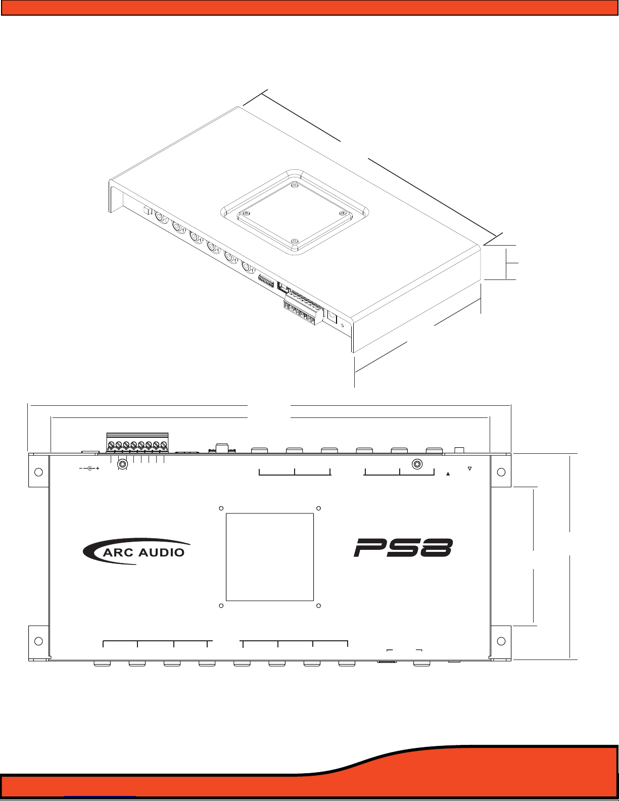
250mm
130mm
30mm
222mm
106mm
70mm
245mm
5.2- PS8 Dimensions
ARC Audio PS8: External Dimensions
ARC Audio PS8: Mounting Dimensions

5.3 PS8 Hardware Components
5.3.1 - PS8 Cosmetic top cover
The cosmetic top cover of the PS8 is a 2 piece decorative
assembly that covers the main housing connections and
installation mounting points. To install the cover, care
fully place the extrusion over the top of the main
housing until it is resting at on the top surface. (This
cover is held in place in conjunction with the PS8 activity
and status display and its associated hardware). (The
inner decorative panel is removable for painting or
alternative nishing by turning over the top cover and
removing the Four (4) 2.5mm Phillips head screws from
the plate. When reinstalling the under plate, make sure
to thread the screws manually to prevent the screws
from stripping.)
5.3.2 - Cosmetic top cover under panel
The cospetic top cover under panel is screwed to the
under side of the PS8 main cover. This panel is remov-
able as it may be painted, powder coated etc to match
the installation or vehicle theme.
5.3.3 - PS8 main PCB
The PS8 main PCB is home for all of the electronics of the
PS8. The main PCB if for some reason needs to be
removed please be sure to practice safe handling
instructions.
Be sure to discharge yourself by grabbing ahold of the
PC8’s RCA barrel connectors rst. Then remove the four
screws and then carefully place the PCB into an antistatic
bag.
5.3.4 - PS8 Main Housing (Upper and Lower)
The main housing of the PS8 is comprised of a 2
piece stamped steel chassis that holds the main circuit
board of the PS8. The main chassis is labeled with all
wire connection labeling and also includes the incorpo
rated mounting tabs for installation of the PS8 into your
individual application.

5.3.5 - PS8 Activity and status display
The PS8 activity display gives users visual tools on the
face of the main display unit allowing them, in real time,
to see the current status of the PS8 and its dierent user
interface based components. The display oers users a
general overview of the interface features and their
current mode of operation.
• Illuminated ARC Audio & PS8 logo - The logos are a
dual operation illuminated display showing users when
the PS8 is powered on or o.
• Digital Input Indicator- This single (Blue) LED, when lit,
indicates when the PS8 is actively receiving digital
signal from a digital source such as optical, digital
coaxial, or Bluetooth (When the Bluetooth accessory
module is in use)
• USB Connection indicator- This single (Blue) LED,
when lit, lets users know when the PS8 is actively
connected to a PC and the user interface is communi
cating with the processor.
• Bluetooth Connection Indicator- This single (Blue)
LED, when lit, lets users know when the PS8 is actively
receiving signal from a linked Bluetooth compatible
device.
• Signal Clip Indicator- This single (Red) LED, when lit or
ashing, lets users know when the processor is sensing
any clipped signal at any part of the signal chain within
the PS8
• PS8 User Prole Lead Indicator- This single (Blue) LED,
when lit, indicates that the PS8 is currently being
triggered into one of its three onboard user dened
presets thru one of the 2 onboard ground triggered
prole leads.
5.3.5.1- Connecting the status display
When installing the PS8 status display carefully
connect the plug dongle into the 8 pin recep-
tacle on the main circuit boards of the PS8. The
receptacle is visible thru the top opening of the
PS8 with the status display removed
(See diagram 5.1). Be careful to note the guide
orientation that indicates the proper direction to
install the plug. DO NOT FORCE THE PLUG INTO
THE SOCKET!
Ps8
DIGITAL
USB CLIP
USER
Diagram 5.1

RCA
SPEAKER
INPUT LEVEL
CH1 CH2 CH3 CH4 CH5 CH6 DISPLAY USB
+12V
GND
REM - IN
REM - OUT
P - 1
P - 2
ILLUM
SIG GND -
Dierential Low/High
(Speaker Level) Inputs
Diagram 6.1
6) CONNECTIONS TO YOUR PS8
6.1 - Analog Signal Inputs (RCA)
6.1.1- PRE IN Low level primary analog Inputs (RCA)
Channels 1,2,3,4,5,6 Inputs - Connect here your RCA signal input leads coming from your
analog source. Each connection is capable of receiving signal levels up to 8 Volts RMS.
(See diagram 6.1)
6.1.2- Dierential input RCA/Speaker level switch
This switch allows users to change the operation of the RCA inputs of the PS8 between Low-
Level RCA and Speaker Hi-Level operation. (See diagram 6.2)
6.1.3- Hi Level Speaker inputs
Channels 1,2,3,4,5,6 Inputs - Connect your vehicles factory speaker leads to the RCA inputs of
the PS8 using the provided RCA to speaker lead pigtail adapters. Each input connection, when
in Hi level mode, is capable of receiving HI-Level signals from 1.5V - 20.0V input from any OEM
factory stereo system (See diagram 6.1)
Warning- If using the PS8 as a signal summing device, make sure to verify the signal from
your OEM system with an Oscilloscope and multi meter prior to making your nal connections .
RCA
SPEAKER
INPUT LEVEL
CH1
Diagram 6.2
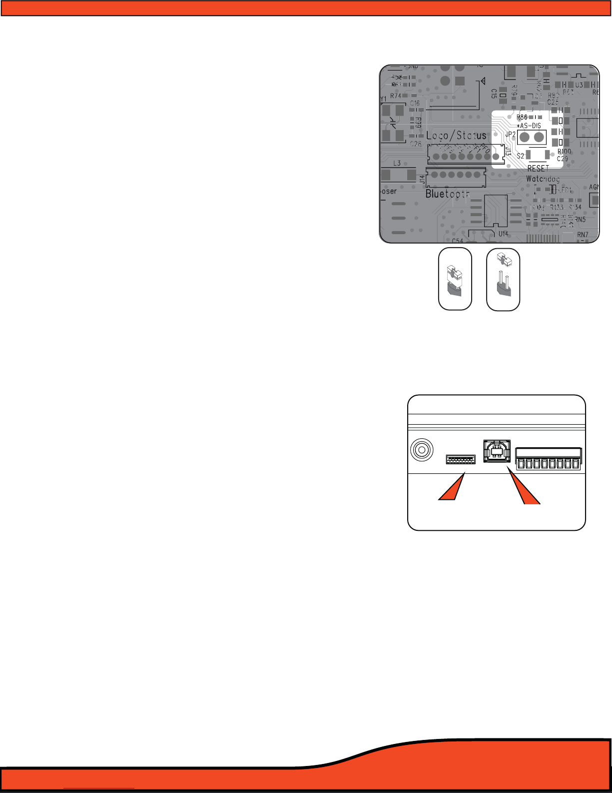
Diagram 6.3
DISPLAY USB
+12V
GND
REM - IN
REM - OUT
P - 1
P - 2
ILLUM
SIG GND -
PSC Display
Connection USB/PC Connection
Diagram 6.4
Disabled Enabled
Auto Sense
6.1.4 - PS8 Speaker Autosense turn on/o jumper
The ARC Audio PS8 has a patented bridged mode
detection circuit incorporated into the design, improving
the exibility of the PS8 for OEM integration applications.
This mode can detect the BTL (CHIP) used in most head
units and stock ampliers. When turned on, Bridged
mode detection will sense this chip and turn on the PS8.
BTL Auto detect is activated by removing the PS8's status
display and changing the jumper location as indicated.
(See diagram 6.3)
Please note that BTL Auto detection will not work on all
vehicles and some vehicle may require the remote turn-on
lead input to be connected to the vehicles accessory
circuit.
6.2 - User Interface Connections-
6.2.1 - PSC display cable connection
This connection is for the PS8's optional accessory
controller (ARC Audio PSC). This connection is only
compatible with the PSC's proprietary interconnect cable,
and is only compatible with the ARC Audio PSC Controller
(Sold Separately). (See diagram 6.4)
6.2.2 - USB Connection
This port is used to connect your computer to the PS8 via
the provided USB A TO B cable. This connection is
required for the PS8's user utility software to
communicate with the PS8 and adjust its onboard DSP
functions. The PS8's USB interface is USB 1.1/2.0
compatible.
(See diagram 6.4)

6.3 - Main Power Terminal Plug Connections
6.3.1 - Signal Ground
This lead allows users to use the PS8 in an OEM application for increased compatibility to factory
radios using a variety of balanced and common ground applications.
6.3.2 - Illumination
If using the ARC Audio PSC controller (Sold Separately), this lead allows users to interface with the
vehicles parking light circuit to trigger the onboard controller illumination circuit . This
function is user denable for the type of convenient trigger that is available in reference to the
location of the PS8's installation.
6.3.3 - Prole 2
Using a 3 position latching toggle switch, connect
this lead to ground to switch the PS8 to its P3 user
dened preset without the need of a laptop or
controller
(See diagram 6.5)
6.3.4 -Prole 1
Using a 3 position latching toggle switch, connect
this lead to ground to switch the PS8 to its P2 user
dened preset without the need of a laptop or
controller
(See diagram 6.5)
6.3.5- Remote Output
This lead output is used to activate and control the remote turn on of additional devices including
ampliers, relays etc.
(See diagram 6.5)
TAKE SPECIAL NOTE- The PS8's remote output current capacity is rated at 250mA. This voltage out is capable
of driving several ARC Audio ampliers without the need of a relay. If you are using ampliers other than ARC
Audio, and they do not use an ultra low current microprocessor-triggered turn on circuit, we recommend
using a quality low current relay for this operation. Please be sure that the relay trigger requirement does not
exceed the 250mA rating.
WARNING- When using the PS8 in your vehicle’s system, you must trigger all of your system’s ampliers o of
the PS8's Remote Turn- on output circuit. The remote output lead timing is controlled and customizable thru
the setup function of the user utility, allowing the user to control the exact timing on and o requirements for
their particular application, reducing, if not eliminating, the possibility of turn on/o pops and other
unwanted related noises, preventing possible damage to your system’s components.
USB
+12V
GND
REM - IN
REM - OUT
P - 1
P - 2
ILLUM
SIG GND -
Diagram 6.5

6.3.6- Remote Input
Connect any triggered +12V signal
remote turn on lead for aftermarket
systems, +12V switched vehicle acces-
sory lead (on not autosense compat-
ible applications,) to turn on and
activate the PS8 and all of its functions
(See diagram 6.6)
6.3.7- +12V Input
+12V Positive fused connection to the
vehicle’s battery or constant power
source. (Fuse rating should be no
higher than 5 amps) (See diagram 6.6)
6.3.8- Ground
Connect this lead to the vehicle’s
chassis or any clean grounding point.
The grounding point should be clean,
free of paint, grease, debris, etc., and
on bare metal. It is not recommended
to connect any ground wire of any
audio component to seat or seatbelt
bolts or hardware.
6.3.9 - DC Input Jack
By using an AC/DC wall plug adapter (not Included), the PS8 can be used in home or studio
applications. If you wish to use this feature of the PS8, please make sure to purchase a wall adapter
from a local electronics parts store with the following parameters. To operate this feature you will
be required to jumper a wire lead between the main power plug’s 12V and Remote turn on input
lead connection
(See section 6.3). If you power supply is not switched output operation you may
wish to connect a switch inline so you may turn the PS8 on and o.
Voltage rating +9V - +15V (Tip Positive)
Current Capacity - Minimum 2 Amps
Plug dimensions - 2.1mm I.D. x 5.5mm O.D.
6.4 - PS8 Digital Inputs & Sources
The PS8's digital platform is capable of receiving a variety of digital signals.
Please note that if you choose to run any of the PS8's digital signal inputs, you will be required to
use the PSC controller (sold separately) in order to have control of the system’s volume.
3 X 30 AMP MAX
ARC Audio Inc., USA
+12VGND
TURN
ON
3 X 30 AMP MAX
ARC Audio Inc., USA
+12VGND
TURN
ON
Diagram 6.6
+12V
GND
REM - IN
REM - OUT
P - 1
P - 2
ILLUM
SIG GND -
DC Input Jack Diagram 6.7
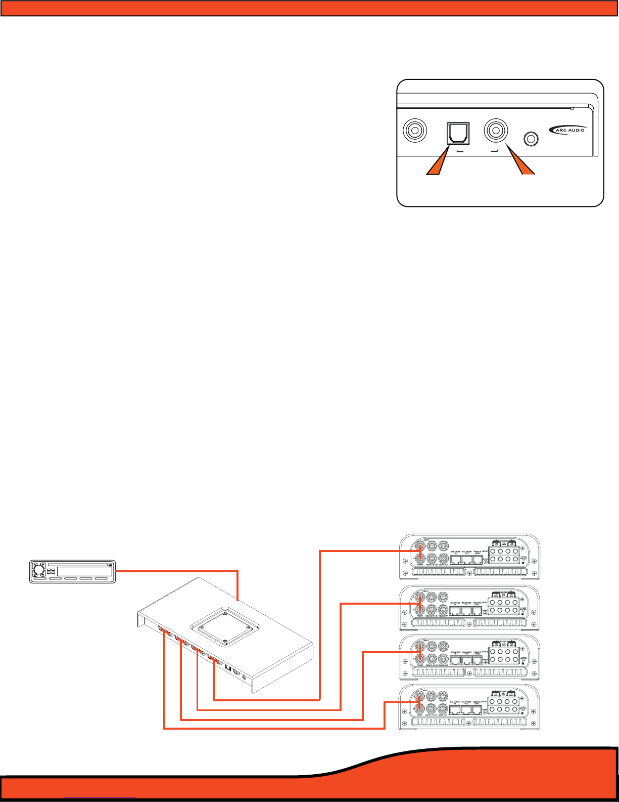
6.4.1 - Digital Input (Coaxial)
Connect any 75 ohm shielded cable to this location
with any compatible digital signal of 48kHz/24-32bit
max, stereo signal, for optimum performance and
signal benet of this input. (See diagram 6.8)
6.4.2 - Digital Input (Optical)
Connect any TOSLINK terminated optical ber cable to
this location with any compatible digital signal of
48kHz/24-32bit max, stereo signal, for optimum perfor
mance and signal benet of this input.
(See diagram 6.8)
6.4.3 - Bluetooth streaming input
The PS8's streaming audio Bluetooth capability requires the use of the ARC Audio PS8-BTM
accessory Bluetooth module (sold separately). The BTM supports the latest Bluetooth 2.1 + EDR
standard formats found on most of today's streaming Bluetooth capable devices.
6.5 - Other signal inputs
6.5.1 - 3.5mm Unbalanced Aux input
Connect to this location any unbalanced signal source device such as a hardwired MP3, iPod,
navigation system, Etc. This input is selectable thru the user utility and upon activation, removes
the PS8's Channel 5&6 RCA input from the available input sources while in this user operation.
6.6 - PS8 RCA signal outputs
6.6.1 - Channels 1,2,3,4,5,6,7,8 outputs.
Connect your system’s RCA interconnect cables from these locations to your systems ampliers.
The RCA outputs are unbalanced and not a balanced onput. (See diagram 6.9)
Diagram 6.9
CH8 DIGITAL IN
AUX IN
Diagram 6.8
Optical input Coaxial input

7) PS8 SOFTWARE AND INSTALLATION AND REMOVAL
7.1- PS8 Software Installation and Removal General Comments
The PS8 software and user utility is designed to give you full access to the complete power and feature set of
the ARC Audio PS8. Installation can be completed in a matter of minutes for most users and is compatible
with an extremely wide and diverse selection of laptop computers and operating systems.
7.2- System Requirements
• The PS8 user interface and adjustment software requires a PC with a genuine version of Windows XP,
Windows Vista, Windows 7 and Windows 8 operating system already installed. (NOTE: The PS8 software is
not compatible with Windows 8 RT Tablet operating system as the USB protocol is not compatible with the
Microsoft .Net Framework protocol that the PS8 software operates on.)
• PC hardware restrictions also require that your PC be equipped with a processor with a minimum 1 GHz
minimum processor speed (Minimum recommended) and minimum 512 MB Ram in order to install and
operate the software without possible issues.
• Unlike other processor software the PS8 software utility will automatically update your computer with the
required USB compatibility drivers allowing for a smooth installation process without the need of additional
and time tasking procedures to complete this process.
NOTE- It is recommended that your PC be up to date with all software and hardware driver updates prior to installa-
tion of this software to ensure correct installation and operation of this software. These updates should include all
Windows, USB driver and hardware driver updates. Failure to do this could result in complications with the installa-
tion of the software. For instructions on updating and installing specic updates for your system please contact the
manufacture of your computer for specic instructions or you may also use your integrated Microsoft Windows
update system already installed on your authentic Windows operating system.
7.3- Microsoft .NET Framework
The PS8 user software operates on the Microsoft .NET Framework for operation of the software on your PC.
When installing the PS8 Software for the rst time if you do not have .NET Framework installed on your PC
you will be prompted to install before the installation can proceed. .NET Framework is of no charge and can
either be downloaded automatically during the software PS8 installation process or directly at
http://www.microsoft.com/net

Diagram 7.1
Diagram 7.2
Diagram 7.3
7.4- PS8 Software Installation Guide
7.4.1 - Software Installation
Step 1- Download the latest version of software
from the ARC Audio website on the PS8
product page on the PC you plan to use
with your PS8
Step 2- Download and save the associated le to
your computers desktop and extract the
enclosed zip folder to your PC
Step 3- Open the Zip le and drag the setup le
le in this folder onto your desktop.
(See diagram 7.2)
Step 4- Identify the desktop location that you placed
the PS8 Software installation les.
Step 5- Next double click on the "setup" icon.
Note: Depending on your PC's security settings you may be prompted
with a security warning upon launching this le. If you receive this mes-
sage when attempting to install the PS8 software, no worries as long as
you are loading this le from the original disc the software is safe for
installation on your computer. If prompted, press the "Yes" button.
Step 6- InstallShield Wizard Accept
At this point the InstallShield Wizard will help
you thru the installation process. To begin
the installation process press the next button
(See diagram 7.3)
Table of contents


