Renkus-Heinz CF61 User manual

OWNERS MANUAL
CF SERIES
Self-Powered Loudspeakers
CF61, CF81. CF121,
CF121M, CF151, CF18S
PF1-200, PF1-200R, PF1-500, PF1-500R
Power Amplifier Modules
19201 Cook Street, Foothill Ranch, CA 92610-3501, USA
Tel. +1 949-588-9997 • Fax: +1 949-588-9514
RH 639 August 2008
Additional Information
Your Renkus-Heinz CF series loudspeaker was carefully tested and fully inspected before leaving our factory
and should have arrived in perfect condition. Please carefully inspect your loudspeaker and its shipping carton
for any noticeable damage and if any damage is found, immediately notify the shipping company.
Only the consignee may institute a claim with the carrier for any damage incurred during shipping. Be sure to
save the carton and all packing materials for the carrier's inspection.
It is also a good idea to save the carton and packing material even though the loudspeaker arrived in good con-
dition. If shipping the loudspeaker should ever be required, it should be shipped only in its original factory
packing.
CAUTION
The lightning flash with arrowhead symbol, within an equilateral triangle, is intended to alert
the user to the presence of uninsulated “dangerous Voltage” within the product’s enclosure
that may be of sufficient magnitude to constitute a risk of electric shock to humans.
The exclamation point, within an equilateral triangle is intended to alert the users to the pres-
ence of important operating and maintenance (servicing) instructions in the literature accom-
panying the product.
RISK OF ELECTRIC SHOCK:
OPEN ONLY IF QUALIFIED AS
SERVICE PERSONNEL
To reiterate the above warnings: servicing instructions are for use
by qualified personnel only. To avoid electric shock, do not perform
any servicing other than that contained in the OperationInstructions
unless you are qualified to do so . Refer all servicing to qualified
personnel.
Explanation of Graphical Symbols
VORSICHT
Der Blitz mit nach untenzielendem Pfeil in einem gleichseitigen Dreieck weist den Benutzer
auf das Vorhandensein einer unisolierten, "gefährlichen Spannung" im Gehäuse hin, die stark
genug sein kann, einer Person einen gefährlichen elektrischen Schlag zu versetzen.
Das Ausrufezeichen in einem gleichseitigen Dreieck weist den Benutzer auf wichtige Betriebs-
und Wartungsvorschriften in den beiliegenden Unterlagen des Gerätes hin.
GEFAHR EINES ELETRISCHEN
SCHLAGES: NURVON QUALI-
FIZIEREM WARTUNGSPER-
SONAL ZU ÖFFNEN
Eindrigliche Warnung: Wartungsvorschriften dienen nur der Be-
nutzung durch qualifizieres Personal. Zur Vermeidung eines elek-
trischen Schlages keine anderen als die in den Betriebsvorschriften
beschriebenen Wartungsarbeiten ausführen, es sei denn Sie sind
dafür qualifiziert. Wartungsarbeiten sind nur von qualifiziertem
Wartungspersonal auszuführen.
Erklärung der graphischen Symbole
Important:
Your Renkus-Heinz amplifier contains no user-serviceable parts and all service should be referred
to qualified service personnel. We recommend that it be returned to the factory in its original pack-
ing carton if factory service is required.

The exclamation point, within
an equilateral triangle is in-
tended to alert the users to the
presence of important operating
and maintenance (servicing) instructions in the
literature accompanying the product.
The lightning flash with arrow-
head symbol, within an equilat-
eral triangle, is intended to alert
the user to the presence of unin-
sulated “dangerous Voltage” within the prod-
uct’s enclosure that may be of sufficient
magnitude to constitute a risk of electric shock
to humans.
INTRODUCTION
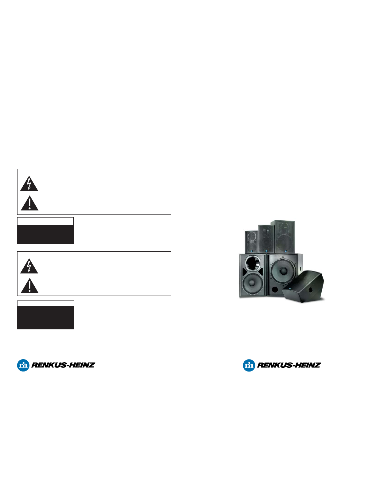
Congratulations on your purchase of a Renkus-Heinz CF Series loudspeaker system. Your CF Series loud-
speaker has been designed to provide you years of trouble-free high performance listening pleasure. We hope
you enjoy it.
IMPORTANT SAFETY INSTRUCTIONS
1. Read these instructions.
2. Keep these instructions.
3. Heed all warnings.
4. Follow all instructions.
5. Do not use this apparatus near water.
6. Clean only with dry cloth.
7. Do not block any ventilation openings. Install in ac-
cordance with the manufacturer’s instructions
8. Do not install near any heat sources such as radia-
tors, heat registers, stoves, or other apparatus (in-
cluding amplifiers) that produce heat.
9. Do not defeat the safety purpose of the polarized or
grounding-type plug. A polarized plug has two blades
with one wider than the other. A grounding type plug
has two blades and a third grounding prong. The
wide blade or the third prong is provided for your
safety. If the provided plug does not fit into your out-
let, consult an electrician for replacement of the obso-
lete outlet.
10. Protect the power cord from being walked on or
pinched particularly at plugs, convenience recepta-
cles, and the point where they exit from the appara-
tus.
11. Make sure the power cord remains readily acces-
sible at all times.
12. Only use attachments/accessories specified by
the manufacturer.
13. Unplug this apparatus during lightning storms or
when unused for long periods of time.
14. Refer all servicing to qualified service personnel.
Servicing is required when the apparatus has been
damaged in any way, such as power-supply cord or
plug is damaged, liquid has been spilled or objects
have fallen into the apparatus, the apparatus has
been exposed to rain or moisture, does not operate
normally, or has been dropped.
“WARNING - TO REDUCE THE RISK OF FIRE OR
ELECTRIC SHOCK, DO NOT EXPOSE THIS APPA-
RATUS TO RAIN OR MOISTURE”
“CAUTION: THESE SERVICING INSTRUCTIONS
ARE FOR USE BY QUALIFIED SERVICE PERSON-
NEL ONLY. TO REDUCE THE RISK OF ELECTRIC
SHOCK DO NOT PERFORM ANY SERVICING
OTHER THAN THAT CONTAINED IN THE OPERAT-
ING INSTRUCTIONS UNLESS YOU ARE QUALI-
FIED TO DO SO”.
IMPORTANT MOUNTING INSTRUCTIONS
To ensure proper air movement for the cooling of the amplifier module, we recommend a minimum of 2 to 3 feet
of clearance in front of the loudspeaker and at least 3 to 4 inches of clearance from the other cabinet surfaces.
Your CF Series loudspeaker was designed to be mounted in an upright position. Please do not place it on its
side on the floor.
Safety certifications do not include methods for mounting loudspeakers.
2 7
Step 1 Step 2
Step 5 Step 6
1. Using the Phillips screwdriver, remove the eight
screws holding the connector plate to the rear of the cabi-
net. Save the screws, you’ll need them to install the am-
plifier.
2. Gently remove the input connector plate from the cabi-
net. You can use a SpeakOn connector as a handle, if
you want
3. Remove the white quick disconnect connector from the
PC board on the inside of the input connector plate by
squeezing the sides of the connector and pulling up. Set
the input connector plate aside and save it in case you
ever need to switch the loudspeaker back to its externally
powered configuration.
4. Prepare PF1-200 amplifiers for installation by setting
the switches on the side of the amplifier according to the
table below. Improper settings on these switches can lead
to loudspeaker damage which is not covered by our war-
ranty.
Prepare PF1-500 amplifiers for installation by setting the
single switch to either “Flat” or “100 Hz Filter”. Use ”Flat”
for full range operation,100 Hz Filter when the amplifier is
being installed in a CFX18S subwoofer. PF1-200R and
PF1-500R RHAON empowered amplifiers do not have
these switches as these settings are controlled remotely.
5. Plug the white quick disconnect connector into the
matching socket on the rear of the power amplifier. The
socket is keyed, so you will have to properly align the
connector with the socket. Make sure that both sides of
the connector latch into place.
6. Insert the power amplifier into the opening in the back
of the loudspeaker and reinstall the eight screws to se-
cure the amplifier into the cabinet. You can use an XLR
connector as a handle.
CF61
CF81
CF121
CF121M
CF151
CF18S
HIGH PASS
FILTER
90
60
30
30
30
30
LOW PASS
FILTER
20K
20K
20K
20K
20K
100
Installing a PF1 series power amplifier into a CFX Series loudspeaker
Adding a power amplifier to a CFX loudspeaker is a quick and easy process. Before you begin, make sure you
have a clean workspace, preferably one with a soft, non-scratching surface and a #2 Phillips Screwdriver.
A step-by-step procedure follows:
Step 3 Step 4

Looping Connector
The male 3-pin XLR type “looping” connector is used to
“loop through” to additional CF Series loudspeakers. It
has “straight through” connections from the Input con-
nector
Status LEDs.
The green “POWER” LED indicates the status of the
amplifier’s power. It turns bright green when the ampli-
fier is turned “on”.
The green “SIGNAL” LED indicates the presence of an
audio signal. It flashes when a signal is present.
The yellow “LIM” LED indicates the amplifier’s protec-
tive limiter is being activated by a high signal level. A
limited amount of flashing during operation is normal; a
continuos glow indicates the amplifier is being over-
driven and the signal level should be reduced.
Attenuation Control
This control adjusts the loudspeaker’s output level.
When it is turned fully clockwise, the amplifier will have
its maximum voltage gain and will deliver its rated out-
put when driven by its rated signal.
As a general rule, setting the control in the full clock-
wise position provides maximum headroom; setting the
control at a lower level maximizes the signal/noise
level.
Power On/Off Switch
This switch is used to turn the amplifier “On” or turn it
“Off”. In the “Off” position, the amplifier is disconnected
from the AC Mains.
“Push To Reset” Circuit Breaker
The “Push To Reset” Circuit Breaker acts as a protec-
tive power line fuse and automatically turns the power
to the amplifier “Off” in case of overload. If the switch
shuts “Off” during normal use, push it back to the “On”
position just one time. Do not attempt to operate the
amplifier by holding the switch in the “on” position. If it
will not stay on by itself, the amplifier needs service.
AC Mains Voltage
The PF1-200 features a universal power supply that
operates from 100 - 240 Volts, 50/60 Hz.
WARNING
1. The AC Mains must be connected to a mains socket outlet with a protective earthing connection.
2. To remove power from the CF Series loudspeaker, disconnect the AC power cord.
Input Connector
The female 3-pin XLR type INPUT connector con-
nects to the amplifiers 10 K Ohms, electronically bal-
anced input. It requires a 1.0 V signal for full rated
output.
Pin 2 is "hot" and pin 3 is "neutral". Pin 1 is chassis
ground. When the amplifier is connected to a bal-
anced source, the shield may either be lifted or con-
nected at the source end. The choice should be
made on the basis of minimum hum.
With an unbalanced source, connect the signal to pin
2 and source ground to pin 3 (connecting the signal to
pin 3 is not recommended. Note: Improper operation
results when only pin 2 or only pin 3 and pin 1
(ground) are used for an unbalanced input.
3
Looping Connector
The male 3-pin XLR type “looping” connector is used
to “loop through” to additional CF Series loudspeakers.
It has “straight through” connections from the Input
connector
Status LEDs.
The green “POWER” LED indicates the status of the
amplifier’s power. It turns bright green when the ampli-
fier is turned “on”.
The green “SIGNAL” LED indicates the presence of an
audio signal. It flashes when a signal is present.
The red “OVERDRIVE” LED flashes red when the am-
plifier is being overdriven
The red “THERMAL” LED glows when the amplifier’s
over-temperature sensor has shut the amplifier down.
Volume “Up” and “Down” Push Buttons
Adjust the loudspeaker’s output level up and down.
Power On/Off Switch
This switch is used to turn the amplifier “On” or turn it
“Off”. In the “Off” position, the amplifier is disconnected
from the AC Mains.
Voltage Selector Switch
This switch selects between 110/120 V and 220/240 V
50/60 Hz operation.
AC Mains Fuse
Protective power line fuse; replace only with correct
size and type.
If the fuse blows a second time, the amplifier needs
service.
WARNING
1. The AC Mains must be connected to a mains socket outlet with a protective earthing connection.
2. The PF1-500R operates from either 110/120 V, 50/60 Hz or 220/240V 50/60 Hz. Check the Voltage Se-
lector setting before connecting power to the amplifier.
3. To remove power from the CF Series loudspeaker, disconnect the AC power cord.
Input Connector
The female 3-pin XLR type INPUT connector con-
nects to the amplifiers 10 K Ohms, electronically bal-
anced input. It requires a 1.0 V signal for full rated
output.
Pin 2 is "hot" and pin 3 is "neutral". Pin 1 is chassis
ground. When the amplifier is connected to a bal-
anced source, the shield may either be lifted or con-
nected at the source end. The choice should be
made on the basis of minimum hum.
With an unbalanced source, connect the signal to pin
2 and source ground to pin 3 (connecting the signal to
pin 3 is not recommended. Note: Improper operation
results when only pin 2 or only pin 3 and pin 1
(ground) are used for an unbalanced input.
6
PF1-500R Amplifier Module
The PF1-500R RHAON empowered power amplifier. was developed by Renkus-Heinz engineers to match the loud-
speaker’s high performance transducers. It includes comprehensive signal processing and protective circuitry along with
RHAON, which adds digital audio distribution and remotely located control and supervision to the loudspeaker. For addi-
tional information on RHAON, please refer to the RHAON Users Manual, Renkus-Heinz document # RH 611.
PF1-200 Amplifier Module
Your PF1-200 power amplifier was developed by Renkus-Heinz engineers to match the loudspeaker’s high per-
formance transducers and includes comprehensive signal processing and protective circuitry.

Looping Connector
The male 3-pin XLR type “looping” connector is used
to “loop through” to additional CF Series loudspeakers.
It has “straight through” connections from the Input
connector.
Status LEDs.
The green “POWER” LED indicates the status of the
amplifier’s power. It turns bright green when the ampli-
fier is turned “on”.
The green “SIGNAL” LED indicates the presence of an
audio signal. It flashes when a signal is present.
The yellow “LIM” LED indicates the amplifier’s protec-
tive limiter is being activated by a high signal level. A
limited amount of flashing during operation is normal;
a continuos glow indicates the amplifier is being over-
driven and the signal level should be reduced.
Attenuation Control
This control adjusts the loudspeaker’s output level.
When it is turned fully clockwise, the amplifier will have
its maximum voltage gain and will deliver its rated out-
put when driven by its rated signal.
As a general rule, setting the control in the full clock-
wise position provides maximum headroom; setting
the control at a lower level maximizes the signal/noise
level.
Power On/Off Switch
This switch is used to turn the amplifier “On” or turn it
“Off”. In the “Off” position, the amplifier is disconnected
from the AC Mains.
Voltage Selector Switch
This switch selects between 110/120 V and 220/240 V
50/60 Hz operation.
AC Mains Fuse
Protective power line fuse; replace only with correct
size and type. If the fuse blows a second time, the am-
plifier needs service.
WARNING
1. The AC Mains must be connected to a mains socket outlet with a protective earthing connection.
2. The PF1-500 operates from either 110/120 V, 50/60 Hz or 220/240V 50/60 Hz. Check the Voltage Selec-
tor setting before connecting power to the amplifier.
3. To remove power from the CF Series loudspeaker, disconnect the AC power cord.
Input Connector
The female 3-pin XLR type INPUT connector con-
nects to the amplifiers 10 K Ohms, electronically bal-
anced input. It requires a 1.0 V signal for full rated
output.
Pin 2 is "hot" and pin 3 is "neutral". Pin 1 is chassis
ground. When the amplifier is connected to a bal-
anced source, the shield may either be lifted or con-
nected at the source end. The choice should be
made on the basis of minimum hum.
With an unbalanced source, connect the signal to pin
2 and source ground to pin 3 (connecting the signal to
pin 3 is not recommended. Note: Improper operation
results when only pin 2 or only pin 3 and pin 1
(ground) are used for an unbalanced input.
5
Looping Connector
The male 3-pin XLR type “looping” connector is used
to “loop through” to additional CF Series loudspeakers.
It has “straight through” connections from the Input
connector
Status LEDs.
The green “POWER” LED indicates the status of the
amplifier’s power. It turns bright green when the ampli-
fier is turned “on”.
The green “SIGNAL” LED indicates the presence of an
audio signal. It flashes when a signal is present.
The red “OVERDRIVE” LED flashes red when the am-
plifier is being overdriven
The red “THERMAL” LED glows when the amplifier’s
over-temperature sensor has shut the amplifier down.
Volume “Up” and “Down” Push Buttons
Adjust the loudspeaker’s output level up and down.
Power On/Off Switch
This switch is used to turn the amplifier “On” or turn it
“Off”. In the “Off” position, the amplifier is disconnected
from the AC Mains.
“Push To Reset” Circuit Breaker
The “Push To Reset” Circuit Breaker acts as a protec-
tive power line fuse and automatically turns the power
to the amplifier “Off” in case of overload.
If the switch shuts “Off” during normal use, push it
back to the “On” position just one time. Do not attempt
to operate the amplifier by holding the switch in the
“on” position. If it will not stay on by itself, the amplifier
needs service.
WARNING
1. The AC Mains must be connected to a mains socket outlet with a protective earthing connection.
2. To remove power from the CF Series loudspeaker, disconnect the AC power cord.
Input Connector
The female 3-pin XLR type INPUT connector con-
nects to the amplifiers 10 K Ohms, electronically bal-
anced input. It requires a 1.0 V signal for full rated
output.
Pin 2 is "hot" and pin 3 is "neutral". Pin 1 is chassis
ground. When the amplifier is connected to a bal-
anced source, the shield may either be lifted or con-
nected at the source end. The choice should be
made on the basis of minimum hum.
With an unbalanced source, connect the signal to pin
2 and source ground to pin 3 (connecting the signal to
pin 3 is not recommended. Note: Improper operation
results when only pin 2 or only pin 3 and pin 1
(ground) are used for an unbalanced input.
4
PF1-200R Amplifier Module
The PF1-200R RHAON empowered power amplifier. was developed by Renkus-Heinz engineers to match the
loudspeaker’s high performance transducers. It includes comprehensive signal processing and protective cir-
cuitry along with RHAON, which adds digital audio distribution and remotely located control and supervision to
the loudspeaker. For additional information on RHAON, please refer to the RHAON Users Manual, Renkus-
Heinz document # RH 611.
PF1-500 Amplifier Module
The PF1-500 power amplifier was developed by Renkus-Heinz engineers to match the loudspeaker’s high per-
formance transducers and includes comprehensive signal processing and protective circuitry.
This manual suits for next models
9
Table of contents
Other Renkus-Heinz Speakers manuals

Renkus-Heinz
Renkus-Heinz VARIA VA101-7 User manual

Renkus-Heinz
Renkus-Heinz Loudspeakers User manual

Renkus-Heinz
Renkus-Heinz PN Series User manual

Renkus-Heinz
Renkus-Heinz PF1-500 User manual

Renkus-Heinz
Renkus-Heinz STLA9 User manual

Renkus-Heinz
Renkus-Heinz Iconyx IC Live ILC-F-DUAL User manual

Renkus-Heinz
Renkus-Heinz Iconyx ICX7-II User manual

Renkus-Heinz
Renkus-Heinz Sygma SG61 User manual

Renkus-Heinz
Renkus-Heinz iConyx IC8 User manual

Renkus-Heinz
Renkus-Heinz Loudspeaker User manual