manuals.online logo
Brands
  1. Home
  2. •
  3. Brands
  4. •
  5. Request
  6. •
  7. Cables And Connectors
  8. •
  9. Request iQ.SCK2 Instruction manual

Request iQ.SCK2 Instruction manual

Connection Instructions for the
iQ.SCK2 and iQ.SCK4
© 2008 ReQuest Inc.
100 Saratoga Village Blvd
Suite 44
Ballston Spa, NY 12020
www.request.com/support
1-800-236-2812
Parts List
Connection Guide
1 - USB to 2 or 4-Port Serial (RS 232) Adapter
1 - 6’ F/F (RS 232) Cable (Black)
1 - 6’ F/M (RS 232) Cable (Gray)
Additional Parts Required (Not Included)
Rack mount equipment
USB hub (required if a TS15/12 is installed)
Take note of the inputs used
for each device. It is important for
later configuraton instructions.
After connections are made,
power devices on in this order:
1. Tuners (if connected)
2. iQ.IMA6
3. iQ.IMS
Ensure that ALL devices are
completely powered down before
connecting.
If you do not have an open
USB port on the iQ.IMS, a USB
hub will be required.
Note: The Polk XM Tuner is shown as an example. If the device you are connecting has multiple
tuners, you must connect each of them to an input on the iQ.IMA6.
Serial Cable Kits
RCA Line Level
RCA Line Level
RCA Line Level
iQ Configuration for Polk XRt12
Click on the "iQ Configuration" link at
the bottom of the screen.
Select "Serial" from the control types popup.
Click on the link for " Devices" Click on the "Add Device" link located
above the Devices list
Click on “Detect”
This means the Polk XRt12 is successfully detected. Drag your tuner to the correct serial port on the right.
Step 8
Select “Tuner” then “Polk XRt12 Tuner” from the “Add Serial Device” box
On a networked computer, open a web browser and go to the IP address displayed on the front
of the iQ.IMS then follow these instructions:
In the event that you cannot
detect the Polk XRt12, check the
cable connections, ensure the XRt12's
power is on, and verify that you have
selected the correct the port A or B in
the Device Location field. Note: You
may safely attempt to detect the
XRt12 on either Port 1 or Port 2 if you
are unsure which port has been
connected.
The Polk tuner is
being shown here as an
example. Setup for other
supported tuners would
be similar.
If the device you
are connecting has
multiple tuners, you will
have to do this for each.
Step 1 Step 2 Step 3
Step 4 Step 5
Step 6
Step 7
You will see the Polk XRt12 device in
the list of available sources (left).
Step 10
Place the Polk XRt12 source from the left
to the input slot on the right where you
have connected the tuner to the IMA
(refer to Connection Guide).
Step 11
You may rename
the source from the
default "Polk XRt12
XM Tuner" to a name
you wish to appear on
the iQ interfaces by
clicking the “Edit” link
Optional: You may
rearrange the order in
which the iQ's configured
sources appear on the iQ
interfaces (TS35 and TS15).
Click on the link "3: Source
Order" on the top of the
screen and drag the
available sources to the
various slots. For more
information consult the
ReQuest iQ.IMS Installer
Guide.
click and drag
Click on the “Sources”
link to return to the
Sources configuration
Step 9
click and drag
Select ““DDeevviicceeCCoonnttrrooll””
from the AArreeaamenu at
the top.
Step 8
Setup Guide for the iQ.SCK2 and iQ.SCK4 Page 2
iQ Configuration for Multiple iQ.IMA6 Amplifiers
This means the IMA6 is successfully detected.
On a networked computer, open a web browser
and go to the IP address displayed on the front of the iQ.IMS then follow these instructions:
When wiring a
multiple-IMA6 system, you
must connect the Source
Loop Outputs of the first
IMA6 to the Source Inputs
of the next IMA6.
ReQuest currently
supports up to 7 IMA6s
per system connected in
this fashion.
Step 7
You will see that the speakers connected to the new IMA6 will be
numbered 22..11,,22..22,,eettcc....(or 3.x, or 4.x depending on the number
of IMAs connected). Simple drag these new speakers to the
appropriate rooms and you are done.
Step 10
click and drag
When you have successfully
detected the IMA6, select
““RRoooommss””from the AArreeaamenu
at the top of the screen.
Step 8
Click on the "iQ Configuration" link at
the bottom of the screen. Click on the link for " Devices" Click on the "Add Device" link located
above the Devices list
Step 1 Step 2 Step 3
Select "Serial" from the control types popup. Select “Switch” then “ReQuest IMA6” from the “Add Serial Device” list
Step 4 Step 5
Setup Guide for the iQ.SCK2 and iQ.SCK4 Page 3
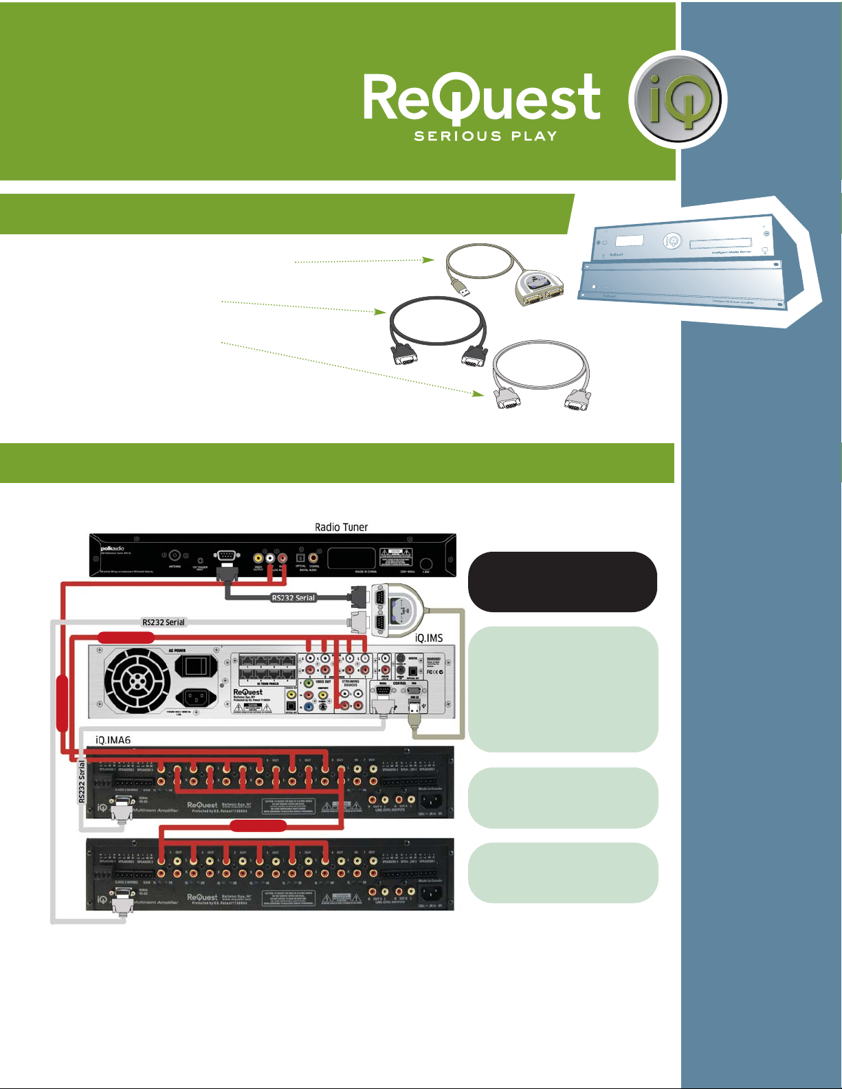
Wiring suggestion for the iQ.SCK4 with 3 IMA6s (18 Audio Zones)
The lightning flash with arrowhead symbol, within an equilateral
triangle, is intended to alert the user to the presence of uninsulated
dangerous voltage within the product’s enclosure that may be of
sufficient magnitude to constitute a risk of electric shock to persons.
Warning: To reduce the risk of fire or electric shock, do not expose this
apparatus to rain or moisture
The exclamation point within an equilateral triangle is intended to alert
the user to the presence of important operating and maintenance
(servicing) instructions in the literature accompanying the appliance.
CAUTION
TO REDUCE RISK OF ELECTRICAL SHOCK, DO NOT
REMOVE COVER. NO USER-SERVICEABLE PARTS INSIDE.
REFER SERVICING TO QUALIFIED SERVICE PERSONNEL.
Read, keep and follow these instructions.
Do not use this device near water.
Device shall not be exposed to dripping or splashing, and no objects
filled with liquids shall be placed on the apparatus.
Clean only with a dry cloth.
Do not block any ventilation openings. Install according to the
manufacturer’s instructions.
Do not install near any heat sources such as radiators, heat registers,
stoves, or other device (including amplifiers) that produce heat.
Do not defeat the safety purpose of the polarized or ground plug. If the
provided plug does not fit into your outlet, consult an electrician
regarding installation of a modern polarized outlet.
Protect the power cord from being walked on or pinched.
Only use attachments/accessories specified by the manufacturer.
Protect this device through the use of proper UPS or surge protection
equipment.
Refer all servicing to qualified service personnel.
IMPORTANT SAFETY WARNINGS
1.
2.
3.
4.
5.
6.
7.
8.
9.
10.
11.
Setup Guide for the iQ.SCK2 and iQ.SCK4 Page 4
Setup is similar to other
configuration shown. Be sure to connect
the Source Outputs of each IMA6 to the
Source Inputs of the next IMA6 in line.
The remaining Serial connection on your
SCK4 can go to another tuner, another
supported serial control device, or a
fourth IMA6.
To additional tuner, 4th IMA6,
or other supported serial
device.
RCA Line Level
RCA Line Level
RCA Line Level
RCA Line Level

This manual suits for next models

1

Popular Cables And Connectors manuals by other brands

Philips SWA7533W/10 Information

Philips

Philips SWA7533W/10 Information

Philips SWA3162W Specifications

Philips

Philips SWA3162W Specifications

Philips SWV3515S/10 user manual

Philips

Philips SWV3515S/10 user manual

PowerBridge NuIPC cPCIS-6230R Series user guide

PowerBridge

PowerBridge NuIPC cPCIS-6230R Series user guide

Westone Bluetooth Cable user manual

Westone

Westone Bluetooth Cable user manual

Eaton EU4A-RJ45-CAB2 Instruction leaflet

Eaton

Eaton EU4A-RJ45-CAB2 Instruction leaflet

HRS BM25 Series manual

HRS

HRS BM25 Series manual

solarwatt AZ-TM-PME-1125 installation guide

solarwatt

solarwatt AZ-TM-PME-1125 installation guide

Eaton DT400 installation instructions

Eaton

Eaton DT400 installation instructions

DreamGEAR BoomChat user guide

DreamGEAR

DreamGEAR BoomChat user guide

Unex 93 ALU. Instructions and safety documentation

Unex

Unex 93 ALU. Instructions and safety documentation

Leviton 21415-LB Installation

Leviton

Leviton 21415-LB Installation

Monster ICRUZE INTERFACE CABLE MPC FX IM-MB1 Installation & user guide

Monster

Monster ICRUZE INTERFACE CABLE MPC FX IM-MB1 Installation & user guide

Techly ICKV108DTY user manual

Techly

Techly ICKV108DTY user manual

KStrong FC409151 User instruction manual

KStrong

KStrong FC409151 User instruction manual

Xantech MRCKPSP installation instructions

Xantech

Xantech MRCKPSP installation instructions

Weidmüller BLF 7.62HP Series Assembly instructions

Weidmüller

Weidmüller BLF 7.62HP Series Assembly instructions

LEGRAND ON-Q HT2302B quick start guide

LEGRAND

LEGRAND ON-Q HT2302B quick start guide

manuals.online logo
manuals.online logoBrands
  • About & Mission
  • Contact us
  • Privacy Policy
  • Terms and Conditions

Copyright 2025 Manuals.Online. All Rights Reserved.