Research C104 User manual

February 26, 2015
Research, Inc. • USA • Ph: 952.949-9009 • Fax: 952.949-9559 • tsdsales@researchinc.com • www.researchinc.com
Instruction Manual
Cool
IR
Model C104 - Cooling System

2Research, Inc. • USA • Ph: 952.9419-9009 • Fax: 952.949-9559 • tsdsales@researchinc.com • www.researchinc.com
Table of Contents
List of Figures....................................................................................................................... 2
Section 1 - Introduction ........................................................................................................ 3
Section 2 - Installation and Operation:.................................................................................. 4
Safety............................................................................................................................... 4
Sizing the C104 to the heater……………………………………………………………………5
Installation........................................................................................................................ 5
Operation.......................................................................................................................... 7
Section 3 - Specifications..................................................................................................... 7
Section 4 - Maintenance and Parts....................................................................................... 8
Maintenance..................................................................................................................... 8
Exploded view ……………………………………………………………………………………..9
Part list…………………………………………………………………………………………….10
List of Figures / Tables
Figure 1 - C104 connection side ......................................................................................... 3
Figure 2 - exploded view ……………………………………………………………………………9
Table 1 - Heater / cooler sizing …………………………………………………………………….5
Table 2 - cooling performance………………………………………………………………………6
Table 3 - spare parts ………..……………………………………………………………………….8
Revision History
Revision
Description
ECN Number
By
Date
A
Initial Release
KJN
11/01/2013
B
Add 230v
KJN
10/21/2014
C
Cooling spec
KJN
02/26/2015

Research, Inc. • USA • Ph: 952.949-9009 • Fax: 952.949-9559• tsdsales@researchinc.com • www.researchinc.com 3
Section 1 - Introduction
The Model C104 is a self-contained heat exchanger designed to provide circulating coolant
for small Research Inc. aluminum-reflector heaters. Figure 1 below shows the C104
connection side. Power to the motor is provided with a 10ft power cord and molded plug.
The unit includes an industrial grade brass pump, copper coil, 120/230volt motor with fan
and 4 gallon (15 liter) reservoir. Two ¼” NPT fittings for coolant inlet/outlet are located on
the side plate.
Figure 1 - C104 connections
Coolant
outlet
Coolant
inlet

4Research, Inc. • USA • Ph: 952.9419-9009 • Fax: 952.949-9559 • tsdsales@researchinc.com • www.researchinc.com
Section 2 - Installation and Operation:
Safety
The maximum water/glycol temperature is 140ºF (60ºC). Precaution should be taken to
ensure this temperature is not exceeded. Refer to the installation section for proper sizing
instructions.
WARNING!
Hazardous voltages are present within the heating/cooling/control system. Setting the set
point potentiometer or control signal to minimum does NOT eliminate these hazardous
voltages.
Always remove AC line voltage from the system before making contact with internal
assemblies, line or load wiring, or fuses.
CAUTION!
Up to 480 volts AC may be present at IR heater with longer lengths (25” and 38”).
Do not make any wiring connections when power is applied.
Disconnect power before performing any maintenance or service to the system.
Use extreme caution when adjusting calibration potentiometers on modules when
power is applied.
Always use an isolated oscilloscope for checking waveforms.
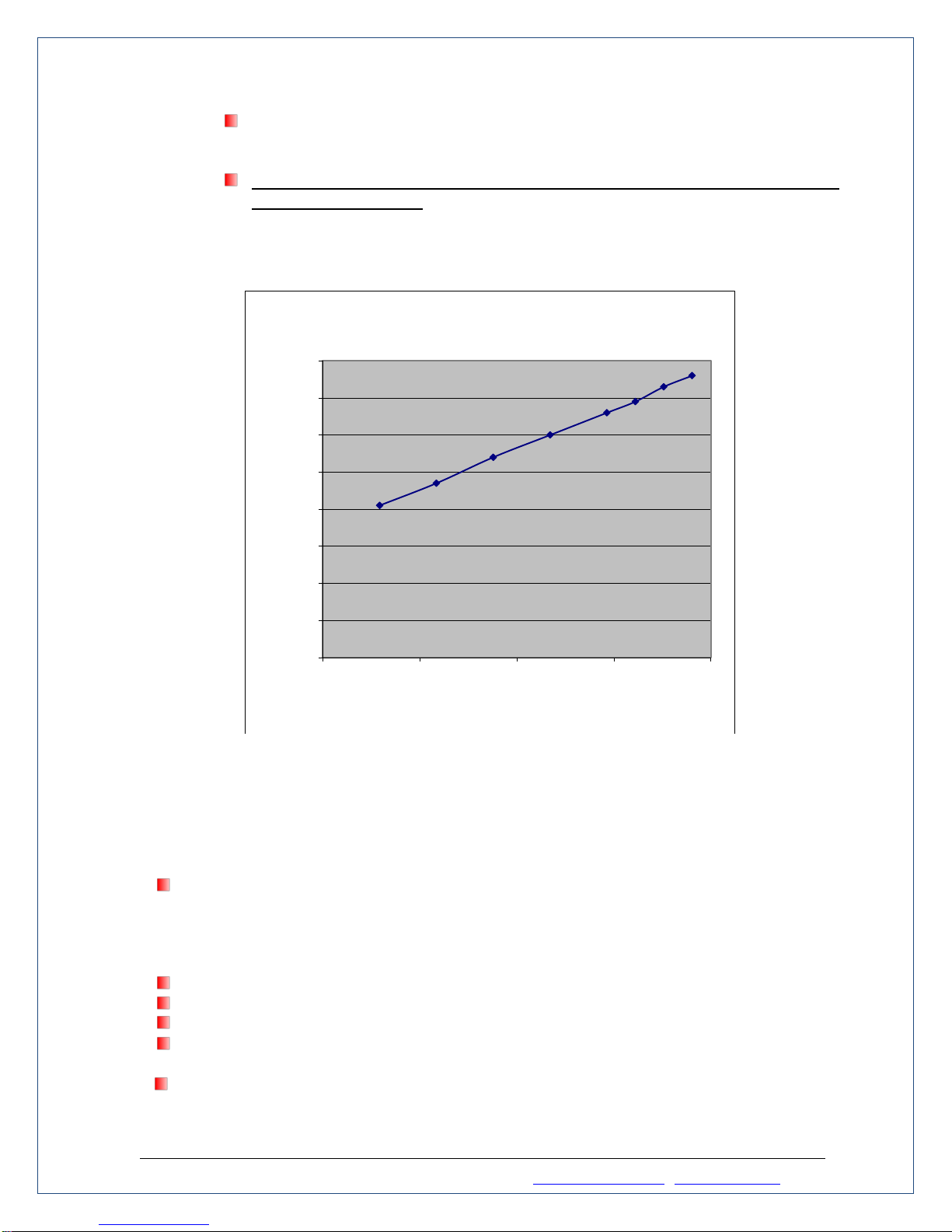
Sizing
The C104 can handle up to 5 KW of cooling load. The amount of cooling load is dependent
upon the heater style, lamp wattage, and heating application. Table 1 shows how to size
the C104. These steps are outlined below:
1. Determine heater wattage –This is a simple calculation based upon the wattage of
the lamps in the heater times the number of lamps in the system.
2. Determine the cooling factor (Fc). This takes into account how much heat is going
into the reflector that will be carried away by the cooling system.
3. Determine the number of C104 units required. Each C104 can handle up to 5 KW. If
the calculated cooling load is less than 5 KW, then one unit will work. Multiple C104
units can be used in parallel. Consult factory.

Research, Inc. • USA • Ph: 952.949-9009 • Fax: 952.949-9559• tsdsales@researchinc.com • www.researchinc.com 5
Size C104 Cool IR
1. Determine heater(s) wattage
Example: E4-05 w/500 watt lamps
Wattage = 4 x 500 = 2000 watts
2. Determine cooling factor (Fc)
Model
Fc
Description
E4
0.9
All
5194
0.9
Multiple 5194's facing each other
5194
0.7
5194(s) facing target > 800 ºC
5194
0.5
5194(s) facing target from 400 ºC to 800 ºC
5194
0.3
5194(s) facing target < 400 ºC
5306B
0.9
Multiple 5306B's facing each other
5306B
0.6
5306B(s) facing target > 800 ºC
5306B
0.4
5306B(s) facing target from 400 ºC to 800 ºC
5306B
0.2
5306B(s) facing target < 400 ºC
3. Calculate cooling load (Lc)
Lc = Heater wattage x Fc
Example: Lc = 2000 x 0.9 = 1800 watts
4. Determine number of C104's needed
C104 rating = 5000 watts
Lc = 1800 watts
1 - Model C104 required
Table 1 - C104 Heater/Cooler Sizing
Installation:
1. Cut two lengths of poly tubing supplied with the IR heater to connect to the cooling
unit to the heater. Both IR heater and cooling unit are supplied with push-to-connect
fittings for simple installation without tools. Cut tubing square for positive leak free
connections.
2. Flow direction through the heater does not matter. If using the heater protection kit
(HPK, p/n 107109-001) then follow the flow directions provided on the enclosure
3. Remove filler cap and fill reservoir with one of the following coolant types:
Add mixture of distilled water (3 gallons) and propylene glycol (1 gallon, RV
type, pink color) solution. Checked monthly and changed as needed.

6Research, Inc. • USA • Ph: 952.9419-9009 • Fax: 952.949-9559 • tsdsales@researchinc.com • www.researchinc.com
Add mixture of distilled water (3 gallons) ethylene glycol (1 gallon, automotive
type compatible with aluminum) solution. Check every 6 months and change
as needed.
Do not use anti-freeze with stop leak additive, which will clog the filter screen
and damage the pump.
4.) Connect power to 115/230vac source
Table 2 - C104 Cooling Performance
Caution:
Coolant should be allowed to flow through the system continuously, if not the pump will
run hot, shortening its life if allowed to operate for more than a short period against a
closed or plugged discharge. When used with automatic equipment having a coolant
solenoid valve, bypass the solenoid or, wire the cooler into the equipment so that it
operates only during operation.
Do not transport or attempt repair unless unit is disconnected from power source.
Operation of the pump without coolant will cause serious damage.
Pump warranty is void if user opens or disassembles the pump.
Pump life and fitting life will be reduced if coolant temperature in tank exceeds 140F
(60C). Table 2 shows the coolant temperature as a function of cooling KW.
Operate the cooler only at the voltage and frequency stamped on the serial nameplate
(120V, 230V, 50/60 Hz),
0
20
40
60
80
100
120
140
160
0.0 1.0 2.0 3.0 4.0
Water Temp (F)
Cooling KW
CoolIR Performance

Research, Inc. • USA • Ph: 952.949-9009 • Fax: 952.949-9559• tsdsales@researchinc.com • www.researchinc.com 7
Operation
The C104 system needs to run when the heater is being run. After the heater is shut off, the
user should continue to run the C104 system for 3 –5 minutes to allowing the heater to cool.
Section 3 - Specifications
Motor voltage
Max
current
draw
IEC
Cooling
Capacity
Tank
Capacity
Dimensions
Weight
115vac,
50/60Hz
5.9A
(50Hz)
4.7A
(60Hz)
1780W
(6070
BTU/hr.)
1.1qt./min
(1 L/min)
4 gal
(15 L)
H: 16.25 in.
(413mm)
W: 15.25 in.
(387mm)
D: 18.75 in.
(476mm)
40lb
(18kg)
Motor voltage
Max
current
draw
IEC
Cooling
Capacity
Tank
Capacity
Dimensions
Weight
230vac,
50/60Hz
3.5A
(50Hz)
2.5A
(60Hz)
1780W
(6070
BTU/hr.)
1.1qt./min
(1 L/min)
4 gal
(15 L)
H: 16.25 in.
(413mm)
W: 15.25 in.
(387mm)
D: 18.75 in.
(476mm)
40lb
(18kg)
Pump Capacity:
100 psi max. 1.5 gpm (5.68 lpm) @ 50 psi.
Heat Exchanger:
High efficiency, copper core, rustproof
Motor Voltage / Amps:
115 Volt AC, single phase, 50/60 Hz, 4.7A 60Hz, 5.9A 50Hz
230 Volt AC, single phase, 50/60 Hz, 2.5A 60Hz, 3.5A 50Hz
Coolant Connections:
1/4" N.P.T. supplied with push-to-connect fitting for ¼” tubing
Net Weight:
40 lbs. (25.4 kg)
Dimensions:
16.25 inches (413 mm) H, 15.25 inches (387 mm) W, 18.75 inches (476 mm) D

8Research, Inc. • USA • Ph: 952.9419-9009 • Fax: 952.949-9559 • tsdsales@researchinc.com • www.researchinc.com
Section 4 - Maintenance and Parts
Routine Maintenance
Perform the following maintenance on a minimum of 3 month time cycle:
Remove dust from radiator by means of compressed air, in order to insure optimum
cooler performance.
Check the filter screen, by removing the 15/16" acorn nut on the pump. Clean the filter
or replace as necessary.
Add mixture of distilled water (3 gallons) and propylene glycol (1 gallon, RV type, pink
color) solution. Checked monthly and changed as needed.
Add mixture of distilled water (3 gallons) ethylene glycol (1 gallon, automotive type
compatible with aluminum) solution. Check every 6 months and change as needed.
Do not use anti-freeze with stop leak additive, which will clog the filter screen and
damage the pump.
Options:
Model #
Description
Part Number
C100 - E4- kit
E4 fitting kit
C100 - FHK
Fitting and hose kit
C100 “T” kit
“tee” kit to connect two heaters
PK
Heater protection Kit
107109-001
Manifold-4
4 port, aluminum
120068-001
Maniford-6
6 port, aluminum
120068-002
Table 3 - C104 Parts and Kits
C104 Ordering Information
Model #
Description
C104-120
5kW heat exchanger, 120v motor
C104-120-PK
5kW heat exchanger, 120v motor , heater protection kit
C104-230
5kW heat exchanger, 230v motor
C104-230-PK
5kW heat exchanger, 230v motor, heater protection Kit

Research, Inc. • USA • Ph: 952.949-9009 • Fax: 952.949-9559• tsdsales@researchinc.com • www.researchinc.com 9
Figure 2 - Exploded view

10 Research, Inc. • USA • Ph: 952.9419-9009 • Fax: 952.949-9559 • tsdsales@researchinc.com • www.researchinc.com
C104 Parts List
Figure 2 - above
Item
No.
Description
Quantity
Used
1
Wire form, radiator end
1
2
Radiator, coolant tank w/ weather stripping
1
3
Hose, rubber braided, .375 ID x .650 OD x 12”
2
4
Hose, rubber braided, .375 ID x .650 OD x 10.5
2
6
Label, caution incorrect coolant
1
7
Label, warning general pre caution (CE Model)
1
8
Cap, tank screw-on w/ screw type vent
1
9
Tank., coolant
1
10
Bushing
2
11
Barbed hose fittings
2
12
Insulator, front panel
1
13
Nut, hex, jam .500-20
2
14
Washer, toothed .512ID x .900 OD
2
15
Plate, Identification
1
17
Fitting, hose barbed
2
18
Motor, 115vac / 230v 50/60Hz 1425/1750RPM
1
19
Pump,
1
20
Fitting, barbed, 3/8” NPT
2
21
Coupler, drive pump
1
Strainer –screen, not shown
1
22
Cable, pwr, 115vac 16ga. , 3conductor, 10ft
1
24
Bracket, motor mount
1
25
Label, warning moving parts
1
26
Blade, fan 10”
1
27
Tubing,
1
Table of contents
Popular Accessories manuals by other brands

Jung
Jung 65 WIS manual

Yiroka
Yiroka WF006-718D user manual

Stramatel
Stramatel Multisport Compact Series TECHNICAL DATA - INSTALLATION INSTRUCTIONS

IstaGoal
IstaGoal SELF WEIGHTED ROLLER GOAL quick start guide

Griesser
Griesser Soloscreen Operating and maintenance instructions

PCB Piezotronics
PCB Piezotronics 137A Installation and operating manual