Sentera Controls FCMFFB-R Service manual

FCMFXB-R INTELLIGENT CO2
SENSOR WITH BUZZER
Mounting and operating instructions

www.sentera.eu
MIW-FCMFXB-R-EN-000-19/02/2021 2 - 10
back to the table of contents
FCMFXB-R INTELLIGENT CO2SENSOR WITH
BUZZER
Table of contents
SAFETY AND PRECAUTIONS 3
PRODUCT DESCRIPTION 4
ARTICLE CODE 4
INTENDED AREA OF USE 4
TECHNICAL DATA 4
STANDARDS 4
OPERATIONAL DIAGRAMS 5
WIRING AND CONNECTIONS 6
MOUNTING INSTRUCTIONS IN STEPS 6
OPERATING INSTRUCTIONS 8
VERIFICATION OF INSTALLATION 9
TRANSPORT AND STORAGE 9
WARRANTY AND RESTRICTIONS 9
MAINTENANCE 9

www.sentera.eu
MIW-FCMFXB-R-EN-000-19/02/2021 3 - 10
back to the table of contents
FCMFXB-R INTELLIGENT CO2SENSOR WITH
BUZZER
SAFETY AND PRECAUTIONS
Read all the information, the datasheet, Modbus map, mounting and operating
instructions and study the wiring and connection diagram before working with the
product. For personal and equipment safety, and for optimum product performance,
make sure you entirely understand the contents before installing, using, or maintaining
this product.
For safety and licensing (CE) reasons, unauthorised conversion and/ or modifications
of the product are inadmissible.
e product should not be exposed to abnormal conditions, such as extreme
temperatures, direct sunlight or vibrations. Long-term exposure to chemical
vapours in high concentration can affect the product performance. Make sure the
work environment is as dry as possible; avoid condensation.
All installations shall comply with local health and safety regulations and local
electrical standards and approved codes. is product can only be installed by
an engineer or a technician who has expert knowledge of the product and safety
precautions.
Avoid contacts with energised electrical parts. Always disconnect the power
supply before connecting, servicing or repairing the product.
Always verify that you apply appropriate power supply to the product and use
appropriate wire size and characteristics. Make sure that all the screws and nuts
are well tightened and fuses (if any) are fitted well.
Recycling of equipment and packaging should be taken into consideration and these
should be disposed of in accordance with local and national legislation/regulations.
In case there are any questions that are not answered, please contact your
technical support or consult a professional.

www.sentera.eu
MIW-FCMFXB-R-EN-000-19/02/2021 4 - 10
back to the table of contents
FCMFXB-R INTELLIGENT CO2SENSOR WITH
BUZZER
PRODUCT DESCRIPTION
e FCMFXB-R series are intelligent sensors with integrated audible alarm. ey
measure temperature, relative humidity and carbon dioxide levels. Based on the
temperature and relative humidity measurements, the dew point is calculated. eir
algorithm controls a single analogue / modulating output based on the measured
T, rH and CO2values, which can be used to directly control an EC fan or an actuator
powered damper. All parameters are accessible via Modbus RTU.
ARTICLE CODE
Article code Power supply Imax
FCMFFB-R 18—34 VDC 109 mA
FCMFGB-R 18—34 VDC / 15—24 VAC ± 10 % 190 mA
INTENDED AREA OF USE
■Demand controlled ventilation based on temperature, relative humidity and CO2
levels
■Suitable for residential and commercial buildings
■For indoor use only
TECHNICAL DATA
■Inset or surface mounting
■Bootloader for updating the firmware via Modbus RTU communication
■Analogue / modulating output type:
►0—10 VDC mode: min. load 50 kΩ (RL≥ 50 kΩ)
►0—20 mA: max. load 500 Ω (RL≥ 500 Ω)
►PWM (open-collector type): PWM Frequency: 1 kHz, RL≥ 50 kΩ; PWM voltage
level 3,3 or 12 VDC
■Selectable temperature range: -30—70 °C
■Selectable relative humidity range: 0—100 %
■Selectable CO2range: 0—2.000 ppm
■Replaceable CO2sensor element
■Replaceable audible alarm module, settable via Modbus register (OFF, continuous
or pulsed)
■3 LEDs with adjustable light intensity for status indication
■Accuracy: ±0,4 °C (range: 0—50 °C); ±3 % rH (range: 0—100 % rH); ±30 ppm CO2
(range: 400—2.000 ppm)
■Enclosure:
►internal: plastic RABS, black
►external: ABS, white
►cover: ASA, white
■Protection standard: IP30 (according to EN 60529)
■Typical range of use:
►temperature: 0—50 °C
►rel. humidity: 0—95 % rH (non-condensing)
►CO2: 400—2.000 ppm
■Storage temperature: -10—60 °C

www.sentera.eu
MIW-FCMFXB-R-EN-000-19/02/2021 5 - 10
back to the table of contents
FCMFXB-R INTELLIGENT CO2SENSOR WITH
BUZZER
STANDARDS
■Low Voltage Directive 2014/35/EC
►EN 60529:1991 Degrees of protection provided by enclosures (IP Code)
Amendment AC:1993 to EN 60529
►EN 60730-1:2011 Automatic electrical controls for household and similar use -
Part 1: General requirements
■EMC Directive 2014/30/EC
►EN 60730-1:2011 Automatic electrical controls for household and similar use -
Part 1: General requirements
►EN 61000-6-1:2007 Electromagnetic compatibility (EMC) - Part 6-1: Generic
standards-Immunity forresidential, commercialandlightindustrialenvironments
EN 61000-6-3:2007 Electromagnetic compatibility (EMC) - Part 6-3: Generic
standards - Emission standard for residential, commercial and light-industrial
environments Amendments A1:2011 and AC:2012 to EN 61000-6-3
►EN 61326-1:2013 Electrical equipment for measurement, control and laboratory
use - EMC requirements - Part 1: General requirements
►EN 61326-2-3:2013 Electrical equipment for measurement, control and
laboratory use - EMC requirements - Part 2-3: Particular requirements - Test
configuration, operational conditions and performance criteria
■WEEE 2012/19/ EC
■RoHs Directive 2011/65/EC
OPERATIONAL DIAGRAMS
AO1, max
range
AO1, min
range
60
40
100
0
rH Min range
-30
0
0CO2Min range CO2Max range
Max
Min
T Min range T Max range
rH Max range
AO1 [%]
70
100
2.000
rH [%]T [°C] CO2[ppm]
CAUTION e output changes automatically depending on the highest temperature, relative
humidity or CO2values, i.e. the highest of the three output values controls the
output. See the green line in the operational diagram above.

www.sentera.eu
MIW-FCMFXB-R-EN-000-19/02/2021 6 - 10
back to the table of contents
FCMFXB-R INTELLIGENT CO2SENSOR WITH
BUZZER
10
20
30
40
50
60
70
80
90
100
Minimum
range
Minimum
alert
Maximum
alert
Output [%]
T [°C] / rH [%] / CO2 [ppm]*
Maximum
range
*LED indications - T, rH or CO2 (default)
WIRING AND CONNECTIONS
Article type FCMFFB-R FCMFGB-R
V+ 18—34 VDC 18—34 VDC 15—24 VAC ±10%
V- Ground Common
ground AC ~
AModbus RTU (RS485), signal A
/B Modbus RTU (RS485), signal /B
Ao Analogue / modulating output - T, rH or CO2
(0—10 VDC / 0—20 mA / PWM)
GND Ground Common ground
Connections Spring contact terminal block, cable cross section:
2,5 mm2; pitch 5 mm; shielded cable
ATTENTION e -F version of the product is not suited for 3-wire connection. It has separate
grounds for power supply and for analogue output. Connecting both grounds
together might result in incorrect measurements. Minimum four wires are required
to connect -F type sensors.
e -G version is intended for 3-wire connection and features a “common ground”.
is means that the ground of the analogue output is internally connected to the
ground of the power supply. For this reason, -F and -G types of the product cannot
be used together on the same network. Never connect the common ground of -G
type articles to other devices, powered by a DC voltage. Doing so might cause
permanent damage to the connected device.
MOUNTING INSTRUCTIONS IN STEPS
Before you start mounting the unit, read carefully “Safety and Precautions” and
choose a smooth surface for installation (a wall, panel, etc.). en proceed with the
following steps:
ATTENTION When planning the installation, allow enough clearance for maintenance and
service. Mount the sensor in a well-ventilated area.

www.sentera.eu
MIW-FCMFXB-R-EN-000-19/02/2021 7 - 10
back to the table of contents
FCMFXB-R INTELLIGENT CO2SENSOR WITH
BUZZER
Inset mounting
1. Switch off the power supply.
2. Remove the cover of the enclosure and take the controller out of the housing, so
that it can be easily connected.
3. Do the wiring according to the wiring diagram (see Fig. 1).
Fig. 1 Wiring and connections
Power supply:
FCMFFB-R: 18—24 VDC
FCMFGB-R: 18—24 VDC /
15—24 VAC ± 10 %
Modbus
RTU
/B
A
Analogue / modulating
output
4. Mount the internal enclosure into the wall using appropriate connecting elements
(not included in the set). Mind the correct position and mounting dimensions
shown in Fig. 2 and Fig. 3.
Fig. 2 Mounting dimensions - inset mounting Fig. 3 Mounting position
38
15
58
82
82
89
76
58
58
52
Correct Incorrect
Position at min. 1,5 m
from the oor
5. Put back the frame cover of the enclosure and secure it with the screws.
6. Switch on the power supply.
7. Customise the factory settings to the desired ones via the 3SModbus software
or the Sensistant configurator. For the default factory settings, see the Modbus
register map.
For surface mounting
1. Switch off the power supply.
2. Remove the cover of the enclosure.
3. Take out the internal enclosure.
4. Mount the external enclosure onto the wall using the dowels and screws included
in the set. Mind the correct position and mounting dimensions shown in Fig. 4
and Fig. 5.
5. Insert the connecting cables through the grommets of the unit.

www.sentera.eu
MIW-FCMFXB-R-EN-000-19/02/2021 8 - 10
back to the table of contents
FCMFXB-R INTELLIGENT CO2SENSOR WITH
BUZZER
Fig. 4 Mounting dimensions - surface mounting Fig. 5 Mounting position
38
15
58
82
82
89
76
58
58
52
58
38
58
15
Correct Incorrect
Position at min. 1,5 m
from the oor
6. Do the wiring according to the wiring diagram (see Fig. 1) using the information
from section “Wiring and connections”.
7. Put the internal enclosure into the external one and fix it using the delivered
screws and washers (Fig. 4).
8. Put back the frame cover of the enclosure and secure it with the screws.
9. Switch on the power supply.
10. Customise the factory settings to the desired ones via the 3SModbus software
or the Sensistant configurator. For the default factory settings, see the Modbus
register map.
NOTE Mount the unit so that the terminal block and connections are at the lower side.
NOTE For the complete Modbus register data, refer to the product Modbus Register
Map, which is a separate document attached to the article code on the website
and contains the registers list. Products with earlier firmware versions may not be
compatible with this list.
Optional settings
To assure correct communication, the NBT needs to be activated in only two devices
on the Modbus RTU network. If necessary, enable the NBT resistor via 3SModbus or
Sensistant (Holding register 9).
Example 1 Example 2
RX
ТX
NBT
NBT
Slave 2
Master
Slave n
Slave 1
Slave 2
Slave 1
RX
ТX
NBT
NBT
Master
Slave n
NOTE On a Modbus RTU network, two bus terminators (NBTs) need to be activated.
ATTENTION Do not expose to direct sunlight!

www.sentera.eu
MIW-FCMFXB-R-EN-000-19/02/2021 9 - 10
back to the table of contents
FCMFXB-R INTELLIGENT CO2SENSOR WITH
BUZZER
OPERATING INSTRUCTIONS
ATTENTION e unit is supplied with electrical energy at voltages high enough to inflict
personal injury or threat to health.
Calibration procedure:
Sensor calibration is not necessary. All sensor elements are calibrated and tested in
our factory.
In the unlikely event of CO2sensor element failure, this component can be replaced.
Bootloader
anks to the bootloader functionality, the unit firmware can be updated via Modbus
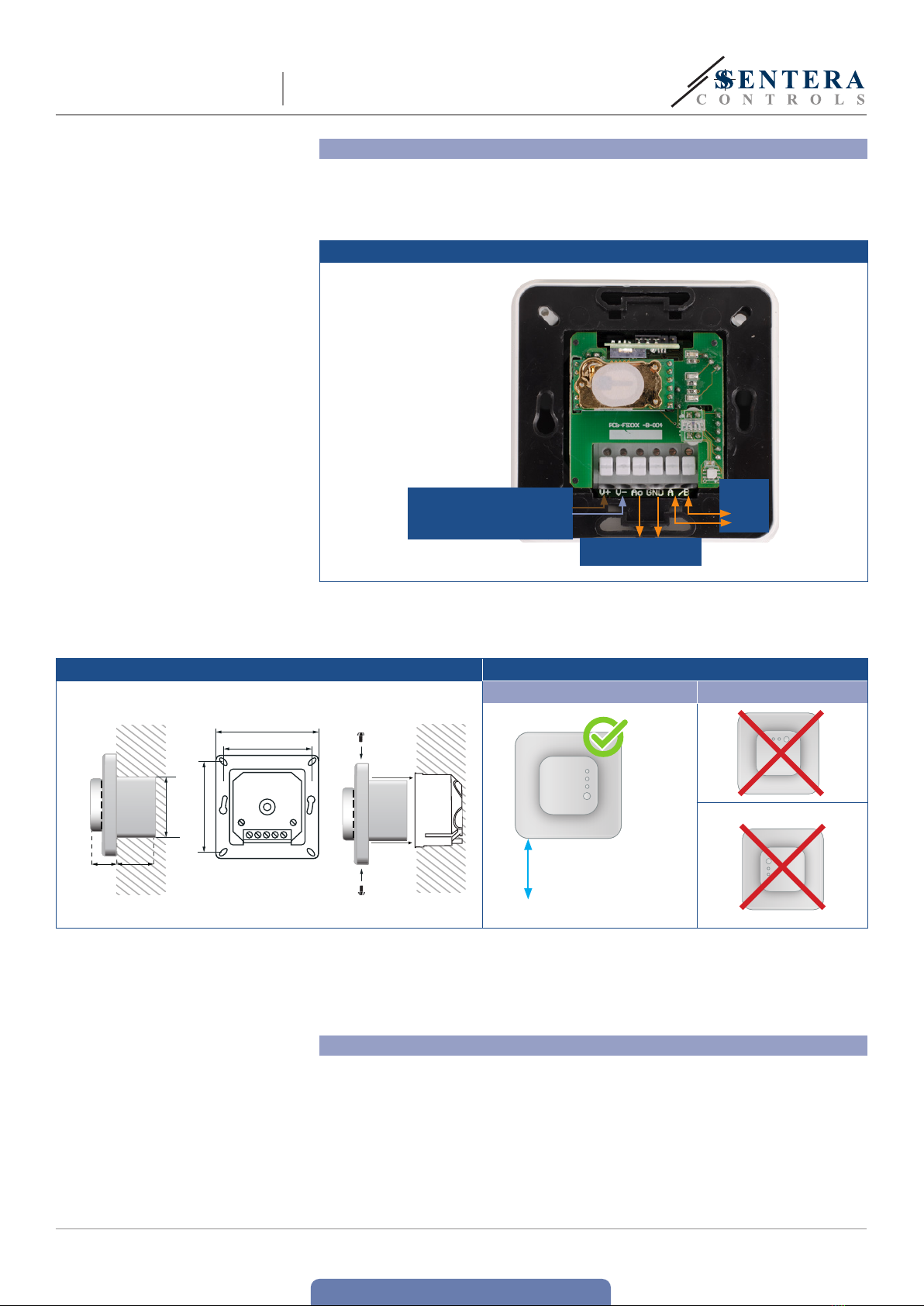
RTU communication. To enter “Boot mode”, put a jumper onto pins 3 and 4 of the P1
header and restart the power supply. One “Boot mode” is activated, the firmware
can be updated via SM Boot application (part of 3SModbius software suite) or
Sensistant.
NOTE Make sure the power supply does not get interrupted during “bootload” procedure,
otherwise you risk losing unsaved data.
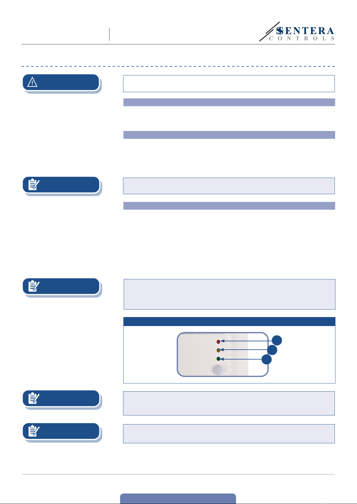
LED indications and audible alarm module:
1. When the green LED is on, the measured value (temperature, relative humidity or
CO2) is between the minimum and maximum alert range values (Fig. 6 - 1). In this
case the audible alarm is OFF.
2. When the yellow LED is on, the measured value (temperature, relative humidity
or CO2) is in the alert range (Fig. 6 - 2). In this case the audible alarm is ON.
3. When the red LED is on, the measured value (temperature, relative humidity or
CO2) is below the minimum measurement range value or above the maximum
value. In this case the audible alarm is OFF. Blinking red LED indicates loss of
communication with the sensor (Fig. 6 - 3).
NOTE e audible alarm output can be set via Holding register 78. By writing 0 in Holding
register 78, the audible alarm will be disabled. By default, the audible alarm
function is set to “continuous”. By writing 2 in Holding resister 78, the audible
alarm will change to “pulsed”.
Fig. 6 LED indications
3
2
1
NOTE By default, the LED indication refers to CO2measurements. is can be changed to
temperature or relative humidity values via Modbus Holding Register 79 (see Table
Holding registers below).
NOTE e intensity of the green LED can be adjusted between 0 and 100 % with step of
10 % according to the value set in Holding register 80.

www.sentera.eu
MIW-FCMFXB-R-EN-000-19/02/2021 10 - 10
back to the table of contents
FCMFXB-R INTELLIGENT CO2SENSOR WITH
BUZZER
Ambient light sensor
e measured light intensity in lux is available in Input Register 41. Additionally,
an active and standby level can be defined in Holding registers 35 and 36. Input
Register 42 indicates if the measured value is below standby level, above active
level or in between both levels:
■Ambient light level < standby level: Input Register 42 indicates “Standby”.
■Ambient light level > active level: Input Register 42 indicates “Active”.
■Standby level < Ambient light level < Active level: Input Register 42 indicates “Low
intensity”.
VERIFICATION OF INSTALLATION
After switching on the power supply one of the LEDs lights up according to the
status of the measured variable. If this is not the case, check the connections.
TRANSPORT AND STORAGE
Avoid shocks and extreme conditions; stock in original packing.
WARRANTY AND RESTRICTIONS
Two years from the delivery date against defects in manufacturing. Any modifications
or alterations to the product after the date of publication relieve the manufacturer
of any responsibilities. e manufacturer bears no responsibility for any misprints or
mistakes in this data.
MAINTENANCE
In normal conditions this product is maintenance-free. If soiled, clean with a dry or
damp cloth. In case of heavy pollution, clean with a non-aggressive product. In these
circumstances the unit should be disconnected from the supply. Pay attention that
no fluids enter the unit. Only reconnect it to the supply when it is completelydry.
This manual suits for next models
1
Table of contents
Other Sentera Controls Accessories manuals
Popular Accessories manuals by other brands

Pure-Wave
Pure-Wave Quantum 6600 installation guide

ACU-RITE
ACU-RITE 06002RM/592TXR instruction manual

Silvercrest
Silvercrest SAD 12 C3 operating instructions

Glowworm
Glowworm 20040796 Installation and instructions for use

wattstopper
wattstopper DT-305 installation instructions

Celabs
Celabs DCB101 Specification sheet