RETROAKTIV MPG-70 OWNER’S MANUAL
3
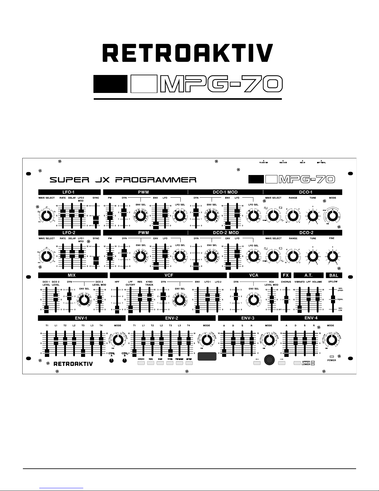
FEATURES:
• MPG-70 can control all of the tone
parameters featured in the Vecoven
firmware upgrade, as well as all of the
44 tone parameters featured on the
classic PG-800.
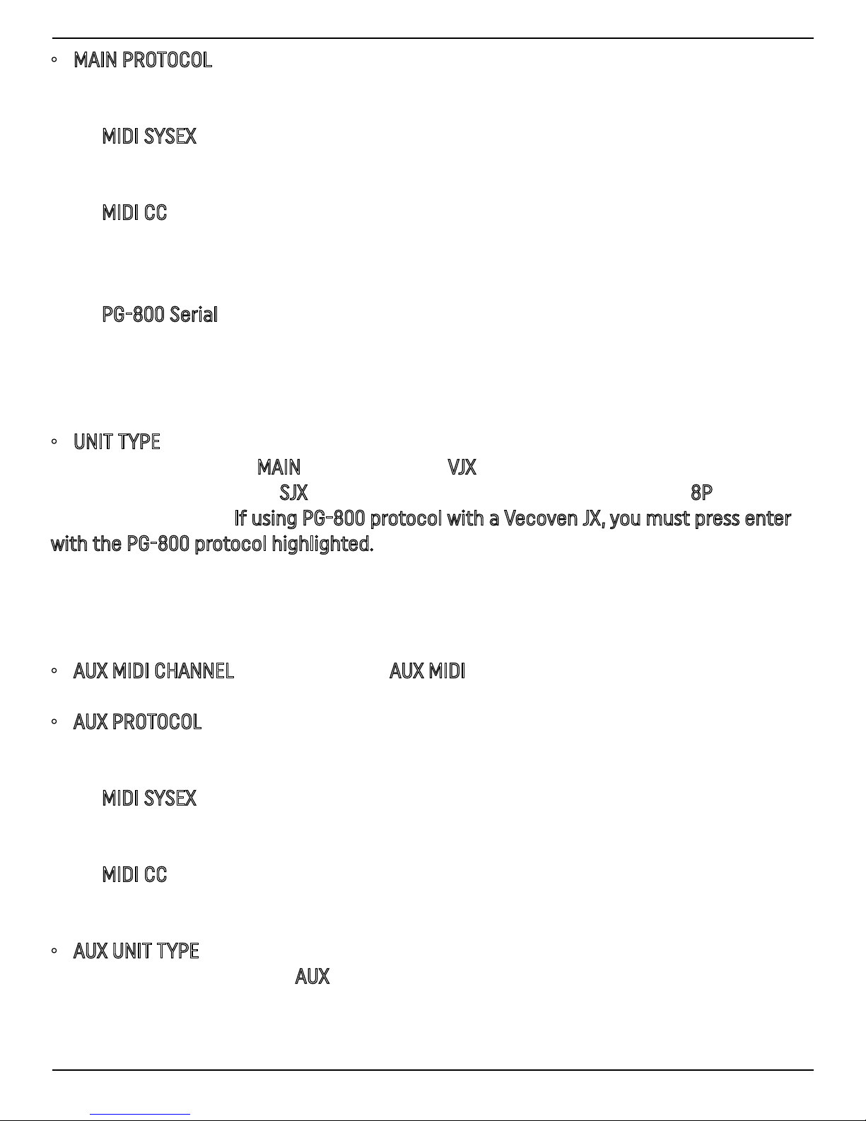
• PG-800 serial communication or
MIDI can be used to communicate with
the Super JX, MKS-70, or JX-8P, allowing
for the MPG-70 to control any stock
or vecoven modified units. MIDI CC,
SYSEX, or PG-800 serial output can be
used to control Vecoven modified JX
units.
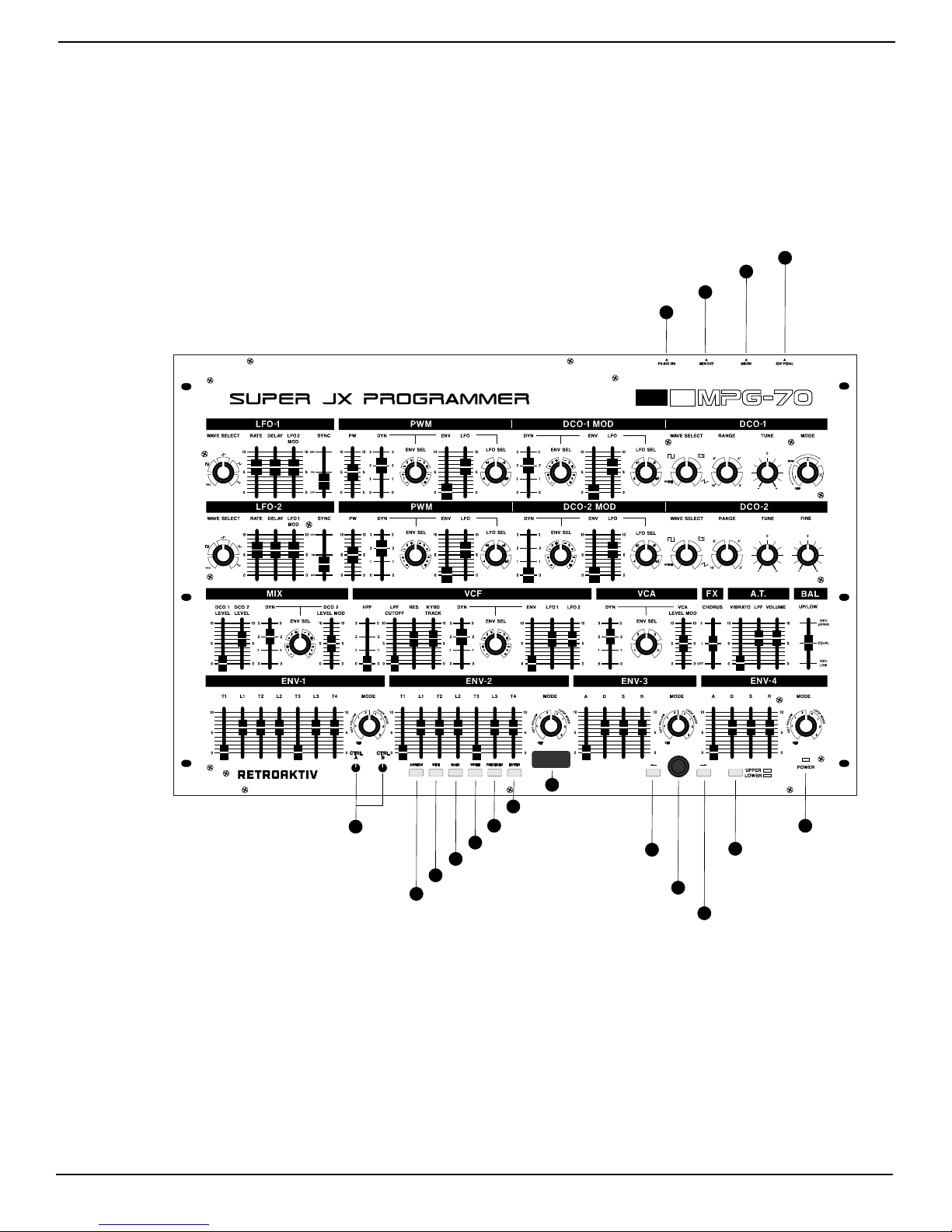
• The programmer features a MAIN
and AUX channel, allowing for multiple
units to be controlled individually or
simultaneously.
• Assignable controllers A, B, and EXP
PEDAL can be programmed to control
up to 5 JX tone parameters simultane-
ously, allowing for more expressive real
time controls of the synthesizer.
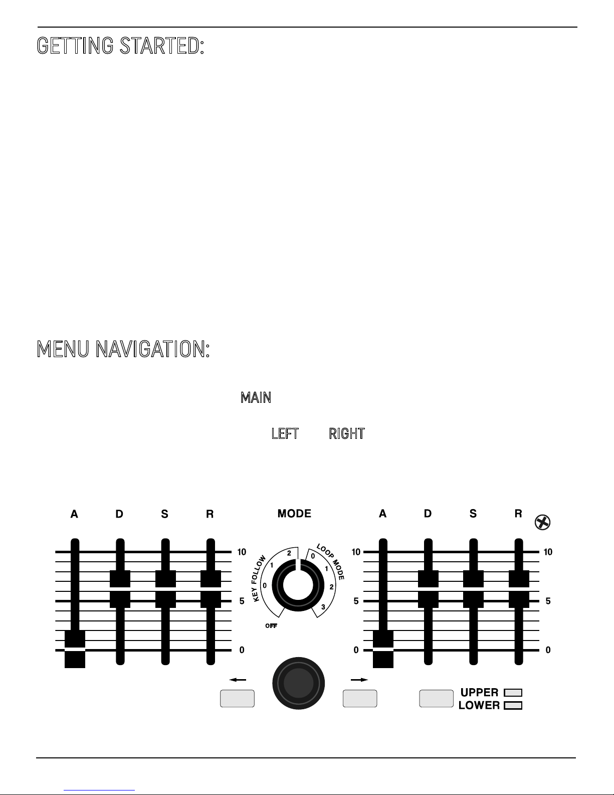
• UPPER and LOWER voices can be
edited individually or simultaneously,
which streamlines the patch creation
process significantly.
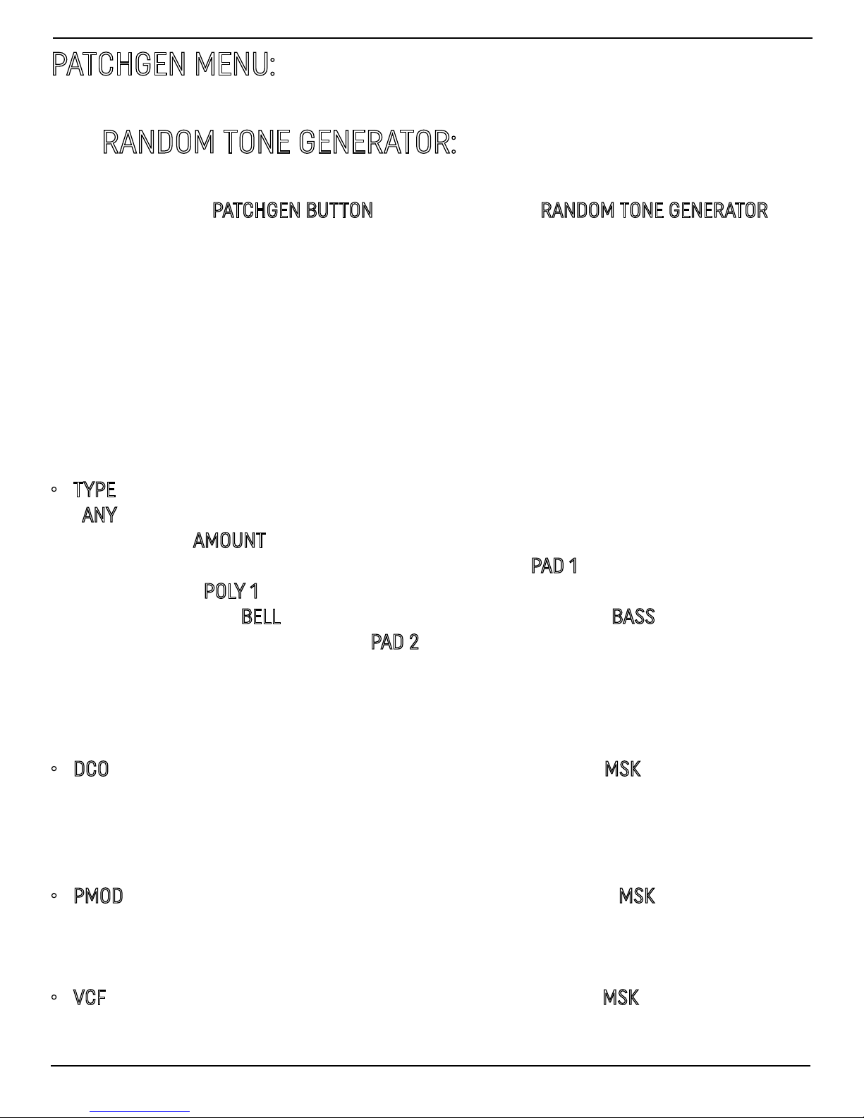
• A full featured RANDOM TONE GEN-
ERATOR allows for quick generation of
new sounds. New tones can be com-
pletely random, or users may select a
tone category such as PAD, POLY, BASS,
BELL/METAL, and COMPLEX. Each sec-
tion of the synth can be masked so
that the RTG will not affect the masked
sections of the synth when generating
a new tone.
• MANUAL and SCRATCH TONE GENER-
ATOR function can transmit the current
position of all sliders, or generate a ba-
sic tone which serves as a basic sta-
ing place when creating a new sound.
SCRATCH TONE GENERATOR can gener-
ate multiple types of tones, including
basic dual DCO, basic LFO pulse width
modulation, and basic SYNC tones.
• ASSIGN A, B, and P, as well as MIDI
seings can be saved as defaults for
quickly recalling preferred seings on
power-up
• Unit features a sloped mixing board
style enclosure making it ideal for set-
ting up on a desktop, or can be mount-
ed in any 19” rack.