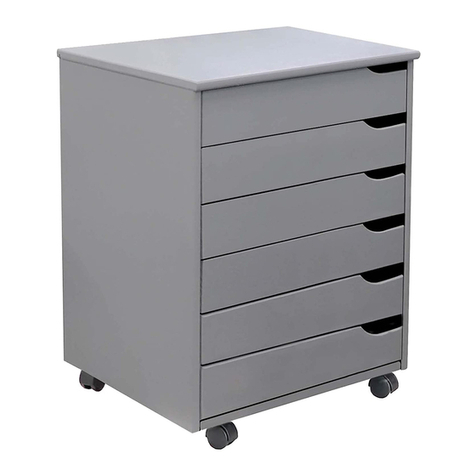
Rev-A-Shelf 5730 Series User manual

INSTALLATION INSTRUCTIONS: 5730/5786 SERIES PULLOUT BASKET WITH SOFT–CLOSE
12400 Earl Jones Way
Louisville, KY 40299
rev-a-shelf.com
Customer Service: 800-626-1126
5730/5786 SERIES PULLOUT BASKET WITH SOFT-CLOSE
TOOLS REQUIRED:
30 MIN
ESTIMATED ASSEMBLY TIME:
CARE AND MAINTENANCE:
Clean with a damp cloth and
wipe parts dry.
I-57XX-0915
A
B
C
DE
Datum point
Bottom dimension
12CR /15CR / 21CR / 30CR / 33CR
210 / 8
9
/
32
”
1
5
/
32
”
40
mm
164
mm
/ 241
mm
/ 393
mm
/ 623
mm
/ 699
mm
D
D
E
F G
A
B
6
1
/
2
”
9
1
/
2
”
15
1
/
2
”
24
17
/
64
”
27
17
/
64
”
H
A
(5730) (5786)
IJ
J
I
Basket (A), Slide (B), Side mount bracket (C), Bottom Mount bracket (D), Logo cap (E), Mounting
bracket (F), Door mounting bracket (G), Double sided tape (H), wood screw (I), Machine screw (J)
PART LIST:
#2 7
64

Customer Service: 800-626-1126 | rev-a-shelf.com
2
A
B
C
DE
Datum point
Bottom dimension
12CR /15CR / 21CR / 30CR / 33CR
210 / 8
9
/
32
”
1
5
/
32
”
40
mm
164
mm
/ 241
mm
/ 393
mm
/ 623
mm
/ 699
mm
D
D
E
F G
A
B
6
1
/
2
”
9
1
/
2
”
15
1
/
2
”
24
17
/
64
”
27
17
/
64
”
H
A
(5730) (5786)
IJ
J
I
Attach bottom-mount brackets
to front and rear of each slide
with two screws per bracket.
Front bracket should use the
fourth and sixth top hole from
the front of the slide. The back
brackets use the third and fth
top holes from the rear of the
slide.
Mark the four hole locations
on cabinet oor per Bottom
Dimension Diagram. Align
bottom bracket holes with
marked locations and install
with four screws.
NOTE
If door mounting, skip to door
mount instructions.
STEP 1
Snap the two logo caps to the
studs on the front side of the
basket.
Place basket on top of slides and
push back until the basket locks
under the tab at the rear and the
button on the side.
NOTE
You should hear the button click
when engaged.
STEP 2
Bottom Mounted:
A
B
C
DE
Datum point
Bottom dimension
12CR /15CR / 21CR / 30CR / 33CR
210 / 8
9
/
32
”
1
5
/
32
”
40
mm
164
mm
/ 241
mm
/ 393
mm
/ 623
mm
/ 699
mm
D
D
E
F G
A
B
6
1
/
2
”
9
1
/
2
”
15
1
/
2
”
24
17
/
64
”
27
17
/
64
”
H
A
(5730) (5786)
IJ
J
I
A
B
C
DE
Datum point
Bottom dimension
12CR /15CR / 21CR / 30CR / 33CR
210 / 8
9
/
32
”
1
5
/
32
”
40
mm
164
mm
/ 241
mm
/ 393
mm
/ 623
mm
/ 699
mm
D
D
E
F G
A
B
6
1
/
2
”
9
1
/
2
”
15
1
/
2
”
24
17
/
64
”
27
17
/
64
”
H
A
(5730) (5786)
IJ
J
I
A
B
C
DE
Datum point
Bottom dimension
12CR /15CR / 21CR / 30CR / 33CR
210 / 8
9
/
32
”
1
5
/
32
”
40
mm
164
mm
/ 241
mm
/ 393
mm
/ 623
mm
/ 699
mm
D
D
E
F G
A
B
6
1
/
2
”
9
1
/
2
”
15
1
/
2
”
24
17
/
64
”
27
17
/
64
”
H
A
(5730) (5786)
IJ
J
I
A
B
C
DE
Datum point
Bottom dimension
12CR /15CR / 21CR / 30CR / 33CR
210 / 8
9
/
32
”
1
5
/
32
”
40
mm
164mm / 241mm / 393mm / 623mm / 699mm
D
D
E
F G
A
B
6
1
/
2
”
9
1
/
2
”
15
1
/
2
”
24
17
/
64
”
27
17
/
64
”
H
A
(5730) (5786)
IJ
J
I
I-57XX-0915

3INSTALLATION INSTRUCTIONS: 5730/5786 SERIES PULLOUT BASKET WITH SOFT–CLOSE
A
B
C
DE
Datum point
Bottom dimension
12CR /15CR / 21CR / 30CR / 33CR
210 / 8
9
/
32
”
1
5
/
32
”
40
mm
164
mm
/ 241
mm
/ 393
mm
/ 623
mm
/ 699
mm
D
D
E
F G
A
B
6
1
/
2
”
9
1
/
2
”
15
1
/
2
”
24
17
/
64
”
27
17
/
64
”
H
A
(5730) (5786)
IJ
J
I
Attach slide half of side-mount
bracket to front of slide with two
screws per slide. Front screw
should use the fourth top hole
from the front of the slide.
Mark fourth hole locations
on cabinet wall per Flank
Dimension Diagram. Align
cabinet half of side-mount
bracket holes with marked
locations and install with four
screws. Repeat on opposite wall.
Place slide assembly on top of
cabinet mount bracket, insert
screws, adjust to the desired
width of basket and tighten
screws. Repeat on opposite wall.
NOTE
If door mounting, skip to door
mount instructions.
For Inset-Door applications,
move the side-mount bracket
back the thickness of the door.
OPTIONAL MOUNTING
Flip the two brackets to make an
“S”shape to avoid door hinges
or for additional space
STEP 1
Snap two logo caps to the studs
on the front side of the basket.
Place basket on top of slides and
push back until the basket locks
under the tab at the rear and the
button on the side.
NOTE
You should hear the button click
when engaged.
STEP 2
A
B
C
DE
Datum point
Bottom dimension
12CR /15CR / 21CR / 30CR / 33CR
210 / 8
9
/
32
”
1
5
/
32
”
40
mm
164mm / 241mm / 393mm / 623mm / 699mm
D
D
E
F G
A
B
6
1
/
2
”
9
1
/
2
”
15
1
/
2
”
24
17
/
64
”
27
17
/
64
”
H
A
(5730) (5786)
IJ
J
I
Side Mounted:
For Face-Frame Cabinets
Front Back
38
mm
min1
49/64
”
88
mm
64mm 64
mm
B
C
C
A
Flank Dimension
E
11/2”217/64”31/2”217/64”
45mm
J
I
J
* Add door thickness
for Inset cabinets
Front Back
38
mm
min1
49
/
64
”
88mm
64
mm
64mm
B
C
C
A
Flank Dimension
E
1
1
/
2
”2
17
/
64
”3
1
/
2
”2
17
/
64
”
45
mm
J
I
J
Front Back
38
mm
min149
/
64”
88mm
64
mm
64
mm
B
C
C
A
Flank Dimension
E
1
1
/
2
”2
17
/
64
”3
1
/
2
”2
17
/
64
”
45
mm
J
I
J
Front Back
38
mm
min149
/
64”
88
mm
64
mm
64
mm
B
C
C
A
Flank Dimension
E
1
1
/
2
”2
17
/
64
”3
1
/
2
”2
17
/
64
”
45
mm
J
I
J
Note: Inside cabinet widths can be as follows:
12CR = 1311/32” [339mm] – 13.68” [348mm]
15CR = 1611/32” [415mm] – 16.68” [424mm]
21CR = 2211/32” [567mm] – 22.68” [576mm]
30CR = 3125/64” [797mm] – 31.73” [806mm]
33CR = 343/8” [873mm] – 34.72” [882mm]
I-57XX-0915

Customer Service: 800-626-1126 | rev-a-shelf.com
4
12400 Earl Jones Way
Louisville, KY 40299
rev-a-shelf.com
Customer Service: 800-626-1126
Attach slide half of side mount
bracket to front of slide with two
screws per slide. Front screw
should use the fourth top hole
from the front of the slide.
Snap two logo caps to the studs
on the front side of the basket
Place basket on top of slides and
push back until the basket locks
under the tab at the rear and the
button on the side.
NOTE
You should hear the button click
when engaged.
STEP1
Attach slide mount bracket to
slide with two screws per slide.
Insert Door Mounting Bracket
between screws and Mounting
Bracket. Tighten screws. Repeat
for opposite side.
NOTE
Door Mounting Bracket should
face towards outside of basket.
Place basket on top of slides and
push back until the basket locks
under the tab at the rear and the
button on the side
NOTE
You should here the button click
when engaged.
Apply double stick tape to the
Door Mounting Brackets. Align
cabinet door to surrounding
doors/drawers and press against
brackets.
Slowly pull unit open and install
four screws per bracket into
door.
STEP 1
Side Mounted Without Brackets:
Frameless cabinets and scabbed Face Frame cabinets only
Door Mounted
Front Back
35mm
min1
49
/
64
”
160
mm
32mm
32mm
B
1
C
A
Wall Dimension
E
1
25
/
64
”1
17
/
64
”6
5
/
16
”1
17
/
64
”
45
mm
J
Front Back
35
mm
min1
49
/
64
”
160
mm
32
mm
32mm
B
1
C
A
Wall Dimension
E
1
25
/
64
”1
17
/
64
”6
5
/
16
”1
17
/
64
”
45
mm
J
Front Back
35mm
min1
49
/
64
”
160
mm
32
mm
32
mm
B
1
C
A
Wall Dimension
E
1
25
/
64
”1
17
/
64
”6
5
/
16
”1
17
/
64
”
45
mm
J
Front Back
38
mm
min1
49/64
”
88
mm
64mm 64
mm
B
C
C
A
Flank Dimension
E
11/2”217/64”31/2”217/64”
45
mm
J
I
J
E
A
G
F
G
H
H
H
J
I
E
A
G
F
G
H
H
H
J
I
E
A
G
F
G
H
H
H
J
I
E
A
G
F
G
H
H
H
J
I
E
A
G
F
G
H
H
H
J
I
Note: Inside cabinet widths must be:
12CR = 115/16” [287mm]
15CR = 145/16” [364mm]
21CR = 205/16” [516mm]
30CR = 293/8” [746mm]
33CR = 323/8” [822mm]
I-57XX-0915
Other manuals for 5730 Series
1
This manual suits for next models
1
Other Rev-A-Shelf LCD Drawer manuals
