Revo DCZ-200-GS User manual

ThankyouforyourkindpatronagetoREVOBypurchasingREVODCZ-200-
GSHighSpeedSelfLubricatedOverlockSewingMachine.
We are sure by installation of this machine in your workshop, you can get
relief from your repeated troubles caused by the out-dated models of
Overlockmachinesbeingusedbyyou.
Furthermoreitwillmakewonderfulcontribution,certainlytotheproductivity
whenthemachineisoperatedappropriately.
To acquainte the users with proper operation adjustment and maintenance
aboutthismachineweareprovidingthisInstruction-Manual.
HeartilywishingyousuccessfulservicebyREVODCZ.
INTRODUCTION

SPECIFICATION
Name : HighSpeedOverlockedStitchSewingMachine
Dimensions : 350x225x285mm.
Weight : 21 Kgs
Construction : Dust-Proof, Oil-tight,Enclosedcompletely.
Stitchtype : Overedge seaming
SewingSpeed : upto6,500 s.p.m.
Stitchesperinch : 6-20stitchesperinch,7-23.5stitchesper30mm
Use : OveredgeSeaming, BlindHemmingandotherusesongeneralorknittedmaterials.
WidthofOveredgeSeam : 3-4mm,Standardand2-8mmisavailablebyexchangeofnecessaryGaugeParts.
StrokeofNeedle : 25 mm.
Needles : DC x1size9to18
AdjustingofFeeding : ExchangeofEccentrics.
KnivesforFabricCutting : LowerKnife-MadeofSpecialSteelFlattype.UpperKnife-MadeofSuperHardAlloy.
Lubrication : ForceFeedingbygearpumpandpressureregulatingvalve,andSplashedOilisalso
utilized.
Lubricant : Use H.P.'sTURBINOL-46,CASTROL'sPERFECTOT-46oranyequipmentLubricant.
KeepOiluptoMaximumLevelmarkedintheoilIndicator.
ChangetheentireOilafterThreeMonthsor1000workinghourswhichmaybeachieved
earlier.
CapacityofReservoir : ONE LITRE

INSTALLATION
Fix Supporting Board to the Table by Bolts and Nuts, on which the Rubber Cushion Holder Plate shall be fixed by Wood
Screws. $ Rubber Cushions must be put exactly into each horrow on the plate when settiing machine.
-
Machine Table
Supporting Board
-- Fixing --
-- Fitting of Belt Cover--
-- Dimensions for Semi-submerged Installation --
A
B
C
230
106
60
20
10
45
35
135
40 20
200
175
214
100
10
20
70
260
10
DD
55
280
365
Operator
200
105
4-15
16
4-7.9
Section D-D
1

SEWINGSPEEDANDTURNINGDIRECTION OFPULLEY
However the available highest sewing speed is 6,500 s.p.m., from the view point
of durability of machines, it is preferable to operate at the economical speed of
6,000 s.p.m. after the initial operation at 5,000 s.p.m. in 200 hours
approximately--onemonth.
LUBRICATION
Lubricant.
CASTROL'SPERFELTDT-46isrecommendable.
FeedingofOil
At the time of Despatch, the oil will have been drained completely from the
machine, So, it should be filled with Clean Oil to the Upper line of Oil Gauge (A)
removingScrewat themark"OIL"
Note : At the beginning of operation of brand-new machines or the re-use of
machines rested long time, Clean Oil must be fed around Needle Guard and
UpperLooperBaradditionally.
OilGaugeandConfirmationofOilFlow
CheckOil Guardeveryday beforeoperationreplenishcleanoilifthesurfaceof oil
is below the under line. At the beginning of operation, confirm that the oil is
flowingsmoothlyoutofOilSightNozzle(B)insidemachine.
ExchangeofOil
To keep the machine's life long time, oil for new machine must be exchanged
completely with new one after the initial operation of about 250 hours, And, after
theabove,itmustbeexchangedin2-3timeseveryyear,ExchangeofOil shallbe
madeaccordingtothefollowingorder.
(1) RemoveV-BeltfromMotorPulleyandtakeoutmachine-headtotopfaceof
theTable.
(2) RemoveBeltCover(A)
(3) DraintheOilfrommachinelooseningDrainHoleScrew(B)and(C)
A
SF. OIL
B
A
B
C
2

CleaningofFilterScreens
Everytime when the oil is exchanged, the inside of Base and Filter Screens should
becleanedremovingtheBase.
To remove the Base, take out 4 Pcs. of its Screws after draining Oil and turning
machineheadover.
After cleaning, make Base and its Gasket be as they were before and screws shall
betightenedexactly.
FITTINGOFNEEDLE
Please remember that groove of needle should face always to the back side of
machines.
FITTINGORDER:
(1) TurnPulleyuntiltheneedlecomestoitshighestposition.
(2) RaisePresserfootReleaseLever(A)tothedirectionshowedbyarrow,and
swingPresserFoot (B)outsideways.
(3) InsertNeedleintoNeedleBarasfarasitwillgolooseningNeedle
ClampingNut(C),thentightentheNutagain.Atthismomentthegrooveof
needleshouldfacetothebacksideofmachineasstatedabove.
THREADING
Threadingmustbemadecorrectlyaccordingtofiguresshowed hereinafter.
Incaseof1Needle, 3thread:
A Needlethread.
B UpperLooperthread.
C LowerLooperthread.
Drain HoleScrewforInner(B)...fordrainingOilinsideFrame.
DrainHoleScrewforOuter(C)fordrainingoilcollectedintheOpeningspacebetweenbetweenframeandbodyofthe
machine.
(4) Screw(B)and(C)mustbere-tightenedafterdraining.
(5) FeedingofnewOil.....
C
A
B
Filter
Screen
Base
Filter Screen
3

Position of Needle Thread Eyelet must be changed in case of blind hemming.
Refer to "Needle thread Tension" on page 9 please.
In case of 1 Needle 2 thread with spreader
A Needle Thread
B Lower Looper thread.
THREAD TENSION
Tension of thread should be adjusted as loosely as possible unless the good balance is lost in the seaming.
Stronger tension beyond necessity may cause the thread-breakage or skip-stitching.
Note: Refer to items regarding to the thread tension in "Proper Adjustments" on page 9 please.
Pressure of Presser Foot
The pressure of Presser Foot should be adjusted most weakly so far as presser Foot can act properly.
However the uniformity in the feeding and seaming will be lacked if the pressure is weak excessively.
The pressure shall be strengthened when turning Adjusting Screw (C) to the direction (A) and weakened turning to (B) to
the contrary.
PressureofPresserFoot
Thepressureof PresserFoot shouldbeadjusted mostweaklyso faras presserFoot
canactproperly.
Howevertheuniformityinthe feedingand seamingwillbelackedif thepressure is
weakexcessively.
The pressure shall be strengthened when turning Adjusting Screw (C) to the
direction(A)andweakenedturningto(B)tothecontrary.
A
B
C
(for Blind-Hemming Stitch)
A
B C
- - - - (for Wooly Tread)
4

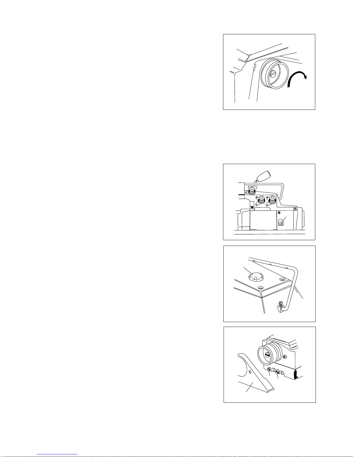
ADJUSTING OF FOOT LIFTER LEVER
Adjust Pressure Foot to Start to lift from the top face of stitch Plate turning
Adjusting Screw (E) when the Foot Lifter Lever (F) is lowered in 3 mm from the
end of Adjusting Screw (E) for Foot Lifter Lever Stopper (D). When Presser Foot
is raised to its highest position, adjust the bottom face of it to be 4mm. from top
face of Stitch Plate.
At this moment Loosen Nut (I) and turn Stop Screw for Presser Foot (H) then
adjust the Screw to touch with Arm of the machine.
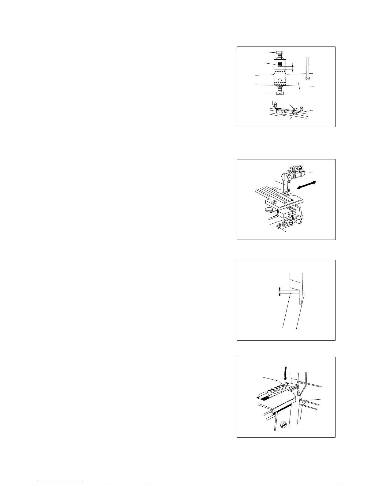
ADJUSTING OF WIDTH OF OVEREDGE SEAM
Towidenthewidth;
Loosen Screw (A) for upper Knife Holder and move the Holder to the
Direction (X) According to the necessity and tighten Screw (A) again.
Subsequently loosen Screw (B) for Lower Knife Holder. Then Lower Knife
Holder will move to the direction (X) by pressure of the spring inside,
consequentlyLowerKnifewilladherecloselytoUpperKnife(D)withsuitable
strength.And,tightenScrew(B)again.]
Tonarrowthewidth
Loosen Screw (B) for Lower Knife Holder and Move the Holder to the
direction (Y) according to the necessity and tighten Screw (B) softly.
Subsequently,loosenScrew(B)forLowerKnifeagainandmadeLowerKnife
(C) adhere closely to Upper Knife (D) by the pressure of spring. Then,
retightenScrew(B).
Note : For adjusting width of the overedge seam, make the blade of Upper
KnifebehigherthanifofLowerKnifein0-1mm.
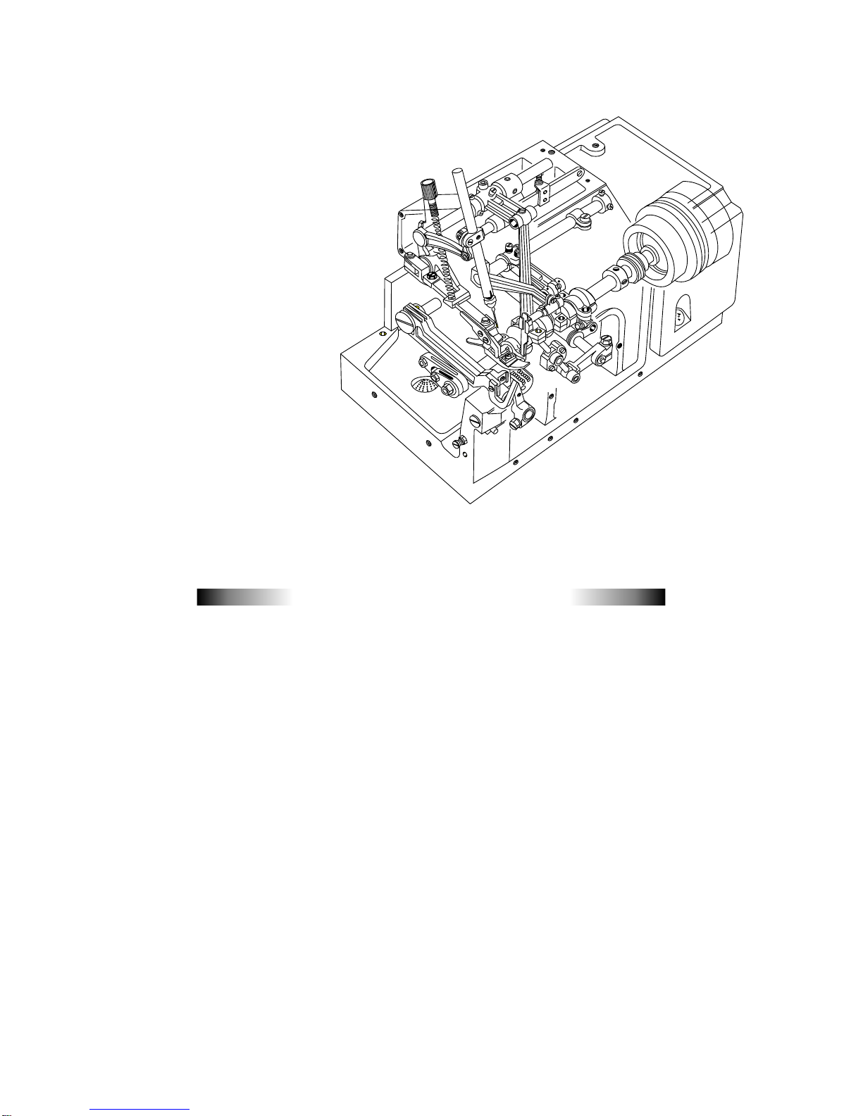
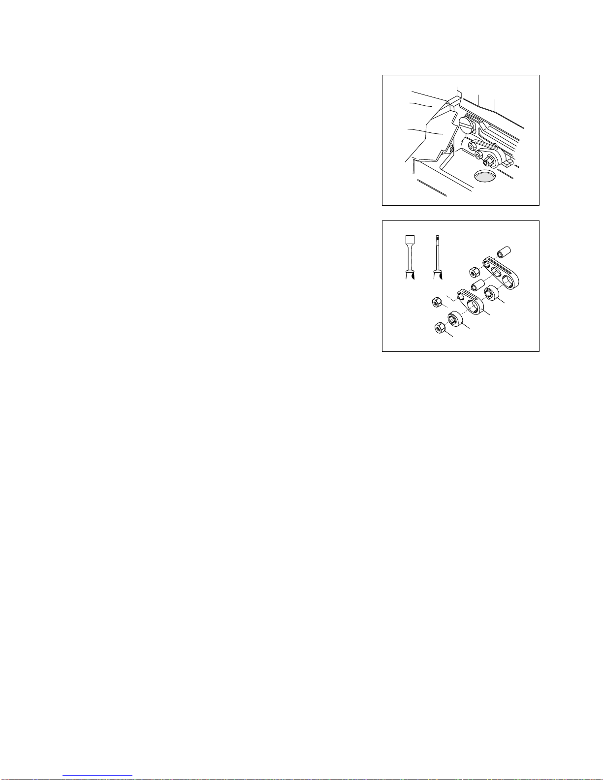
SharpnessofKnives
Check the sharpness of knives turning Pulley manually with a thread put
between Upper and Lower Knives, after adjusting the seam of overedge
seam.
Note : When it may be necessary to sharpen knives please refer to
"SharpeningofknivesforFabricCutting"onPage14.
(1)
(2)
(3)
0 ~ 1mm
I
E
D
G F
H
3mm
Thread
A
B
C
Y
X
D
5

Main Feed Driving Eccentric (G) can be exchanged by the same manner stated as above, after removal of Nut (E) and (H)
DifferentialFeedBarDrivingConnector(L)
In case of exchange of Eccentrics, from which dust and rubbish should be removed washing, by oil. And, assemble them
makingtheirsteppedpartfaceoutside.
When Eccentric is smaller number than the one of "G" side is used at (C) side, the seam to be obtained will have a touch of
loose.
ADJUSTINGOFSTITCHLENGTH
By the exchange of Feed Driving Eccentrics, stitch length is adjusted, Each
Eccentric has a stamp showing Stitch numbers per inch. (25.4 mm) However,
please pay your attention to the fact that there will be difference in some measure
owingtokindorthicknessoffabricsandratioofdifferentialfeeding.
TheillustrationshowstheviewofmachinesetwithFeeddrivingEccentrics.
The Stitch Length shall be changed opening Cloth Plate (Upper) (A) and Feed
MechanismCover(B).
The illustration shows the condition removed Eccentrics and also Socket Wrench
andEccentricExtractor.ToExchangeDifferentialFeedDrivingEccentriconly.
RemoveNut"E"bySocketWrench(D)
RemovetheEccentricbyExtractor(F)Screwedintoitshole.
After,putEccentricatneed,andtightenNut"E"Asbefore.
A
B
D F
H
E C
L
G
6

Y 5 5 6 3 2 8 2 1
Y 6 6 7 3 2 8 2 2
Y 7 7 8 3 2 8 2 5
Y 8 8 9 3 2 8 2 3
Y 9 9 10.5 3 2 8 2 4
Y 1010 12 3 2 8 2 4
Y 11 11 13 3 2 8 2 4
Y 12 12 14 3 2 8 2 4
Y 13 13 15 3 2 8 2 4
Y 14 14 16.5 3 2 8 2 4
Y 15 15 18 3 2 8 2 4
Y 16 16 19 3 2 8 2 4
Y 17 17 20 3 2 8 2 4
Y 18 18 21 3 2 8 2 4
Y 19 19 22 3 2 8 2 4
Y 20 20 23.5 3 2 8 2 4
Y 22 22 26 3 2 8 2 4
Y 24 24 28 3 2 8 2 4
Y 26 26 31 3 2 8 2 4
Y 28 28 33 3 2 8 2 4
Y 30 30 35.5 3 2 8 2 4
Y 40 40 47 3 2 8 2 4
Y 50 50 59 3 2 8 2 4
Y 70 70 83 3 2 8 2 4
Y 100 100 118 3 2 8 2 4
Kind of Feed Driving Eccentrics
No. (Stamped) Stitches per inch Stitches per 30 mm. Parts No.
7

PROPERADJUSTMENT
(1)TENSIONOFNEEDLETHREAD
LooseningScrew(A)andliftuptheEyelet(B)for
tighteningofneedlethread,andlowertheEyelettoloosentothecontrary.
Ingeneraloverseaming,makeunderline ofEyelet(B)fitscrew(A)as thestandard
manner.
In blind hemming, two threads with spreader, make upper-line of Eyelet fit Screw
(A)
(2) TENSIONOFLOWERLOOPERTHREAD
MoveEyelet(C) tothedirection (F)whenit needstotighten thisthreadonly, and to
loosen it move Eyelet to the direction (E) loosening Screw (D). On the other hand,
when Looper Thread Pull-off (G) is moved to direction (F) both of upper and lower
looperthreadsaretightened,andtodirection((E)tobeloosened.
Such being the case, adjusting should be made in consideration of the goods
balanceofthreadtension.
(3)TENSIONOFUPPERLOOPERTHREAD
When it needs to tighten Upper Looper thread only, move upper Looper Thread
Eyelet (J) to the direction (K). To the contrary, for loosening of the said thread
loosenScrew(I)andmoveEyelet(J)tothedirection(L)
ADJUSTINGOFDIFFERENTIALFEEDING
On machines with mark "D" on model plates, adjusting of normal differential feeding (Shrink Sewing) can be made by
exchangeandcombinationofeccentrics.
At the sewing to increase the effectiveness of differential feeding by exchange of eccentrics turn Pulley manually and confirm
thatdifferentialFeedDogwillnottouchwithMainFeedingDogandStitchPlatebeforetheoperation.
A
B
C
F
G E D H
J
K
L
I
8

Whenwoolythreadisused:-
Incasesuchthreadwhichhasaplentyelasticityisused,threadingofUpperLooper
Threadshouldbechangedaccordingtodottedlineontheillustration(Right)
Note : When it is returned to of ordinary thread after the sewing of wooly thread,
donot,forgetthatthethreadingmustbechangedasitwas.
(4)HEIGHTOFNEEDLE
When the Needle reaches to its highest position, there should be the distance of
9.5to10.0mmbetweenneedlepointandtopfaceofStitchplate.
(But11.5-12.0mmforDCZ-202)
To adjust the above distance turn the Pulley and make needle be at its highest
position and then loosen screw (A) for the Needle Bar Connection Bracket which
canbeseenthroughNeedleBarConnectingLinkCover.
(4)TIMINGBETWEENNEEDLEANDUPPERLOOPER
Insert the Upper Looper to its Looper Bar(B) at the deepest, then tighten Screw (C)
forthetimebeing.
When needle begins to descend and pass in back of Upper Looper, make Upper
Looper be close to Needle but without touch. And tighten Screw (C). And, when
Upper looper reaches to the left end of its movement, the distance between Center
ofNeedleandthepointoftheLoopermustbe5-6mm.
To re-adjust the distance stated above, open Front Cover and remove the Looper
thread Eyelet Supporter (D) and then loosen Screw (F) for Upper Looper Bar
DrivingArm(E)
Note:AtthetighteningofScrew(F),caremustbetakentomakeUpperLooperBar
DrivingArm(E)nottomoveinfrontortheRear.
C
B
5 ~6mm
D
E
F
A
9.5~
10mm
9

(6)TIMINGBETWEENUPPERANDLOWERLOOPERS
At the rendesvous of Upper and Lower Loopers (A,B) the point Upper Looper
passes through the depression just under swelling part on back face of the Lower
Looper.
Itshould beadjustedtobeless than0.2mmforallowanceof UpperLooperagainst
thebackfaceofLowerLooper,andalsoagainstitsswellingpart.
To obtain this allowance, adjust the positioning of Lower Looper in front-rear
looseningitsScrew(C)
Note:Aftertheadjusting,Screw(C)shallbetightened.Butcaremustbegiventoits
tightness not to be too strong because the adjusting of Lower Looper in right-left is
alsonecessary.
(7)TIMINGBETWEENNEEDLEANDLOWERLOOPER
Distance between point of Lower Looper and Center of Needle must be 3-4mm.
whenLoopercomestotheleftendofitsmovement.
To obtain the distance mentioned above, Screw (C) for Lower Looper Holder will
beloosenedtoadjustlowerLooperinrightandleft.
As for machines of Heavy Duty, the above-mentioned distance shall be
6.5/7.5mm.
(8)POSITIONINGORNEEDLEANDLOWERLOOPERINFRONT-REAR
RELATION
As Closely as possible but without touch, the point of Lower Looper must pass
behind of the Needle which is going up, and at this moment the distance between
themshallbe0.05-0.1mmingeneralcase.
Tomakethisadjusting,Screw(D)willbelossloosened.
0.2mm
0.2mm
A
B
C
3~4mm
C
0.05~0.1mm
D
10

(9) NEEDLE AND NEEDLE GUARDS
(a)
(b)
(10) SETTING AND REMOVAL OF FEED DOGS
By Screw (B) setting and removal of Differential Feed Dog (A) shall be made
and by Screw (D) for main Feed Dog (C)
Auxiliary Feed Dog (E) will be removed loosening Screw (D) and (F) because it
is used fitting to Main Feed Dog (C).
(11) INCLINATION AND HEIGHT OF FEED DOGS
Both top face of Feed Dog (A) and (C) must be at the same height, and run
parallel with the surface of Stich Plate. Which is the standard condition of
Inclination of Feed Dogs.
When Feed Dogs are at their highest position adjust the last second edge of
Main Feed Dog (C) to be at 1mm. approximately higher than the top face of
Stitch Plate.
This adjusting shall be made loosening Screws (B,D)
Auxiliary Feed Dog (E) must be fitted at 1-1.5mm lower than Main Feed Dog
(C)
0~
0.05mm
A
B C
1mm
C A
Stich
plate
0.2mm
D
E
C
E
F
D
A
B
NeedleandNeedleGuard(Rear):
When the Needle which is ascending meets Lower Looper, adjust the
allowancewithNeedleGuard(Rear)(A)tobe0-0.5mm
The Adjusting of Needles Guard (Rear) should be made by Screw (B) for its
front-Rearandright-left positioningand bylooseningof Screw(C)for High-
lowpositioning.
NeedleandNeedleGuard(Front):
The allowance between Needle and Needle Guard (front) (D) shall be
adjusted according to the thickness of thread in use, which is standard
adjusting.
In general, however, the allowance will be adjusted in 0.2 mm. Loosening
Screw(C).
11

(12)PARALLELISMOFFEEDDOGANDSTITCHPLATE
When it needs to adjust the Parallelism of Feed Dogs and stitch Plate according to
conditionsofthesewing,itsadjustingshallbemadeasfollows:
1) RemoveRearCover(A)
2) RemoveClothPlateUpper(B)
3) RemoveFeedMechanismCover(C)
4) BythehexagonalWrenchKey(Size-1/8")loosenScrew(D)andturnFeed
AdjustingPin(F)bytheScrewDriver(E)andadjusttheparallelism.
5) Afteradjusting,tightenScrew(D)takingcaretobenoallowancebetween
FeedAdjustingPin(F)andFeedBar(G)
6) Assembleinorderof(C),(B)and(A)astheywere before.
(13) ADJUSTINGOFKNIVESFORFABRICCUTTING
HeightofLowerKnife;
Blade(A) ofthisknifebeeven withthetopfaceofStitchingPlate oralittlelower(0-
0.3mm)thanthePlate.
HeightofUpperKnife;
Loosening Screw (C) when this knife reaches to the bottom of its motion, make the
engagementwithLowerKnifebe0.5-1.0mm
F
E
D
C
A
B
0.0.3mm
A
B C
C
0.5
~1mm
12

(14)EXCHANGEOFLOWERKNIFE
Lower Knife can be removed pulling it off downwards after loosening of Screw (B)
TofitnewLowerKnifeorre-sharpenedone,insertitsbladefromtheundersideand
tightenscrew(B)
(15)SHARPENINGOFKNIVES
Upper Knife is needles to be re-shapened about one year, because this knife is
madeofSpecialSuperSteelAlloy.
If sharpness of the cutting becomes blunt during the above period, resharpen
LowerKnifereferringtofiguretotheleftside.
Due to aforementioned reason, it is impossible to re-sharpen Upper Knife by the
ordinary Grinder, therefore, provisional one must be readied
always.
Whenre-sharpening ofUpper Knifebecomes necessary,pleasecontactwithusor
dealerwhosoldthemachinetoyou.
Thefigureshows(Angle)ofUpperKnife.
(16)ADJUSTINGOF2NEEDLE4THREAD,OVERLOCKEDSTITCH
MACHINES
(16-1)FITTINGOFNEEDLES
Bothoftwoneedlesshouldbesetcorrectlyfacingtheirscarfstowardsthebackside
of machines. Needles to be used must be those of same
kind.(SystemDcx1)
7.7
67
18
18 13
1.2
2.2
A
B
13

(16-2) THREADING
(Machines for Light Duties)
It should be made correctly
according to the figure.
A Needle Thread
(Left Needle)
B Needle Thread
(Right Thread)
C Upper Looper
Thread
D Lower Looper
Thread.
(Machines for Heavy Duties)
A Needle Thread
(Left Needle)
B Needle Thread
(Right Thread)
C Upper Looper
Thread
D Lower Looper
Thread.
A B C D
A B C D
-----(for Wooly Thread)
14

(16-3)EXCHANGEOFNEEDLECLAMP
To Exchange Needle Clamp (... in cases of removal of Needle Bar or Exchange of
Needle distance ...) Loosen Screws (B and C) and Pull Needles off, and then turn
Needle Clamp (A) anti-clockwise. Tighten Needle Clamp steadily without any
loosenesstosetit.
Adjusting of Needle and Looper shall be made according to following
orderas"StandardManner"
1) HeightofNeedle
2) NeedleDropping.
3) NeedleandUpperLooper.
4) UpperLooperandLowerLooper
5) NeedleandLowerLooper.
(16-4)HEIGHTOFNEEDLES
When both Needles reach to their highest position, the distance between the left
NeedlePointandthetopfaceStitchPlateshallbe9.5-10mm.
(16-5) ADJUSTINGOFNEEDLEDROPPINGPOINT
SetLowerLooperandStopittemporarily.
And, loosen Screw, (D) for Needle Bar Connecting Bracket and decide dropping
points of Needles making each allowance between their back faces and Lower
Looperpointbejustthesame.
9.5~10mm
D
A B
C
15

(16-6) TIMING BETWEEN NEEDLE AND UPPER LOOPER
(a)
(b)
(16-7) TIMING BETWEEN UPPER AND LOWER LOOPERS
Refer to explanation of the same title on page 11.
(16-8) TIMING BETWEEN NEEDLE AND LOWER LOOPERS
Incaseof2needlemachinebuttheLooperthreadiscaughtbyboth needle.
Insert Upper Looper to Looper Bar (A) at the deepest, and tighten screw
(B)temporally,
WhenNeedlesdescending,passthroughbacksideoftheLooper,tightenthe
LoopercloselytotherightNeedlebyScrew(B)butwithouttouch.
Distance between the center of left Needle and point of Upper Looper must
be5-6mm.whentheLooperreachestotheleftendofitsmovement.
Toadjusttheabovedistance:-
OpenFrontCoverandremoveLooperThreadeyeletSupporter(D)
LoosenScrew(F)forUpperLooperBarDrivingArm(E)bytheWrenchofsize
5/16.
In case of 2 Needle machines but the Looper, thread is caught only by the
rightneedle.
Fitting manner of Upper Looper and its relation to Needle are not different
from(a)
But, When Upper Looper comes to the left, make thread eye of the looper
point be at the center between two needles because the looper thread is
caughtonlybytherightoneamongtwoneedles.
DistancebetweencentreofNeedleandthepointofLowerLoopermustbe3-
4mm.whentheLoopercomestotheleftendofitsmovement.
To obtain the distance mentioned above, screw (A) for Lower Looper Holder
will be loosened to adjust the Looper in right and the left.
D
E
F
C
B
5 ~6mm
3~4mm
A
B
A
5 ~6mm
16

(17) USEOFGUIDEANDOTHERATTACHMENTS:
BLINDHEMMINGMACHINE(DCZ-200)
TurningtheAdjustingScrewclockwise.GuideHolderwillcomeuptotheleftanddepth
of the seaming line becomes smaller. To the Contrary, turning it anti-clockwise the
depth shall be bigger. Therefore, the adjusting must be made according to nature of
materialsinuse.TightenStopperScrew(C)aftertheadjusting.
adjusting.
It is preferable that the allowance between Hemming Guide (E) and Guide Holder will
havethespacejustforasheetoffabric.
And, make the point of Hemming Guide (E) come to the halfway on thickness of the
GuideHolder.
Blind Hemming Guide is assembled on DCZ - 200 machines as the "Standard
Equipment".
Tightening Screw (B), Guide shall be fitted to Stitch Plate Supporter just
underneathofClothPlate(Upper)(A)
In the blind hemming, depth of seaming line can be adjusted turning Adjusting
Screw(D)afterlooseningofStopperScrew(C).
To adjust width of the blind hemming, move the guide (viny1 made ) of
HemmingGuide(E)inright-leftlooseningtheScrew(F)
D
C
AB
E
F
17

(18) How to treat? ... on Sewing Troubles!
Trouble and Reasons Countermeasures and Treatment Page
A. SKIP - STITCHING
a) Incorrect threading Refer to "Threading" 4 - 5, 15
b) Improper fitting of Needle Refer to "Fitting of Needle" and "Height of Needle". 4, 14
(in facing and height) 10, 16
c) Destruction and blend at needle point Change with new needle
d) Improper relation between Refer to:- 10 - 12
Needle and Looper "Timing between Needle and Upper, Lower Loopers", 17
"Positioning of Needle and Lower Looper in
Front-Rear Relation".
"Timing between Upper and Lower Loopers".
e) Wearing at the Point of Upper Readjust by oilstone or emery paper,
and Lower Loopers otherwise change with new looper.
f) Improper relation between Refer to "Needle and Needle Guard". 12
Needle and Needle Guard
G) Excessive Strength or weakness Adjust to obtain suitable tension.
for thread tension
B. THREAD BREAKAGE
a) Incorrect threading Refer to "Threading" 4 - 5, 15
b) Improper fitting of Needle Refer to "Fitting of Needle" 4, 14,
(in facing and height) and "Height of Needle" 10,16
c) Excessive strength for Adjust to obtain suitable tension.
thread tension
d) Poor finish of groove or eye of Needle Change with new needle.
e) Poor quality of thread Use thread of better quality
f) Thicker thread comparing Change with suitable thread or needle.
with size of needle eye
g) Improper relation between Same as A - d.
h) Scratches on Stitch Plate, Needle, Looper, Readjust by oilstone or emery Paper.
Presser Foot tongue, Eyelet and etc.
C. NEEDLE BREAKAGE
a) Improper fitting of Needle (in facing and height) Refer to "Fitting of Needle"and "Height of Needle". 4, 14,10, 16
b) Bend of needle point Change with new needle
18
Table of contents