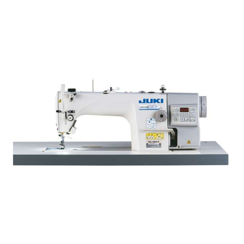
JUKI DDL-5550-6 User manual

-'l
BEFo.:n'f.'.O,FE:F.
IO'N," i'.
1. Never
operatethemachineunlessitsoil pan
hasbeen
filledwithoil.
2. After settingup the machine,
checkthe directionof
motor rotation. To check it, turn the handwheelby
handto bring
the needledown,andturn the power
switch
ON while
observingthe
handwheel.
(The
hand-
wheelshouldturn counterclockwise
asobserved
from
thehandwheel
side.)
3. Run thesewingmachine
at aspeedof 4,000s.p,m.
or
lessfor thefirstonemonth.
4. Confirmthatthe
voltage
and
phase
(single-
or3-phase)
arecorrect
by checkingthemagainsttheratingsshown
onthemotornameplate,
No.OO
-
19510304
Congratulations
on your purchase
of a JUKI
sewing
machine.
Please
readthis Instruction Manualcarefully
before
using
the unit in order to get the mostout of it
andto enjoyusingit for alongtime.
OPERATION
PRECAUTIONS
1. Keep your hands away from the needle
when you turn the
power switch ON or while the machine isoperating.
2. Do not put your fingersinto the thread
take-upcover
whilethe
machine isoperating.
3. Be sure to turn'the power switch OFF before tilting the
machineheador removing the V belt.
4. When an operator leaves
from the machine, make sureto turn
off the power.
5. During operation, be careful not to allow your or any other
person's heador hands
to come eloseto the handwheel, V belt,
bobbin winder or motor. Also,do not place
anythingcloseto
them. Doingsomay bedangerous.
6. lf your machine
is provided
with a belt cover,fingerguard
or
any other protectors, do not operate your machinewith any of
them removed.
1. INSTALLATION
-\=-_\_
-6 @4 or--=-€\r>_=,,t>
<!l
i+], O
1. Installing
the oil pan
1
) The oi1 pan should rest on the four cornersof the
machine
table
eroove.
2) Fix two rubbe-rseats
O onside @ (operator's
sidet
usingnails I asillustratedabove. Fix two cushion
seats
G) on side
@ (hinged
side)
using
arubber-based
adhesive.
Then
place
oilpan @ on thefixedseats.
oo
Fit hinge Q into theopening
in themachine
bed,and
fit the machine
headto tablerubberhinge @ before
placing
the machine
headon cushions
@ on the four
corners,

1.Information
onlubrication
l) Fill oil pan O with JUKI New Defrix Oil No. I up to
HIGH mark @
2) Whenthe oil levellowersbelow LOWmark @ , refill
theoil pan
with thesoecifiedoil.
3) Whenyou operatethe machineafter lubrication,you
will seesplashing
oil through oil sightwindow @ if
thelubricationis
adeouate.
4) Note that the amount of the splashing
oil isunrelated
to the
amount
ofthelubricatins
oil.
(Precaution)
When
you first operate
your machine
after
setupor afteran extended
period
of disuse,
run your machine
at 3,000s.p.m.
to 3,500
s.p.m.
for about10 minutes
for thepurpose
ofbreak-in.
2. Adjusting the amount of oil supplied to the face
plateparts
1) Adjusttheamountof oil suppliedto thethreadtake-up
andneedlebarcrank @ b1.'turning
adjust
pin O .
2) The minimum amount
;f oil is reached
when
marker
dot O is broughtcl6sero needle
bar crank @ by
turningtheadjust
pin
in direction
@
3) The maximumamountof oil is reachedwhenmarker
dot O isbrought
to the position
just opposite
from
the needle
bar crank by turning the adjustpin in
direction @
3.
Adjusting
the
amountofoilsuppliedto the
hook
1) More oil is suppliedas oil amount adjust screw @
mountedon thehook drivinsshaftisturnedtoward rQ
indirection @
2) As the oil amount adjustscrew @ is turned toward
Q in direction @ , theamount
of oil suppliedwill be
decreased.
3. ATTACHING
T}IE,
NEEDLE o Turn the motor power OFF before startingto
attachthe needle.
A needleof DB x I (DA x I forDDL-5550A-6)should
be
used.Selectaproper
needle
size
according
to thecount
of
threadand
thetypeofmaterial
used.
1) Turn the handwheeluntil the needlebar reaches
the
hiqhest
point
ofits
stroke.
2) Lo*osen
screw O, andhold needle
O with its
indented
part O facingexactlyto the right in
direction (El
Insert the-needlein the direction of the arrow until
it will go
no further.
Securely
tightenscrew €) .
_
Check thai long groove O of the needle
is facing
exactlyto the
left in direction @
3)
4)
s)
4. SETTINGTHE
BOBBIN
INTOTHE
BOBBIN
CASE
Hold the bobbin in a wav that the thread
openendis
directedto the right asobserved
from you, andsetthe
bobbiitinto thebobbincase.
Pass
the thread through threadslit 6 , and pull the
thread
in direction @ . By so doing,the threadwill
pass
underthe tensionspring
andcomeout from notch
o.
Checkthat the bobbinrotatesin the direction
of the
arrow
whenthread @ is
pulled.
l)
L)
l)
"(
'3oK,

s. THREADIN:Gl:ll.rfpg,l'MAC]H,l'xe,
n,EAb
\-o
i--.'-''-.-
II
,,\.
I
)l
Turn stitch length dial O in the direction of the
arrow,
andalign
the desirednumberto marker
dot @
onthemachinearm.
The
dialcalibrationisin millimeters.
When
you want to decreasethestitchlength,
turnstitch
length dial O while pressing
feed lever @ in the
directionof thearrow.
1)
2)
3)
Assemble
the threadstandunit, andinsertit in thehole
in themachinetable.
Tighten
locknut O to fix thethreadstand.
For ceiling wiring, pass
the power cord throughspool
rest
rod @
l)
2)
3)

8. INSTALLING
THEBELTCOVER
AND THEBOBBIN
1.Installing
Procedure
1) Drill
twowoodenscre',r'suideholes
6 and@ inthe
machinetable.
2) Insertsupporr
O inthe
tapped
holeinthe
arm.
3) Fix belt covercollars
O and @ usingthebeltcover
setscre$,s
@ forpreliminary
installation.
4) Accuratellposition
belt coverB O , thenfix it on
collar
@
5) Fir
beltcoverA @ on
collar
@
6) Securelr.
tlx belt
cover
B O and
beltcoverA @ on
thc-
supportusing
thebeltcover
setscrews
@
D Fir bobbin
winder O at 6 and @ usins
the
rrooden
screws
@
9. ADJUSTING
THEHEIGHT
OF
THEKNEELIFTER
1)
2)
The standardheight of the presser
foot lifted usingthe
kneelifteris10mm.
You canadjustthepresser
foot lift up to.13 mm using
kneelifter adjust
screw Q . (Themax.lift shouldbe
9 mm for the
A type.)
Whenyou have adjusted
the presser
foot lift to over
l0 mm, be surethat the bottom end of needlebar O
initslowest
position
doesnot
hit presser
foot @
3)
I
I
1O.
PEDAL
OPERATION
1. The pedal isoperated in the following four steps:
1) Themachinerunsat low sewingspeedwhen
you lightly
depress
thefront partof the
pedal. @
2) Themachinerunsathighsewingspeed
when
you further
' depress
thefront part oT
theped'al.
O (If theautomatic
reverse
feed
stitching
hasbeen
preset,
the machine
runs
at high speedafter it completes
reversefeedstitching.)
3) The machine
stops
(with its needieup or down) when
youresetthe
pedai
to its
original
position. @
1) The machinetrims threadswhen you fully depress
the
back
part
of the
pedal. e
* If your machine
isprovided
with the
Auto-lifter
iAK-3
1),
anaddition
step
is given
between
themachine
stopan,J
threadtrimmins
step.
The presser
foot gbes
up when
you lightly depress
the
back
partof the
pedai0 ,and
if youiurther
depress
the
back
part,
thethread
trimmer
isactuated.
r If you resetthe pedal
to its neutral
position
during
the
automatic reverse
feed stitching at seam start. the
machine
stopsafter
it completes
thereverse
t'eedstitching.
e Themachinewill perform
normal
thread
tnmmingeven
if
you depress
the back part of the pedalimmediately
followinghighor1owspeedsewing.
,t
r The machinewill completelyperform thread trimming
even if you resetthe pedal to its neutral position
immediatelyafter the machinestartedthread trimming
action.
. When
themachinestopswith itsneedledown.
and
if you
want to bringthe needleup. depressthe backpart of
the
pedal
once.

1. Adjusting the needlethread tension
1) As
you turn thread
tension
No. I nut O clockwise
(in
' direction @ ). the threadremaining
ontheneedle
after
threadtrimming
willbeshorter.
2) As you turn nut O counterclockwise
(in direction
@ 1.
thethread
lengthwill
be
longer.
3) As
vou turn thread
tension
No. I nut O clockwise
(in
' direction O ). the needle thread tension rvill be
increased.
4) As you turn nut O counterclockwise
(in direction
O ), theneedle
threadtensionwillbe
decreased.
2. Adjusting the bobbin thread tension
1) As you tr:f tension adjust screw @ clockwise
(in
direction € t. the bobbin thread tensionwill be
increased.
2) As you turn screw@ counterclockwise
(in direction
O ),the
bobbinthread
tensionwillbedecreased.
.''.l...?i;,,'
1.Changing
thestroke
of threadtake-up
springO
l) Loosensetscrew
(O
2) As you turn tensionpost O clockwise
(in direction
6 ), t!. stroke of the threadtake-up
spring
will be
lncreaseo.
3) As you turn the knob counterclockwise
(in direction
@ ), the
strokewillbedecreased.
2.Changingthe
pressure
ofthread
take-up
spring
O
1) Loosensetscrew
O ,andremove
tension
post @ '
2) Loosen
setscrew
@
3) As you turn tensionpost @ clockwise
(in direction
@ ), the
pressure
willbe
increased.
4) As you turn the post counterclockwise
(in direction
@ ), thepressure
will bedecreased.
l)
2)
r)
4)
To stopthe machinewith its presser
foot up, turnhand
lifter Q in direction @
The
presser
foot will go
up about5.5mm andstop.
The presser
foot will go back to its original
position
when
handlifter isturneddownin direction @ .
Usingthe kneelifter, you can get the standard
presser
foot lift of about10
mm and
themaximumlift of about
13
mm.
14. PRESSER
TFOOT
PRE$,$URE
.'
'' :
i.
Loosennut @ . Asyou turn presser
springregulator
O
clockwise
(in direction @ ), the presser
foot pressure
will be
increased.
As you turn the presserspring regulator counter-
clockwise (in direction @ ), the pressure
will be
decreased.
After adjustment,tighten
nut €)
1)
2)
3)
4) For general
fabrics,the standardheight
springregulator
is 29 to 32 mm (5kg,1
DDL.sss0H-6).
of the presser
(7kg for the

-1
l S. ADJUSTING
THEFEED
TI'MIIHG
l) To obtainthe standard
feedtiming.alignsetscrew
@
on feedeccentriccam O with setscrew
@ onmain
shaft
thrustcollar @
Tomakeadjustment,
loosentrvosetscrews
@ torelease
the feedeccentriccam,
properll,'
position
theeccentric
cam.Thenretishtenthesetscrews.
To advancethe feedtimins
in orderto Drevent
uneven
materialfeed, move the Jeed e.cetrtric
cam in the
directionofthearrow.
To delay the feed timing in order to increase
stitch
tightness,move
the feedeccentriccanr
in theopposite
direction
fromthe
arrow.
Be carefulnot to move
thefeed
orelseneedle
breakaee
mavresult
?)
4)
s) eccentric
cam too far,
I
(Standard
feed
timing)
||
Needle
:zzrww\oNzzzz 16s631
Feed
dog ' plate
16. TILT
OF
THEFEED
DOG
Thestandard
tilt (horlzontal)
of the
leeddog
is
obtained
when marker dot 6 on the feedbar shaftis aligned
withmarker
dot @ onfeed
rocker O
To tilt thefeed
dog
withitsfront
upinordertoprevent
puckering,
loosen
the setscrew,andturn the feed
bar
shaft90 degrees
in the direction
of the arrow.using
a
screwdriver.
@ Frontup @ Standard @ Frontdown @ Throat
plate
3) To tilt the feeddog with its front down in orderto
prevent
unevenmaterialfeed,turn the feedbarshaft90
degrees
in theoppositedirection
from thearrow.
(Precaution)
Whenever
the feeddog tilt is adjusted,the
feed
dogheightwill bechanged.So,it isnecessarytocheck
theheightaftertilt adjustment.
&vr.rn
^
)\
-N\-\ ,rl
"N*"\ I
--r-----v
1)
L)
17.HEIGHTO'F
THEFEEDDOG
Thefeed
dogis factory-adjustedso that it juts out from
the throat platesurface
0.8 mm to 0.9 mm (1 mm for
DDL-5550H-6).
For the DDL-5550A-6,
it juts out 0.7mm to 0.8mm.
If thefeed
dog
juts out to6much.
puckering
mayresult
when sewing light-weightmaterials. (Recommended
protrusion:
0.7mm to0.8mm)
To adjusttheheight
of thefeeddog:
@ l,oosenscrew @ ofcrank O
@ Movethefeedbarup or downto makeadjustment.
@ Securely
tightenscrew @ .
1)
2)
{l
@ Feed
dog @ Throat plate
(DDL-b5506)
0<?-0.9..
_NVVWV{\),-
o t7-
6
(DDL-5550A6) o 7-0 8"
-
_NNNNV{\}
@ tr-
{t
1
8. NEEDLE.TO-HOOKRELATIONSHIP
1.
Adjustthe timing betweenthe needleandthe
hook
as
follows:
1) Turn the handwheelto bright the needlebar down to
thelowest
pointof its
stroke,
andloosensetscrew
O .
(Adjusting
theneedle
barheight)
)) '(fot i og needle) Aligrimirker line 6 onneedlebar
O with the bottom end of needlebarlower bushing
@ ,thentightensetscrew
l)
(Fora DA needle)Align markerline @ on needle
bar
O with the bottom end of needlebar lowerbushing
0 ,thentightensetscrew
Q
(Adjustingposition @ of the
hook)
3) (For
a
DBneedle)
Loosenthe three hook setscrews,
turn the handwheel,
and align marker line @ on
ascending
needlebar O with thebottomend
ofneedle
barlower
bushing
@
(For
aDA needle)
Loosenthe three hook setscrews,
turn the handwheel,
and align marker line O on
ascending
needlebar O withthebottomend
ofneedle
bar
lower
bushing@ .
4) After makingtheadjustments
mentioned
in the above
steps,align
hook blade
point tp with the centerof
needie
@ . Provide
a clearance
of 0.04
mm to0.1
mm
between
theneedle
and
thehook, then
securelytighten
thehooksetscrews.
il ''o r i >-v-'-
. wJrn
trpraclngttrertoor.,tp..irv
its
part
rtro.irrqrssE
111092251
for DDL-5550H-61.
19. ADJUSTING
THEHEIGHT
OF
THEPRESSER
BAR
l) Loosen
setscrew
Q , andadjust
the
presser
bar
height
ortheangfeof thepresser
foot.
2) After adjustment,securelytightenthesetscrew.
I
20. COUNTER
KNIFE
T- 1. When the knife sharpnesshas deteriorated.
resharpen
counter
knife O as
iflustratedin Fig. @ .and
properly
reinstallit.
1) If the mounting
positionof the counterknife ismoved
in direction @ from thestandardmountingposition,
the thread
lengthafterthreadtrimmingwill beincreased
/-o-\
/ ra1
\4
\./
\.....--,--' L) accordingly.
If the mounting
positionismovedin direction @ , the
threadlengthwill bedecreasedaccordingly.
Movingknife
Center
of needle
Standard
:4.0 mm
,')--,-
',rL-=-{--
21. ADJUSTING
THETHREAD
TAKE.UP
STROKE
--\ |
5z'r \ )
i 't
'i]
+@ @+ 1)
2)
3)
When
sewingheavy-weight
materials,movethread
guide
0 to theGft 1indireJtion O ) to increase
thelJngth
of thread
pulled
outby thethread
take-up.
When
sewinglight-weight
materials.move
threadguide
0 to therlghilin dir6ction @ ) to decreasethelJngth
of thread
pulled
outby thethread
take-up.
Normally,threadguide Q is positioned
in a way that
marker
line @ isaligned
with thecenter
of thescrew.
22. ADJUSTING
THENEEDLE
STOP
POSITION
1.Stop
position
afterthreadtrimming
1) Thestandardneedlestop
position
is
obtainedby aligning
red marker dot O on the rnachinearm with white
markerdot @ on the
handwheel.
2) Stop
the
needlein itshighest
position,
loosenscrew Q
toperform
adiustmentwithintheslot
of thescrew.
C Theneedle
stop timingis advanced
if you movethe
screwin directibn
O -.
p The needlestop rimingis delayedii you movethe
rcrewindirectlonO
{Precaution)Do not operatethe machinewith screw l)
loosened.Justloosen
the
screw,anddo notremove
it.
1.Lower
stop
position
1) The lower needle stop position when the pedal is
returned to the neutral position after the front part
of the pedal is_depressedcan be adjustedasfollows:
Stop needle 0 li its lowestposition.
loosen
screw
Q , andmake
adjustmentwithin theslotof the
screw.
Movingthe screwin direction 6 advances
theneedle
stoptiming. Moving
thescrewin direction @ delays
the
tlming.
{Precaution)Do not operatethe machine
with screw Q)
loosened,
Justloosen
thescrew,anddonotremoveit.

1.
Adjusting
the pressure
requiredto depressthe
front part
of thepedal
1) This pressure
canbe changed
by alteringthe mounting
position
ofpedaling
pressure
adjustspring O .
2) Thepressure
decreases
when
you hook thespringonthe
left side.
3) Thepressure
increases
whenyou hook thespringonthe
rishtside.
Adjustingthe pressure
requiredto depress
the
back
partof thePedal
This
pressure
can
beadjustedusingregulator
screw O
The
pressure
increasesas
you turn theregulator
screwin.
The
pressure
decreasesas
you turn thescrew
out,
Adjustingthepedal
stroke
The pedal
strokedecreases
whenyou insertconnecting
rod O into theleft hole.
2.
l)
2)
3)
3.
1)
1.Installing
theconnectingrod
1) Move pedal O to the right or left asillustratedby
the arrows so that motor control lever O and
connecting
rod €) arestraightened.
2.Adjustingthe
pedal
angle
l) The pedal tilt canbe freely adjustedby changing
the
length
of theconnectingrod.
2) Loosen adjust screw @ , and adjust the length of
connectingrod O .
REVERSEFEED
STITCHING
MECHANISM
1.
How
to operate
1) The moment switch iever (O is pressed,
the machine
performs
reversefeed
stitching,
2) The machine
performs
reversefeedstitchingas
longas
theswitchleverishelddepressed.
3) Themachineresumes
normalfeedstitchingthemoment
theswitchleverisreleased.
2.Height
of the
switchlever
1) Adjust the height of switchlever O sothat it canbe
easilvooerated.
2) Loosen'screw O , and move the switch lever up or
downto adjustitsheight.
-8--

1.Positioning
thewiper
Adjust the position of the wiper according to the
thickness
of thematerial
sewn.The
adjustment
procedure
is
asfollows:
1) Turn thehandwheel
in thenormaldirection
of rotation
to alignwhite marker dot l) on the handwheel
with
red
marker
dot O on themachine
arm.
2) Adjust the distance
betweenthe flat part of the
wiper
andthecenter
of theneedleto 1mm.
Tighten wiper adjust screw 0 so that the wiper
is
pressed
andfixedby wiper
collar @
3) Whenthe wiper is unnecessary,
turn wiper switch @
OFF.
l
I
I
I
I
i
(
n--..'.----------..a\
27. SPECIFICATIONS
DDL-5550-6 DDL5550A-6 DDL-5550H-6
Application General
fabrics,light-weight
materialsandmedium-
weight
materials
General
fabricsandlight-
weightmaterials Medium-weight
materials
and
heavy-weight
materials
rylq:r'g__ l
i!9!:sl
y.db _
Presseriootlift r
_l!jry_:Ill1l ____
l-Lrbricating
orl -l
Yt I'mo:r:* | __Yglol$':_
Max.4
mm
___?l-x1#r-tl8 DAxr
#e-#11
l0 mmt.standarelj
____1_llry11.] ___i _lr* (i1i:l _l
Jukirl"ew
Defri,xOil No. I
__i5I9q!{
Max.5mm
DBxl #19-#23
l0 mnr
(standard)
l3 mm
(max.)

28. AUTO-LTFTER
(AK-3O
ORAK-311
(AVATLABLE
ON SPECTALORDERI
* TheAK-30or AK-31isdesigned
to automatically
raisethepresser
foot for 60seconds
after
completion
of threadtrimming.
TheAK-30 or AK-31usesanexclusive
motor.
1.How
to usetheAK-30
1) Whenit is necessary
to raise
sewing,stopsewing
anddepress
2) The moment you releasethe
foot comesdown.
2.How
to usetheAK-31
1) Referto"10.PEDAL
OPERATION"
3.AdjustingtheAuto-lifterstroke
1) Ioosen
locknut O .
2) Loosenlocknut @ of stopper
(A) O ,andfully lower
thestopper
(A).
3) Actuate the solenoid
under the condition described
in
step 2) above,and check if the presser
foot islifted
about
l0 mm.
If the presser
foot lift exceeds
l0 mm, turn plunger @
counterclockwise
to adiust the lift to 10 mm. If the
presser
foot lift is less-thanl0 mm, turntheplunger
clockwiseto adjustthelift to 10mm.
4) Actuate
the solenoidto cause
stopper
(A) O to come
into contactwith theoil reservoir.
5) Tum the kneeswitch OFF, then raise
stopper(A) O
anadditionalturn.
6) Tightenlocknutofstopper(A) O andlocknut Q
7) Raisestopper
(B) O until it comesinto contact
with
the oil reservoir,then
provide
aclearance
of aboutI mm
between
the indented
part of lifter lever () andknee
lifter pushing
rod O comingfrom theoil reservoir.
8) Tightenlocknut
@ ofstopper(B) @
the presserfoot while
kneeswitch O
knee
switch.thepresser
o
o!-.o
(@)
d\:-/@
:
t-----------r
/l
a E tr= E- .E El
ggtrEtr
. Operation
Precautions
1) WhenusingtheAuto-lifter,AK-30orAK-31,
that No. t-(ff.ON) of DIP iwitch O mounted
PSC
circuitboard
hasbeen
setto ON.
2) If you wantto hold thepresser
foot in itsupper
position
after thread
trimmingfor an unlimitedtime rather
than
just 60 seconds,
setboth No. 1 (FLON) and No. 2
(FLPW)
to ON.
By sodoing,
you cankeepthe presser
foot in its upper
position for an unlimited time after threadtrimming.
Flowever,if you leave
your machinefor an extended
time,rememberto turn thepower
switch
OFF.
be
sure
onthe
3)
-10-

SWITCHES
INTHE
PSCBOX
Mzloot
30| IREV
n RIKP-4sv-o
r-\
TP6
s 6tD
r-)
TP5
sNUU-0
ilt t248
t" 9rl
loX\*l
r, l-\}1.l
IPl I ss! I
+tav , .
sw2, ,
Lh
bEl
BrsuB
FD^l
JraxI El,l
lro
| -l
ON/OFF
of the
selectorswitches
[_-_l
l;lu- |
I-TI I
| | ]rol
t-l
l--
t=
ll
I
<- SwitchOFF
+ SwitchON
1. SetDlPswitches
O , O and O mounted
onthepSC
circuitboard
to ON
or OFFasnecessary.
l) When
using
the Auto-lifter
(AK-30 5r AK-31),
besure
thatNo. I (FLON) of DIPswitch Q has
beensetto
oN.
Besureto setNo.
2(FLPW)
andNo.3 (FLNS)
to OFF.
If you want to keepthe presser
foot up after tluead
trimming for an unlimited time rather than lust 50
seconds,setNo. 1
(FLON)
andNo.2 (FLPW)
to0N.
(Be
sure
tosetNo.
3
(FLNS)
toOFF.)
When you need the soti start tbnction,set No. 7
iSOFTON)
of DIP
switch lO to ON.
Switch
No. 8 (SOFT1/2)
is usedto selectl-stitch
or
l-stitchsoftstart.When
yousetthisswitchroOFF,the
machinewill perfurml-strtch
softstart. When
you set
it toON,thernachine
wiliperform
2-stitchsott
srarr,
The soft start speedis normally set to 800s.p.m.,
however, it can be adjusted using variable resistor
(SOFT) @ . Turningit clockwise
( .V ) increasesthe
soft startspeed,
andturning
it counterclockwise
( f. )
decreasesthespeed.
(Decrease
thesoft startspeed
if the needlethreadtends
to fail to interlacewith the bobbin threadat sewing
start.)
DIP switches 0 and () ate used for reversefeed
stitching. Thesettingsof theseswitchesdependon the
machinemodel. Checkthe settingsagainst
the table
2)
3)
6)
,+)
( DIP
switch0 )
Switchname
I ON/OFF
HOSAO I OFF
HosA
i I orn
HOSB
0 | Opp
HOSBi i ON
( DIP
switch
@ )
Switch
name ON/OFF
ACTA OFF
ACTB ON
ACTD ON
HOSD
OOFF
HOSD
ION
: E r---.rE =,6;. f \ j'BI
lgE trtrE f-1.' t----'' s
,/ sw3
' FDISAl^r
EDISB
REVOT
SAST€
TESTA
T€ST8
TESTP
given
Lelow:

rJl.lKl
JUKICORPORATION
HEAD
OFFICE
2-1.8-CHON/E,KOKURYO.CHO
CHOFU-CITY,
TOKYO,JAPAN
EUSINESS
OFFICE
233 KABUKI-CHO
]-CHOME
SHINJUKU-KU.TOKYO160.JAPAN
CABLE:JUKI
TOKYO
TELEX
: J22967,232-2301
PHONE:
03(205)1188,1183,1190
Please
do not
hesitateto contaclourdrstributorsor
necessary
XAppearandspecificationlrsledin
this
instruction
agentsin
your
area
for furtherIniormationswhen
marualaresLbJecteo1o
change
wrthorrl
'lotice
19884 Printedin Japan
Table of contents
Other JUKI Sewing Machine manuals

JUKI
JUKI HZL-DX3 User manual

JUKI
JUKI LK-1900BN User manual

JUKI
JUKI PS800-8045 User manual

JUKI
JUKI MO-104N User manual

JUKI
JUKI MF-7200D User manual

JUKI
JUKI HZL-G Series User manual

JUKI
JUKI MF-7700 Series Quick start guide

JUKI
JUKI DNU-1541S User manual

JUKI
JUKI SC-921 User manual

JUKI
JUKI LH-4500C Series User manual