4SC-TSL (07-23) REV-0
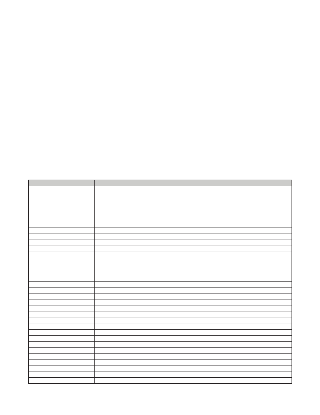
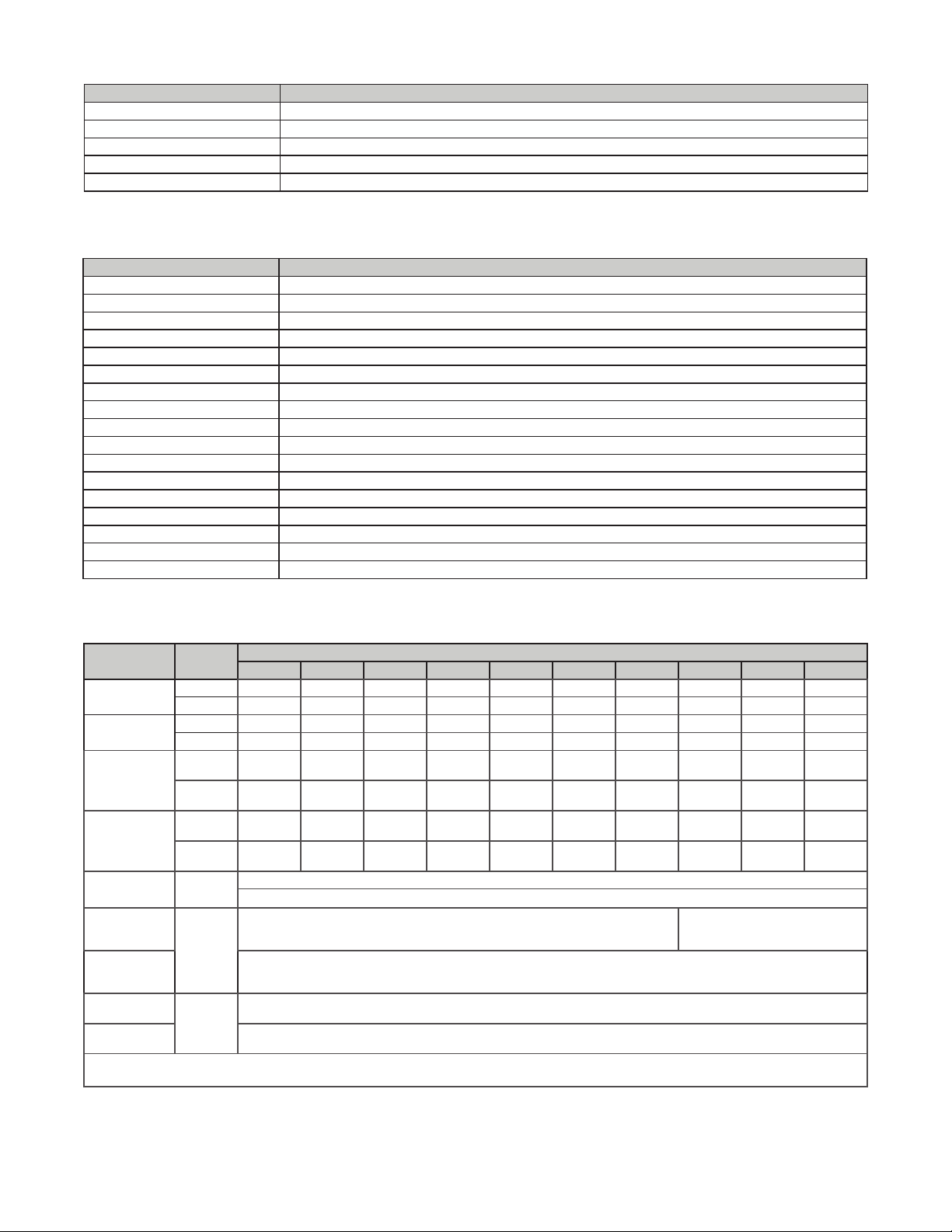
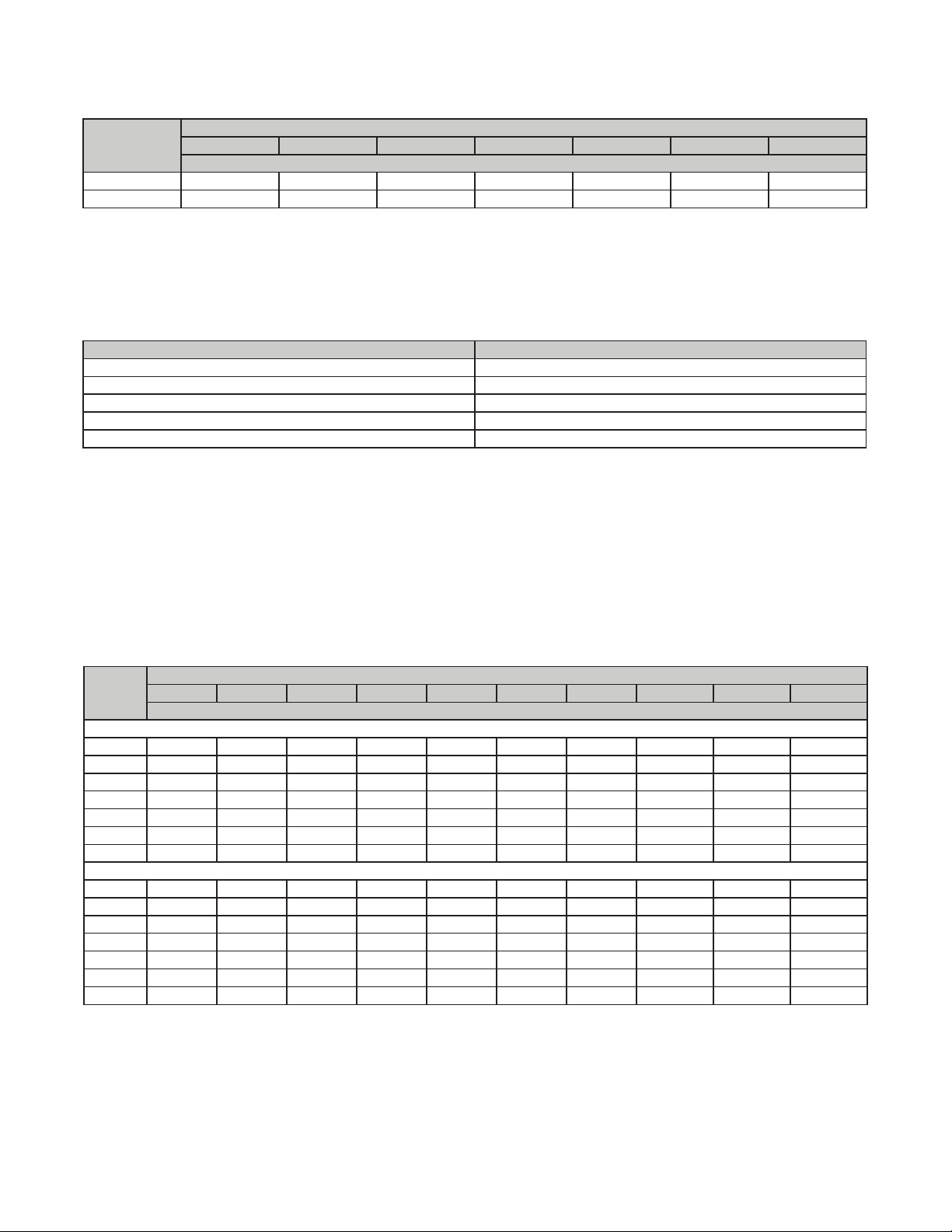
TECHNICAL SPECIFICATIONS—CONTINUED
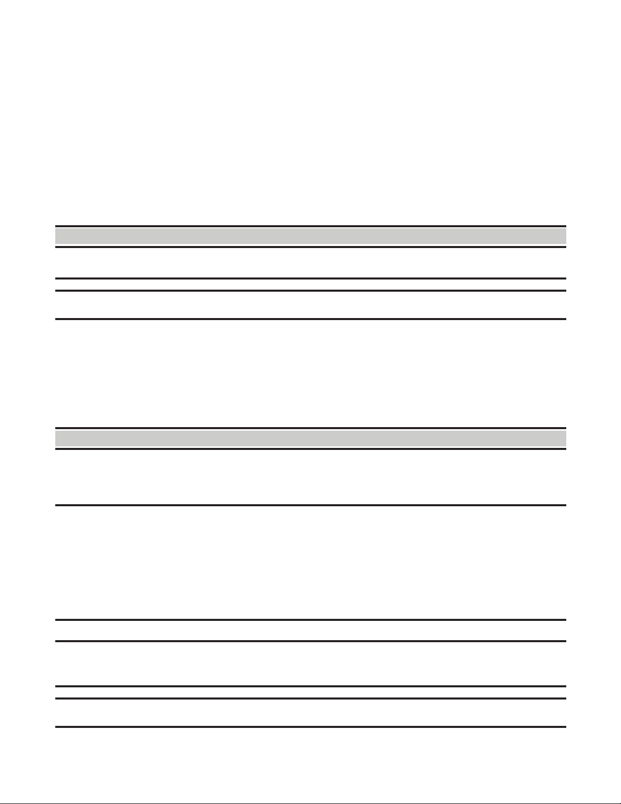
Certification
These gas-fired products are certified by ANSI Z83 family of standards governing the safe usage of heating equipment
in the industrial/commercial marketplace. This includes using the heaters in makeup air applications to supply corridor
pressurization in commercial buildings such as office structures and apartment complexes. The heaters are not
certified as residential heating equipment and should not be used as such.
Installation Codes
• These units must be installed in accordance with local building codes. In the absence of local codes, in the United
States, the unit must be installed in accordance with the National Fuel Gas Code NFPA/ANSI Z223.1 (latest edition).
A Canadian installation must be in accordance with the CSA B149.1 Natural Gas and Propane Installation Code.
This code is available from CSA Information Services, 1-800-463-6727. Local authorities having jurisdiction should
be consulted before installation is made to verify local codes and installation procedure requirements.
• Clearances from the heater and vent to combustible construction or material in storage must conform with the
National Fuel Gas Code ANSI Z223.1 (latest edition) pertaining to gas-burning devices, and such material must
not attain a temperature over 160°F (71°C) by continued operation of the heater.
• Special installations (aircraft hangars/garages): Installations in aircraft hangars should be in accordance with
NFPA No. 409 (latest edition), Standard for Aircraft Hangars, in public garages in accordance with NFPA No. 88A
(latest edition), Standard for Parking Structures, and for repair garages in accordance with NFPA No. 88B (latest
edition), Standard for Repair Garages. In Canada, installations in aircraft hangars, repair garages, and parking
garages should be in accordance with the requirements of the enforcing authorities and in accordance with CSA
B149 codes.
Unit Location
⚠ CAUTION ⚠
Do not locate the unit where it may be exposed to liquid spray, rain, or dripping water.
• A duct furnace is designed for connection to an inlet and an outlet duct and depends on an external air handler.
The location must comply with the Clearances section. There are a variety of factors, such as system application,
building structure, dimensions, and weight, that contribute to selecting the location. Read the installation manual
and select a location that complies with the requirements.
• For best results, the heater should be placed with certain rules in mind. In general, a unit should be located from
8–12 feet (2.6–3.6 meters) above the floor. Units should always be arranged to blow toward or along exposed wall
surfaces, if possible. Where two or more units are installed in the same room, a general scheme of air circulation
should be maintained.
• Suspended heaters are most effective when located as close to the working zone as possible, and this fact should
be kept in mind when determining the mounting heights to be used. However, avoid directing the discharged air
directly on the room occupants.
• Partitions, columns, counters, or other obstructions should be taken into consideration when locating the unit heater,
so that a minimum quantity of airflow will be deflected by such obstacles. When units are located in the center of the
space to be heated, the air should be discharged toward the exposed walls. In large areas, units should be located
to discharge air along exposed walls with extra units provided to discharge air in toward the center of the area.
• At those points where infiltration of cold air is excessive, such as at entrance doors and shipping doors, it is
desirable to locate the unit so that it will discharge directly toward the source of cold air from a distance of 15–20
feet (4.5–6 meters).