RF-System TinyGate Use and care manual

TinyGate
USB Digimode Interface
Instructions for Assembly
and user's manual
(Last change: 19/07/2017

TinyGate - User's manual and assembly instructions
Copyright
The contents of this document (of a merely exemplary function and thus non-exhaustive: docu-
ments, texts, images, audio and video data, logos, brands, all hereafter referred to as "Con-
tents") are the exclusive property of the R -SYSTEM and thus protected by the current legisla-
tion regarding copyright protection.
All rights reserved.
The reproduction and / or diffusion, even partial, by some analog and/or digital means, without
the written consent of the copyright holder is forbidden. As a result, any unauthorised use of
the "content" below is the full and exclusive responsibility of the users who respond them-
selves, according to the laws and regulations in force. The electronic copy of this manual is ex-
clusively authorised for personal and study use, without any commercial aim, on written re-
quest. The aforementioned R -SYSTEM reserves the right to make modifications and/or im-
provements to the assembly box at any time, without updating this manual
Copyright 2016 RF-SYSTEM ©
http://www.rfsystem.it
P a g e 2

TinyGate - User's manual and assembly instructions
Table of contents
Introduction ................................................................................................................................................. 5
Warnings ...................................................................................................................................................... 6
Disclaimer ................................................................................................................................................ 6
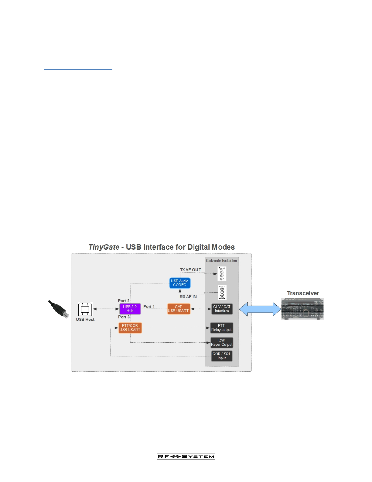
Technical characteristics .............................................................................................................................. 8
Technical specifications ............................................................................................................................. 10
Before beginning ....................................................................................................................................... 12
Soldering advice ........................................................................................................................................ 13
Preparation and setup ................................................................................................................................. 14
Assembly ................................................................................................................................................... 15
Circuit board .......................................................................................................................................... 15
Enclosure kit - Box ................................................................................................................................ 21
Connection cable for the transceiver ...................................................................................................... 23
The transceiver cable ............................................................................................................................. 26
Examples of connection with transceivers ............................................................................................. 28
Icom IC275, IC725, IC726, IC728, IC729, IC735, IC736, IC737, IC738, IC746PRO, IC756PROIII,
IC761, IC765, IC775, IC781, IC820, IC821, IC910, IC970, IC7400, IC7600, IC7700, IC7800 ........ 29
Yaesu FT100D, FT817, FT857, FT897 .............................................................................................. 31
Yaesu FT1000 MARK-V, FT1000, FT990 ......................................................................................... 33
Yaesu FT840 ...................................................................................................................................... 35
Yaesu FT2000, FT920 ........................................................................................................................ 37
Yaesu FT450, FT950, FT991 ............................................................................................................. 38
Icom IC2720H, IC2725E ................................................................................................................... 38
Kenwood TS480, TM255, TM455, TM-G707, TM-V7, TM-D700x ................................................. 38
Kenwood TS140, TS440(S , TS450S, TS570, TS590, TS680, TS690, TS850, TS870S, TS940(S ,
TS950S, TS990, TS2000(X .............................................................................................................. 39
Kenwood R1000 ................................................................................................................................ 40
Kenwood TS50S ................................................................................................................................ 41
Icom IC703, IC706, IC718, IC7000, IC7100, IC7200, IC7300, IC7410, IC9100 .............................. 42
CAT / CI-V interface .................................................................................................................................. 43
CAT/CI-V connections ........................................................................................................................... 43
CAT for ELECRAFT-Transceivers ........................................................................................................ 46
P a g e 3

TinyGate - User's manual and assembly instructions
CAT / CI-V power supply ...................................................................................................................... 47
PTT / CW / FSK outputs ............................................................................................................................ 49
SQL (COR Input ...................................................................................................................................... 52
Test – Initial operation ............................................................................................................................... 55
Windows XP .......................................................................................................................................... 56
Windows 7 ............................................................................................................................................. 59
Windows 10 ........................................................................................................................................... 61
Linux - Ubuntu ...................................................................................................................................... 63
MacOS -X .............................................................................................................................................. 66
Examples of configurations for digital modes applications ....................................................................... 69
Ham Radio Deluxe V 5.24- Digital Master 780 ..................................................................................... 72
WSJT-X ................................................................................................................................................. 79
FLDIGI & MacOS ................................................................................................................................. 80
P a g e 4

TinyGate - User's manual and assembly instructions
Introduction
The TinyGate Interface was created by Martin, IW3AUT and it’s a compact
USB interface for transceivers, which a ows operation in digita modes via PC
such as for examp e: PSK31, RTTY, WSPR, SSTV, EchoLink, APRS, Pactor, ROS as
we as many others.
As a 3-in-1 interface it makes available via a USB port a sound card interface, a
C T / CI-V interface and a PTT / SQL / CW / FSK with a galvanic isolation
between the transceiver and the PC with transformers and optocouplers. The
TinyGate Interface can be used with a wide variety of software applications for
digital modes, which are available as freeware, shareware or as commercial
products. As a resu t, this provides the amateur radio operator with easy and
manageab e access to the wor d of digita modes, thanks to the wide f exibi ity
of adaptation of this interface to a most any transceiver.
P a g e 5

TinyGate - User's manual and assembly instructions
Warnings
Disclaimer
This assemb y box is made exc usive y for radioamateur and educationa -ex-
perimenta use. As a resu t, it shou d be assemb ed and used by an expert with
experience in the assemb y of e ectronic circuits.
We do not accept any responsibi ity for bodi y or materia damage caused by
the construction and use of this assemb y box. As a resu t, assemb e and use
this kit at your own risk.
The operation may not be guaranteed, and even ess so its e igibi ity for use of
certain app ications. The user shou d verify its app icabi ity for their own ap-
p ications and is responsib e for the atter.
Errors of access and use are factors that are beyond our contro , we are there-
fore not responsib e for bodi y or materia harm caused by these errors or in-
experience.
The guarantee app ies exc usive y to the individua parts (on the condition that
these are assemb ed correct y) and not to the assemb ed product. The afore-
mentioned RF-SYSTEM reserves the right to make modifications and/or im-
provements to the assemb y box at any time, without updating this manua .
The two kits, once assemb ed, may not be reso d if the necessary ega author-
isations have not been previous y requested and obtained.
Before using with a transceiver or receiver, the bridges on
the JP1 socket must be configured correct y.
Incorrect configuration of these bridges may cause damage
to the TinyGate and/or to the connected transceiver or re-
ceiver.
· It is advised that the parts are kept out of reach of chi dren and away from
pets, as they are a choking hazard.
· Do not inha e the fumes from the we ding. Use a fi ter or device to remove
these from the work station.
· Aerate the room after the we ding activity.
P a g e 6

TinyGate - User's manual and assembly instructions
· When using a so dering iron, p ace it down on y once the rod has coo ed
down proper y.
· Do not so der on ive circuits.
· Carefu y fo ow the instructions provided in this manua .
· In case of any doubt concerning the procedures to be fo owed, seek technica
assistance.
· Do not try to modify the parts of the circuit that have a ready been as-
semb ed.
P a g e 7

TinyGate - User's manual and assembly instructions
Technical characteristics
•3-in-1 USB interface, just only one USB cable to your PC: built-in USB
2.0 Hi h speed Hub
•Full galvanic isolation between radio and USB interface
•Integrated USB sound device:
The power supp y from the USB host is fi tered additiona y to keep a ow
noise on the A/D and D/A converters
Supported by the fo owing operating systems: Windows XP, Windows 7,
Windows 8, Windows 10, Macintosh OS X and LINUX.
Comp iant with USB Audio Device C ass Specification v1.0, there are no
custom device drivers necessary.
•Provides 2 independant integrated USB COM-Ports:
1) CAT/CI-V serial interface:
Support for fo owing radio contro ports: CI-V, FIF-232, IF-232
(RXD+TXD)
Supported by the fo owing operating systems: Windows XP, Windows 7,
Windows 8, Windows 10, Macintosh OS X and LINUX.
2) TT/SQL/CW/FSK interface:
Sque ch(COR) input, positive or negative ogic (for Echo ink and remote
contro app ications)
PTT re ay output: direct keying contro without VOX circuit
CW/FSK so id state output (can a so be used as PTT: The smart jumper
system a ow to use either a re ay or a so id state output as PTT)
Supported by the fo owing operating systems: Windows XP, Windows 7,
Windows 8, Windows 10, Macintosh OS X and LINUX.
•Contro s for receiver and transmitter audio eve
•Quick change USB and Radio interface connectors
•RJ45 connector for transceiver connection with a f exib e pin se ection
jumper socket (attached to MIC connector, accessory or data port works
with virtua y a transceiver). A detachab e radio cab e can be made eas-
i y with a standard unterminated RJ45-FTP network patch cab e (get a
P a g e 8

TinyGate - User's manual and assembly instructions
patch cab e and cut/remove one of both RJ45 connectors), where you
can so der a suitab e connector for your transceiver. Here as examp e the
cab e for a ICOM IC7400 transceiver:
•Leds for USB Audio device, PTT and CAT RXD/TXD activity
•All communication software which support a standard sound card
and a serial port for the TT can work with the TinyGate. Due the in-
dependent sound interface and COM-Ports it can be used a so with any
combination of CAT, remote operation and data software ike MixW,
Hamradio De uxe, DigiPan, MixW, FLDigi, RemAud etc.
P a g e 9

TinyGate - User's manual and assembly instructions
Technical specifications
•USB 2.0 High speed interface
•USB Power requirements: 5V, max. 120mA
•Board size: 65x80mm
•USB sound interface (codec):
Chip: CMedia CM108AH
48 / 44.1kHz Samp ing Rate for Both P ayback (D/A) and Recording
(A/D)
88 dB (typica ) dynamic range
16-Bit DAC Output and 16-Bit ADC Input with a 22dB Microphone Boost
Audio Output:
Leve 3Vpp max. @1kΩ typica (AC-coup ed)
Frequency response (1 dB bandwidth): 0,02 – 11,5 kHz typica (D/A fre-
quency response conditions: measured with a E-MU0202, inc ude iso a-
tion transformer)
Second harmonic: -70 dB typica
Tota harmonic distortion (THD): 0.06% typica
D/A Samp ing rates: 44.1, 48 kS/s
Audio Input:
Input impedance: 600Ω, (AC-coup ed)
max. input eve : 3Vpp, (Microphone Boost=OFF)
max. input eve : 220mVpp, (Microphone Boost=ON)
Frequency response (1 dB bandwidth): 0,02 – 15 kHz typica (A/D fre-
quency response conditions: measured with a E-MU0202, inc ude iso a-
tion transformer)
Noise f oor screen capture (span: 0 to 5kHz, 48 kHz Samp ing Rate, dis-
connected input, microphone Boost=OFF)
Noise f oor screen capture (span: 0 to 5kHz, 48 kHz Samp ing Rate, dis-
connected input, microphone Boost=ON)
Dynamic Range: 88 dB typica
A/D samp ing rates: 44.1, 48 kS/s
Audio transformers crossta k attenuation: 60dB
P a g e 10

TinyGate - User's manual and assembly instructions
•USB COM-Ports:
•Chip: FTDI FT232RL
Mu ti-Standard: CAT, FIF-232 (5V TTL), IF-232 (5V TTL), Inverted (for
E ecraft, on y for TinyGate board revision B). Max. guaranteed seria
baudrate: 19200 baud
Interface power:
externa powered from the transceiver / interna powered from the USB
(interna powered works on y without ga vanic iso ation)
PTT output: reed re ay driven from RTS, max. 100V/0,5A
CW/FSK output: optoiso ated open co ector driven from DTR or TXD,
max. 50V/50mA
Sque ch input: optoiso ated ogic high or ow to activate CTS, 4-20VDC
•Radio connector (RJ45):
Avai ab e signa s: RX Audio, TX Audio (MIC), PTT, CW/FSK, COR, CAT/Lo-
gic Supp y 8-15VDC
P a g e 11

TinyGate - User's manual and assembly instructions
Before beginning
The assembly procedure of the TinyGate may be facilitated by certain small steps:
· Organise the work space for the procedure.
· Preferab y use a wooden tab e with a sheet of antistatic map p aced on top to
prevent any parts that may fa from bouncing to the ground.
· Keep the necessary too s within arm's reach.
· Use a so dering iron whose tip is in good condition. Eventua y change it as a
preventative measure.
· Use a free so der a oy for e ectronics possib y without ead.
· Preferab y use a rigorous y earthed antistatic brace et connected to through a
resistor of 1 MegaOhm.
· Rushing is bad practice! Proceed with the most ca m approach possib e!!!
P a g e 12

TinyGate - User's manual and assembly instructions
Soldering advice
For the assemb y of the kit, no particu ar y sophisticated so dering equipment
is necessary. Even with a good pen so dering too (at east 30 watts of power)
you can obtain optimum resu ts. The key point for successfu so dering is cer-
tain y the state of the tip. Damaged tips or tips which have ost the si ver sur-
face ayer shou d be rep aced. The tip, once heated, may be effective y c eaned
by me ting a sma amount of so der a oy on it and then passing it repeated y
on a damp sponge (not soaking). The operation of c eaning with the sponge
shou d be repeated regu ar y, in order to e iminate residues of f uxing and ox-
idising agents that may bui d up on it.
Preferab y use ead-free so der a oys, even if the so dering in this case wi not
have a very shiny appearance and may as a resu t be more difficu t to com-
p ete. The diameter of the a oy to be used simp y depends on habit. Taking
into account the "step" of the parts to be so dered, a so dering a oy with max-
imum diameter of 1mm shou d be entire y sufficient. Larger diameters may be
difficu t to manage, and sma er diameters may require more wire feeding dur-
ing the fusion operations. One shou d not use f uxing agents or so dering
pastes since modern so dering irons have a core that, upon me ting, carries
out the same function as the so dering paste.
So dering operations shou d be carried out in a fast and decisive manner. Cer-
tain components (such as crysta ) do not increase in size such that their ead-
ing wires must be insisted upon with the so dering iron. The same is true of
the transformers. The so dering a oy shou d never be iquefied on the tip of
the so dering iron, but on the eading wire of the part that is being so dered,
fo owing the heating of the same. After the fusion has begun it is necessary to
app y the heat for severa moments (1 or 2 seconds) so as to comp ete the fu-
sion of the deoxidising agent and to guarantee optima e ectrica contact. Do
not exaggerate the quantity of tin that is me ted on the eading wires, excesses
tin may resu t in aesthetica y awkward so dering or in short-circuits with the
adjacent feet.
Once the so dering phase is comp ete, one shou d never b ow on the so dering
a oy. The coo ing shou d take p ace s ow y by convection.
Particu ar attention shou d be paid to the airtightness of the ground p anes. In
this case the arge meta ic surface has an e evated therma capacity, and it
may therefore be difficu t (especia y if the so dering iron is not over y power-
fu ) to produce good so dering resu ts.
P a g e 13

TinyGate - User's manual and assembly instructions
A so in this case it is on y a question of time, keeping the tip on the ground
p ane for a few seconds, such as to ight y heat it and then proceed to the use
of the so dering a oy.
If an error is made, the excess tin may be removed with a deso dering braid
(make sure it does not touch your fingers too much) or with tin remover (e ec-
trica or pump). The parts shou d be removed on y when the so dering a oy
has been correct y removed and without exerting too much force in the extrac-
tion. If the component is “stuck”, remove the tin more efficient y. App ying
force with p iers or wire cutters may ead to inso ub e damage to the printed
circuit.
Preparation and setup
The pack containing the TinyGate kit has finally arrived, so, remembering what
was said in the first section, the necessity is for a space that allows us to work com-
fortably and calmly.
P a g e 14

TinyGate - User's manual and assembly instructions
Assembly
Circuit board
Once the preparations are comp ete, you may proceed with the assemb y of
the sma parts remaining to be so dered. The parts represented in the fo ow-
ing figures may be s ight y different from those present in the kit.
Once the components have been identified it is necessary to proceed to the local-
isation of their assembly position. The operation is considerably simplified by the
presence of the white silk screen printing on the printed circuit. For this one may
also make reference to the assembly scheme at the end of the table that follows.
Pay particular attention to the precise parallel alignment of the connectors and po-
tentiometers with the edge of the board.
P a g e 15

TinyGate - User's manual and assembly instructions
List of the parts to be soldered
Pos. Description Desc.
To USB connector X4
B Jack stereo 3.5mm X3
C RCA connector (insert the part comp ete y unti the 6 white
p ugs are inserted entire y in the printed circuit)
X1
D RJ45 socket with LED X2
E 16 pin jumper socket JP1
F Reed Re ays (The orientation of this component does not
matter because of the symmetrica pinout)
(SIP-1A05 or MS05-1A87-75LHR)
K1
P a g e 16

TinyGate - User's manual and assembly instructions
G Dua LED (Red/Green)
This ed b ock shou d be a igned with the edge of the printed
circuit.
DZ1
H / I Potentiometers 10kOhm with dia
knobs
R2 / R3
P a g e 17

TinyGate - User's manual and assembly instructions
P a g e 18

TinyGate - User's manual and assembly instructions
For the re ay (F) there are present overa in the printed circuit 7 ho es with
associated so dering pads. Nonethe ess, the re ay has on y four pins: this is be-
cause the board is prepared for two different re ays with different pinout
pitch. If you find in the kit a re ay type SIP-1A05, it shou d be connected in
three round holes and in one oval. For the re ays of type MEDER MS05-
1A87-75LHR are supposed to use 4 oval-shaped pads. The orientation of the
re ay is immateria because of the symmetrica pin assignment. In a of these
cases, the position and the distance between the ho es make it a most im-
possib e to connect the re ay incorrect y.
Relay pinout details:
P a g e 19

TinyGate - User's manual and assembly instructions
View of the full assembled board:
P a g e 20
Table of contents