Manual 37249A SPM-D21 - Synchronizing Unit
Page 4/92 © Woodward
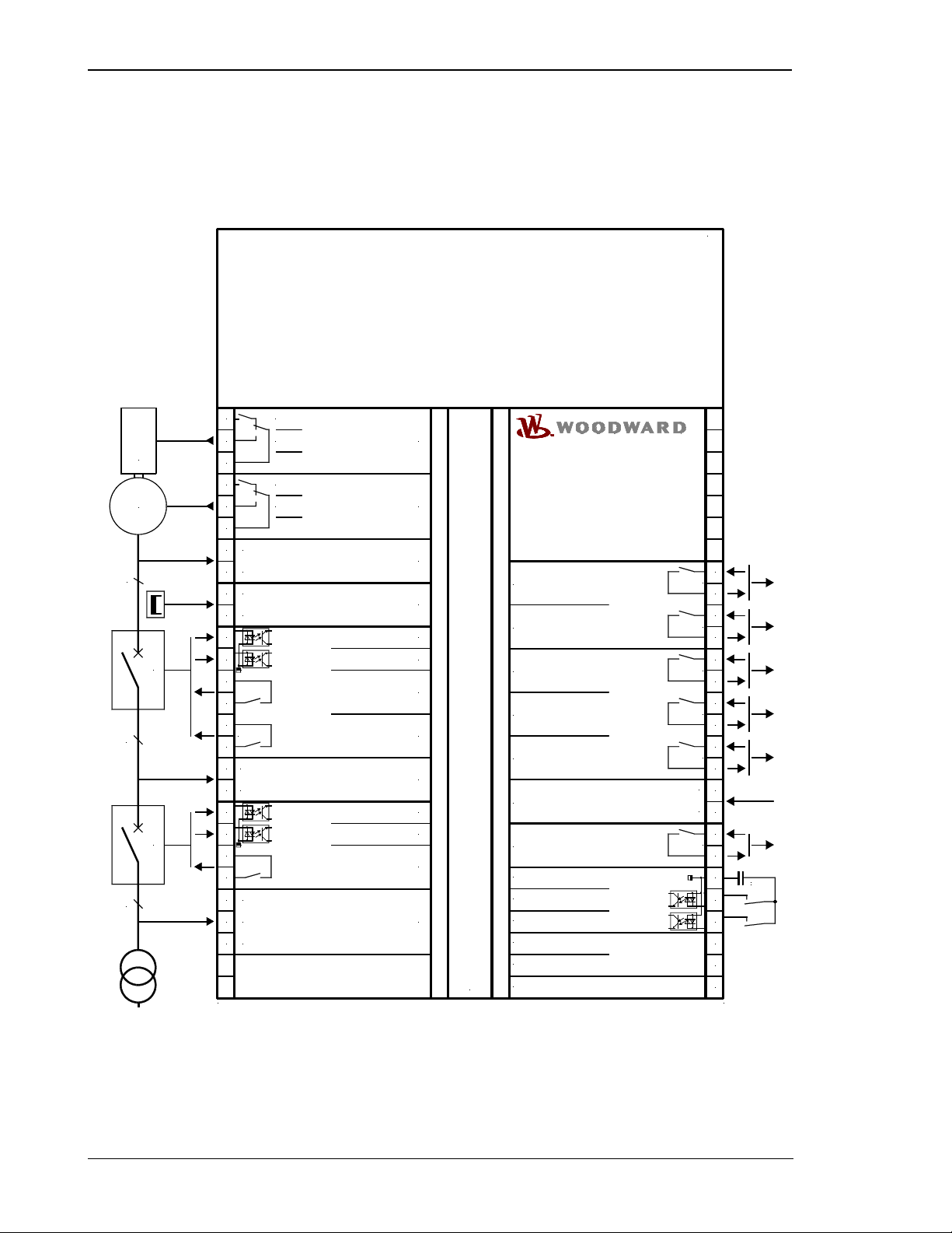
Control Outputs..................................................................................................................................... 36
Isolation Of The Power Supply From The Discrete Inputs ................................................................... 36
Analog Controller Outputs .................................................................................................................... 37
CHAPTER 5. DISPLAY AND OPERATING ELEMENTS.................................................................. 40
Brief Explanation Of The LEDs And Push-Buttons .............................................................................. 41
LEDs........................................................................................................................................... 41
Buttons ....................................................................................................................................... 41
Others......................................................................................................................................... 41
LEDs ..................................................................................................................................................... 42
Push-Buttons ........................................................................................................................................ 44
LC Display ............................................................................................................................................ 45
Display Monitoring In Automatic Mode: Double Voltage / Frequency Display........................... 45
Display Monitoring In Automatic Mode: Generator Values ........................................................ 45
Display Monitoring In Automatic Mode: Alarm Indication........................................................... 46
CHAPTER 6. CONFIGURATION ................................................................................................. 47
Configure Basic Data............................................................................................................................ 47
Password Protection .................................................................................................................. 48
Direct Configuration.................................................................................................................... 49
Configure Basic Settings ...................................................................................................................... 50
Configure Controller ............................................................................................................................. 52
Idle Control ................................................................................................................................. 52
Frequency Controller.................................................................................................................. 53
Voltage Controller....................................................................................................................... 57
Power Factor Control ................................................................................................................. 60
Real Power Controller ................................................................................................................ 62
Partial Load Lead ....................................................................................................................... 62
Shut Down.................................................................................................................................. 62
Setpoint Specification Via Analog Input 0/4 to 20 mA................................................................ 63
Three-Position Controller (SPM-D21/PSV And SPM-D21/PSVX: Setting 'THREESTEP')........ 64
Analog Controller Outputs.......................................................................................................... 64
Synchronization .................................................................................................................................... 65
Configure Synchronization ......................................................................................................... 65
Synchronization Time Monitoring............................................................................................... 67
Dead Bus Start ..................................................................................................................................... 68
Monitoring Configuration ...................................................................................................................... 69
Generator Reverse/Reduced Power Monitoring ........................................................................ 69
Generator Overload Monitoring.................................................................................................. 70
Generator Frequency Monitoring ............................................................................................... 71
Generator Voltage Monitoring ....................................................................................................72
Mains Frequency Monitoring......................................................................................................73
Mains Voltage Monitoring........................................................................................................... 74
Phase Shift Monitoring ............................................................................................................... 75
Auto Acknowledge Messages .................................................................................................... 76
Password Configuration ....................................................................................................................... 76
CHAPTER 7. COMMISSIONING.................................................................................................. 77