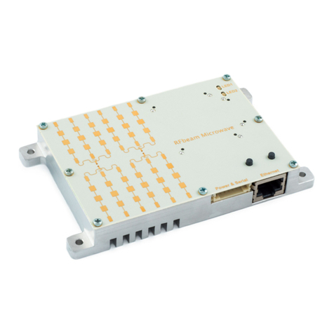
RFbeam Microwave V-MD3 User manual

© RFbeam Microwave GmbH |Schuppisstrasse 7 |CH-9016 St. Gallen |www.rfbeam.ch |V-MD3 |user manual 05/2020 – Revision A |Page 1/16
PRODUCT INFORMATION
– Easy evaluation of the radar sensor V-MD3 over a GUI
– Easy adjustment of parameters for optimization to customer
applications
– Real-time streaming of all relevant radar processing data
– Data recording and playback including video using a webcam
– Firmware update over boot loader
– Saves time to market and reduces NRE costs
– Getting started with the V-MD3
– Real-time optimisation of the radar parameters
fordifferentapplications
– Situation recording including video data
forlateranalysisinthelab
– Learning about the potential of a V-MD3 sensor
The V-MD3 is a high-end 3D radar transceiver with integrated sig-
nal processing and tracking algorithms. It can measure the speed,
direction, distance and angle (in azimuth and elevation) of moving
and static objects. The digital structure and wide power supply
range make it very easy to use this sensor in any stand-alone or
MCU based application.
The control panel described in this user manual allows a simp-
le and quick evaluation of the sensor with all its parameters. All
settings can be easily adjusted in the control panel and the effects
can be verified in real time. The recording function also offers
the option of subsequently playing back and analysing measure-
ments.
Features
Applications
Description
Control Panel
user manual
V-MD3
digital 3D radar transceiver
Figure 1: Control panel GUI overview

© RFbeam Microwave GmbH |Schuppisstrasse 7 |CH-9016 St. Gallen |www.rfbeam.ch |V-MD3 |user manual 05/2020 – Revision A |Page 2/16
TABLE OF
CONTENTS
Product Information ............................ 1
Features ......................................... 1
Applications ...................................... 1
Description....................................... 1
Control Panel..................................... 1
Installation ....................................... 3
Quick Start ...................................... 3
Software update................................ 4
Control Panel ................................... 5
Views ............................................ 6
Miscellaneous Display Controls ................... 10
Modes .......................................... 10
Tabs ............................................ 11
System Requirements ....................... 16
Revision History .............................. 16

© RFbeam Microwave GmbH |Schuppisstrasse 7 |CH-9016 St. Gallen |www.rfbeam.ch |V-MD3 |user manual 05/2020 – Revision A |Page 3/16
INSTALLATION
QUICK START
1. Connect the delivered USB Stick to your PC or
download and unzip the control panel software
from www.rfbeam.ch.
2. Open the installer folder.
3. Install the V-MD3 Control Panel by double clicking
the setup.exe file. If no .net framework is installed,
the installer will install it automatically.
1. Connect the V-MD3 over Ethernet to a hostPC
and change the IPV4 connection settings
onthehost to a static setting with the following
parameters:
IP-Address: 192.168.100.1
Subnet: 255.255.255.0
2. Power up the V-MD3 by applying 12 or 24V on
the pin 1 and GND on the pin 3 of the M12 male
A-coded connector.
3. Start the V-MD3 control panel software.
4. The control panel now tries to ping the V-MD3 on
the default IP address 192.168.100.201. As soon
as the sensor is ready the “Connect” button will
become available.
5. Press the “Connect” button.
6. On a system with multiple webcams, a dialog will
pop up. Select the webcam you want to use.
7. The mode indicator switches to Live stream and
the software is ready to use.
To use the integrated video function, install and
test your webcam before you go to the next
chapter. Please download and install neces-
sary drivers for the webcam from the manu-
facturer website.
At the first start, Windows will ask whether
the firewall should allow communication
connections for the V-MD3 control panel.
Allow it, otherwise the firewall will block
the UDP packets sent from the sensor to
thehost.

© RFbeam Microwave GmbH |Schuppisstrasse 7 |CH-9016 St. Gallen |www.rfbeam.ch |V-MD3 |user manual 05/2020 – Revision A |Page 4/16
SOFTWARE UPDATE
1. Connect the V-MD3 over Ethernet to a hostPC
and change the IPV4 connection settings
onthehost to a static setting with the following
parameters:
IP-Address: 192.168.100.1
Subnet: 255.255.255.0
2. Start the Control Panel and switch to the Soft-
ware update tab.
3. Power up the V-MD3 and wait until the “Connect”
button becomes active. Press the “Connect”
button in the next 4s to connect to the bootloa-
der. The connection was successful if the mode
display changed from Disconnected to Bootloa-
der mode and the bootloader and FPGA version
are displayed.
4. Use the “Browse” button to select the firmware
update file provided by RFbeam Microwave.
5. Press the “Update” button to start the update.
6. Wait until the process has finished. A message
box indicates if the update was successful. The
application starts automatically and by switching
to the communication tab it is possible to directly
connect to the sensor.

© RFbeam Microwave GmbH |Schuppisstrasse 7 |CH-9016 St. Gallen |www.rfbeam.ch |V-MD3 |user manual 05/2020 – Revision A |Page 5/16
CONTROL PANEL
The control panel contains many configuration op-
tions. The structure of the panel views is designed to
guide through the different steps of the radar proces-
sing, which is described in detail in the datasheet of
the V-MD3.
The control panel consists of three different areas
which are described in detail in the next chapters.
Figure 2: Overview control panel areas
Figure 3: Data output example
Views
Miscellaneous
Display Controls
Tabs
There are many views to select in the miscellaneous
display controls area. All of them have a preceded
shortcut based on the data output which is used in
the views (RADC, RFFT, RMRD, PDAT, TDAT). To use
the different views the according data output needs to
be enabled.
For example, if «PDAT – RAW Target Data» is turned
on in the «Data output» section, the views below will
start to visualise the V-MD3 data.
– PDAT – Raw Target Speed/Range
– PDAT – Raw Target Range/Range
– PDAT – Raw Target 3D

© RFbeam Microwave GmbH |Schuppisstrasse 7 |CH-9016 St. Gallen |www.rfbeam.ch |V-MD3 |user manual 05/2020 – Revision A |Page 6/16
Views
The control panel features the possibility to
simultaneously show two views in parallel
to visualise the sensor data in different
ways. How to switch between the different
views is described in the chapter Miscella-
neous Display Controls
Video
If a webcam is connected to the PC it is possible to show
thevideo picture in this view.
To start the video stream the button «Start» needs to be pressed.
RADC – Raw ADC Data
The RADC view shows all sampled ADC channels of the sensor.
Checkboxes:
It is possible to enable and disable the different groups of chan-
nels using the checkboxes.
Recalculate axis button:
Button to recalculate the Y axis of the view.

© RFbeam Microwave GmbH |Schuppisstrasse 7 |CH-9016 St. Gallen |www.rfbeam.ch |V-MD3 |user manual 05/2020 – Revision A |Page 7/16
RFFT – Raw Range-Doppler
The RFFT view shows the raw range Doppler map of one recei-
ving channel. Details about the internal processing can be found
in the V-MD3 datasheet.
RX antenna:
Drop-down list for changing the receiving antenna for the display-
ed data.
Threshold:
Value to change the visualisation colour of the view. Does not
affect the radar settings.
RMRD – Mean Range-Doppler
The RMRD view shows the mean range Doppler map, which is
an averaged and logarithmic map of all four receiving channels.
Details about the internal processing can be found in the V-MD3
datasheet.
Threshold:
Value to change the visualisation colour of the view. Does not
affect the radar settings.
The ADC values are complex values (I-Channel and
Q-Channel). Due to hardware coupling of these channels
targets in the lower half of the distance are seen mirrored
in the upper half of the distance but with less magnitude.

© RFbeam Microwave GmbH |Schuppisstrasse 7 |CH-9016 St. Gallen |www.rfbeam.ch |V-MD3 |user manual 05/2020 – Revision A |Page 8/16
PDAT – Raw Target Speed/Range
This view contains the raw targets found with the same axis as
the mean range Doppler view. The used detection area is also
visualized, which can be configured via the parameters in the de-
tection tab. It is helpful to compare this view with the mean range
Doppler when tuning the detection parameters.
No. of targets:
Count of actually reported raw targets
PDAT – Raw Target Speed/Range
This is one of the most interesting views as the information of the
raw targets is interpreted and shown in a two-dimensional map.
The targets show the radar’s view of the real world. Grey targets
are static targets without any speed. Green targets are moving
away from the radar and red targets are moving towards the
radar.
No. of targets:
Count of actually reported raw targets
Radar direction:
Defines the direction of the radar to the monitor. If «Same as
monitor» is used, the webcam video has to be mirrored to corres-
pond to the data.
PDAT – Raw Target 3D
This view shows the raw targets in three dimensions. The infor-
mation of the azimuth and elevation angles and the target dis-
tance are calculated to the location in a 3D-distance area. The
targets are coloured pins and the colour suits to the Z-dimension
(elevation).
No. of targets:
Count of actually reported raw targets
This view can only display 3D data if the radar setting
uses a 3D setting. Further it can be turned around with
the mouse to change the perspective.

© RFbeam Microwave GmbH |Schuppisstrasse 7 |CH-9016 St. Gallen |www.rfbeam.ch |V-MD3 |user manual 05/2020 – Revision A |Page 9/16
TDAT – Tracking Speed/Range
Compare this view with the corresponding raw view to see the
improvements of the tracking filter and to check the influence of
the tracking settings.
No. of targets:
Count of actually tracked targets
TDAT – Tracking Range/Range
Compare this view with the corresponding raw view to see the
improvements of the tracking filter and to check the influence of
the tracking settings.
No. of targets:
Count of actually tracked targets
Radar direction:
Defines the direction of the radar to the monitor. If «Same as
monitor» is used, the webcam video has to be mirrored to corres-
pond to the data.
TDAT – Tracking 3D
This view shows the tracked targets in three dimensions. The
information of the azimuth and elevation angles and the target
distance are calculated to the location in a 3D-distance area. The
targets are coloured pins and the colour suits to the Z-dimension
(elevation).
No. of targets:
Count of actually tracked targets
This view can only display 3D data if the radar setting
uses a 3D setting. Further it can be turned around with
the mouse to change the perspective.

© RFbeam Microwave GmbH |Schuppisstrasse 7 |CH-9016 St. Gallen |www.rfbeam.ch |V-MD3 |user manual 05/2020 – Revision A |Page 10/16
PDAT, TDAT – Digital Outputs
The sensor has two digital outputs that can be configured to ge-
nerate a detection when an object is in a configurable area. This
view shows a combination of the detection areas for both digital
outputs as well as the PDAT or TDAT targets depending on the
Digital output data setting. Below the view are two indicators that
show the detection status of each digital output.
Modes
The detection parameters for the digital outputs can be
configured in the digital outputs tab.
Miscellaneous Display Controls
The middle of the control panel is used to control which views are
visualised in the views area. It is easy to switch between the diffe-
rent views using the two drop down lists. Further the mode of the
GUI, the actual frame number and the cycle time of the frames is
displayed.
Figure 4: Miscellaneous display controls
Figure 5: Different possible modes Table 1: Different possible modes
It is not possible to display the same view left and right
atthe same time.
Mode Description
Disconnected No connection to the V-MD3.
Live Stream The control panel is connected to the V-MD3 and receives data.
Record Data will be recorded to the PC.
Playback Recorded data will be played and visualised.
Bootloader The control panel is connected to the boot loader of the V-MD3
and the sensor is ready for a software update.

© RFbeam Microwave GmbH |Schuppisstrasse 7 |CH-9016 St. Gallen |www.rfbeam.ch |V-MD3 |user manual 05/2020 – Revision A |Page 11/16
Tabs
This chapter describes the different control
tabs of the software. It is possible to con-
trol all the parameters of the V-MD3 and
all the functions of the control panel over
these tabs.
A more detailed parameter description of the sensor can be
found in the datasheet of the V-MD3.
Communication
Figure 6: Communication tab
To connect to the sensor, the correct server IP of the V-MD3
sensor must be entered. After starting the control panel, the
“Connect” and “Disconnect” buttons are greyed out. The control
panel tries to ping the sensor with the defined IP address in the
Server IP field and activates the “Connect” button as soon as the
ping to a V-MD3 under the server IP address was successful.
If a V-MD3 is connected, this indicator shows information about
the firmware and FPGA version of the sensor.
Select which output is sent from the radar to the control panel.
The according views can only show data if the corresponding
data outputs are enabled.
TCP Application
Info
Data Output
It may take up to 60 seconds for the “Connect” button
to activate. This depends on the network environment
used.
If the sensor is in live stream mode after a successful
connection and the corresponding data outputs are
activated but no data is shown in the views, check the
firewall settings. The control panel must have communi-
cation rights in the Windows firewall.

© RFbeam Microwave GmbH |Schuppisstrasse 7 |CH-9016 St. Gallen |www.rfbeam.ch |V-MD3 |user manual 05/2020 – Revision A |Page 12/16
Radar
Detection
Figure 7: Radar tab
Figure 8: Detection tab
This tab controls the main setting of the processing chain in the
radar sensor. By changing the settings parameter it is very easy to
adapt the sensor to the needs of an application and check the in-
fluences in real time. A detailed description of all settings and the
influences to the processing stages can be found in the chapter
Radar settings of the V-MD3 datasheet.
It is important to use a setting with distance and speed ranges
that match with the distance and speed of the expected targets in
the detection area of the sensor.
The detection tab controls mainly the detection filter which can be
used to control the number of PDAT raw targets. It makes sense
to use the RMRD – Mean Range Doppler view together with the
PDAT – Raw Target Speed/Range view when you change settings
in this tab because it visualises directly the used settings of the
filter and the generated outputs of the PDAT structure. A detailed
description of all parameters can be found in the chapter Detec-
tions Settings of the V-MD3 datasheet.
Wrong settings can generate
false sensor outputs. It is pos-
sible that strong targets out-
side the configured distance or
speed range can create false
reflections.

© RFbeam Microwave GmbH |Schuppisstrasse 7 |CH-9016 St. Gallen |www.rfbeam.ch |V-MD3 |user manual 05/2020 – Revision A |Page 13/16
Tracking
Digital Outputs
Settings
Figure 9: Tracking tab
Figure 10: Digital outputs tab
Figure 11: Settings tab
On the Tracking tab you can control the tracking settings, which
are described in the chapter Tracking settings in the V-MD3
datasheet. It makes sense to use the PDAT – Raw Target Range/
Range view together with the TDAT – Tracking Range/Range view
or the corresponding 3D views if a 3D radar setting is used when
changing these settings.
On this tab you can control the digital outputs settings, which
are described in the chapter Digital outputs in the V-MD3 datas-
heet. The use of this tab together with the PDAT, TDAT – Digital
Outputs view allows for a simple and intuitive adjustment of the
detection areas for the digital outputs.
On the Settings tab you can easily save and reload the complete
settings of a sensor. This makes it simple to duplicate a useful
data set on multiple sensors. It is also possible to restore the
factory settings and change the sensor‘s IP address.
By changing the radar server IP, multiple sensors can be
connected to the same host. The control panel dyna-
mically processes the UDP port settings of the sensors
when connecting to multiple sensors.
It is not possible to change the
IP address to the fixed IP of the
bootloader (192.168.100.200).

© RFbeam Microwave GmbH |Schuppisstrasse 7 |CH-9016 St. Gallen |www.rfbeam.ch |V-MD3 |user manual 05/2020 – Revision A |Page 14/16
Record/Playback
Figure 12: Record/Playback tab
To record data, you first need to specify a path where to store
the data on the PC. By selecting the Store video checkbox it is
possible to also store a picture per frame from the webcam. The
recording of the data can then easily be controlled over the Start
and Stop button.
The software creates for every recording a new subfolder with a
timestamp of the recording in the selected folder and stores there
a raw binary file with all received sensor data packets and the
video pictures when selected. Refer to the datasheet for detailed
information about the packet structure, commands and messa-
ges in the stored binary file.
To playback the recorded data, the control panel must be dis-
connected. By selecting a folder of a recorded sequence it is
possible to start, stop and pause a recording by a controlled cycle
time. Even the start of the frame number in the recorded data can
be chosen.
The playback feature is a very powerful tool to do an in depth
analysis of the recorded data. It gives the possibility to compare
the recorded data easily in all available views when the according
data output was enabled for the recording.
Record data
Playback data
The record feature records the complete data output
of the sensor specified in the communication tab under
Data output. The performance of the recording may vary
based on the following circumstances:
– Performance of the used PC
– Use of the video capture feature
– Enabled data output
This tab can be used to record and play-
back the sensor data to the hard disk. It
is also possible to store the video data in
parallel what can be helpful to interpret the
measured data in the playback mode.

© RFbeam Microwave GmbH |Schuppisstrasse 7 |CH-9016 St. Gallen |www.rfbeam.ch |V-MD3 |user manual 05/2020 – Revision A |Page 15/16
Software update
Figure 13: Software update tab
This tab allows the update of the V-MD3 firmware over Ethernet.
It can also be used to completely reset a sensor to the default
values if it has an unknown programmed IP address because the
IP address of the bootloader is fixed to 192.168.100.200.
A step by step instruction how to update the firmware
can be found in the chapter Software update on page4.
Use only firmware update files provided
byRFbeamMicrowave.
After starting the control panel, the „Connect“ and „Disconnect“
buttons are greyed out. The control panel tries to ping the boot-
loader of the sensor at the fixed IP address 192.168.100.200. A
connection to the bootloader is only possible after a power cycle
of the sensor. If the control panel can successfully ping the boot-
loader, it activates the „Connect“ button for 4 seconds before the
button is greyed out again because the sensor has left the boot-
loader and started the application software. A detailed description
of how the bootloader works can be found in the chapter Boot-
loader in the V-MD3 datasheet.
If the control panel is connected to the bootloader, its version
and the FPGA version are available in the corresponding fields. It
is possible to select a hex file using the „Browse“ button and to
update then the sensor firmware using the „Update“ button.
TCP Bootloader
Software update

© RFbeam Microwave GmbH |Schuppisstrasse 7 |CH-9016 St. Gallen |www.rfbeam.ch |V-MD3 |user manual 05/2020 – Revision A |Page 16/16
Graphical
Figure 14: Graphical tab
This tab offers the possibility to open a second window with a full
screen view. Only the left view or a view with both views can be
opened via the two “Full screen” buttons.
REVISION HISTORY
05/2020 – Revision A: Initial Version
SYSTEM REQUIREMENTS
– Windows 7 or Windows 10
– .NET Framework 4 Client Profile
Table of contents
Other RFbeam Microwave Transceiver manuals
Popular Transceiver manuals by other brands

Technisonic Industries Limited
Technisonic Industries Limited TFM-566 Installation and operating instructions

Yaesu
Yaesu FT-230R instruction manual

Crestron
Crestron CWD6922 Operation guide

Microwave Data Systems
Microwave Data Systems MDS 2710D Installation & operation guide

HME
HME NEXEO HDX RT7000 Quick Reference Installation Guide

Alinco
Alinco DJ-580T instruction manual