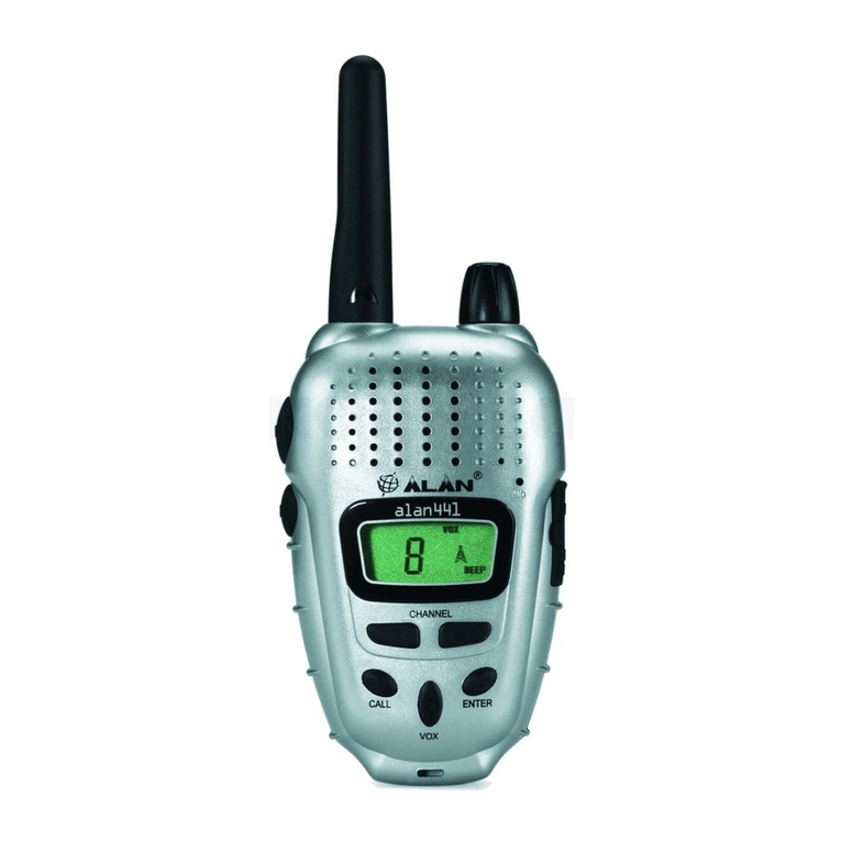
Alan HP70L User manual

HP70L / HP70HServiceManual
ALANHP70L/ HP70H
PortableVHFTransceiver
Service Manual
Copyright 2006 byCTEInternationalItaly. Allrightsreserved

HP70L / HP70HServiceManual
Contents
1TECHNICALSPECIFICATIONS....................................................................................................................3
1.1Testmethods.........................................................................................................................................................................3
1.2Specificationstable..............................................................................................................................................................3
2CIRCUITDESCRIPTION...............................................................................................................................4
2.1General information...............................................................................................................................................................4
2.2Microprocessor/control .........................................................................................................................................................4
2.3VCO/Synthesizer(PLL).....................................................................................................................................................4
2.3.aTemperature-CompensatedCrystalOscillator(TCXO).........................................................................................4
2.3.bVoltage-ControlledOscillators(VCO).....................................................................................................................4
2.3.cSynthesizer..............................................................................................................................................................5
2.3.dLoopFilter...............................................................................................................................................................5
2.4Transmitter...........................................................................................................................................................................5
2.4.aRF PowerAmplifier.................................................................................................................................................5
2.4.bAntennaSwitching..................................................................................................................................................5
2.4.cPowercontrol...........................................................................................................................................................5
2.4.dTransmitterAudioCircuits.......................................................................................................................................6
2.4.eAudio Processing....................................................................................................................................................6
2.5Receiver...............................................................................................................................................................................6
2.5.aReceiverFront End.................................................................................................................................................6
2.5.bLocalOscillator(LO)...............................................................................................................................................6
2.5.cMixer........................................................................................................................................................................6
2.5.dFMDetectorandSquelch.......................................................................................................................................6
2.5.eReceiverAudioCircuit.............................................................................................................................................6
2.6Signalling...............................................................................................................................................................................7
2.6.aGeneral....................................................................................................................................................................7
2.6.bCTCSSToneEncoder/DigitalCodeSquelch(DCS) Encoder.............................................................................7
2.6.cSelectivecall ............................................................................................................................................................7
2.6.dScrambler................................................................................................................................................................7
2.7Battery..................................................................................................................................................................................7
3ADJUSTMENTSHP70L.................................................................................................................................8
3.1General .................................................................................................................................................................................8
3.2NeededEquipment:..............................................................................................................................................................8
3.3Programmingtheradio.........................................................................................................................................................9
3.4Synthesizer/TransmitterVCOCheck..................................................................................................................................9
3.5FrequencyAdjustment.........................................................................................................................................................9
3.6TransmitterAlignment..........................................................................................................................................................9
3.6.aPowerAdjustment...................................................................................................................................................9
3.6.bModulationAdjustment.........................................................................................................................................10
3.6.cCTCSS/DCSadjustment........................................................................................................................................10
3.6.dSelcalmodulationadjustments..............................................................................................................................10
3.7ReceiverAlignment............................................................................................................................................................10
4ADJUSTMENTSHP70H..............................................................................................................................12
4.1General ...............................................................................................................................................................................12
4.2NeededEquipment:............................................................................................................................................................12
4.3Programmingtheradio.......................................................................................................................................................13
4.4Synthesizer/TransmitterVCOCheck................................................................................................................................13
4.5FrequencyAdjustment.......................................................................................................................................................13
4.6TransmitterAlignment........................................................................................................................................................13
4.6.aPowerAdjustment.................................................................................................................................................13
4.6.bModulationAdjustment.........................................................................................................................................14
4.6.cCTCSS/DCSadjustment........................................................................................................................................14
4.6.dSelcalmodulationadjustments..............................................................................................................................14
4.7ReceiverAlignment............................................................................................................................................................14
4.8Figure1-Test adaptor......................................................................................................................................................15

HP70L / HP70HServiceManual
1TECHNICALSPECIFICATIONS
1.1Testmethods
§ ETS300-086
§ IEC529IP54andMILSTD810 C/D/E
1.2Specificationstable
GENERAL
Frequency ALANHP70 L:66÷77MHz
ALANHP70 H:77 ÷88 MHz
Operationalbandwidth 11 MHz
Numberofchannels 16
Channelspacing 12,5/20/25kHz
Channelincrease 5/6,25kHz
Powersupply Ni-MHBattery1300mA/h7.5VDC
Antenna impedance 50 Ohm
Loudspeakerimpedance 8Ohm
Frequency stability ±2.5ppm
Temperaturerange, operative Minus30° Ctoplus60°C
TRANSMITTER
Outputpower Low1.0W, High5.0W±1dB
Spuriousemissions <0.25µW9KHz÷1GHz;<1µW1÷4GHz
Modulationsystem F3E(FM)
Modulation ±2,5/ ±5kHz
Audiodistortion 5%maximum
Maximumdeviation ±2.5kHz/ ±5kHz
Adjacentchannelpower -60dB/-70dB
RECEIVER
Circuittype Doubleconversion,IF1=45.1MHz, IF2=455kHz
Sensitivity 0.35µVmax.@ 12dBSINAD
Squelchsensitivity 10dBSINAD
Adjacentchannelselectivity 65 /75dBmin.
Spuriousrejection 70dB
Intermodulation 65 dB
Humand NoiseRatio -45dB/<-40dB
Outputaudio 400mWa5%T.H.D.(@1KHz)
MECHANICALSPECIFICATIONS
Dimensions 130 x42x60mm (batterypackincluded)
Weight 355 gr(batterypackincluded)
Battery Back slidebattery
Accessory/programming connector Jack mono
Wateranddust IEC529IP54

HP70L / HP70HServiceManual
2CIRCUITDESCRIPTION
2.1General information
The information inthissection iscommon forbothHP70L and HP70H radios.
The HP70L/Hcircuitryisdivided inthe following sections, pleaserefertothe Block Diagramand
SchematicDrawings.
§ Microprocessor/Control
§ VCO/Synthesizer
§ Transmitter
§ Receiver
§ Signalling
§ Battery
2.2Microprocessor/control
ThemicroprocessorQ17 is16 bitmicrocontroller, equipedwithan internalRandomAccess Memory(RAM)and a
re-programmableFlashProgram/Datamemory.It isconstantlyoperating whentheradioisturnedON,
monitoring thekeyboard, channelswitch, thePTT lineand otherinternalinputssuchasthesquelchdetect input,
PLL Locklineetc..Whenachangeoccurs,themicroprocessormakestheappropriateresponse.The
microprocessorrunsoffan 8MHzcrystaloscillatorwhichiscomposedofX1,C30,C31,R48and an internal
logicalinvertercircuit.Thechanneldata–frequency, modulationarestoredinanexternalnonvolatileEEPROM
Q8.
Whentheradioisfirstturnedon,themicroprocessorreadstheradiostatusfromtheEEPROMQ8.The
microprocessordeterminesthereceivefrequency codes,thenloadsthesynthesizerviaitspins42 (PLLLE),46
(PLL CLK)and43 (PLLDATA),controlstheReceive/Transmit switchesetc.
2.3VCO / Synthesizer(PLL)
Thissection basicallyconsistsoftheTemperature-CompensatedCrystalOscillator(TCXO),VoltageControlled
Oscillators(VCOs),PLLSynthesizerand thePLLLoopFilter.
2.3.aTemperature-CompensatedCrystalOscillator(TCXO)
Thereferenceoscillator(X401)isacrystaloscillator.RV402 isusedtoadjusttheoscillatorfrequency tothe
nominalfrequency of14.400 MHzatroomtemperature(22 degC).Thereferenceoscillatorisheldwithin±2.5
PPMintheworking-30to+60degCtemperaturerangebyaninternaltemperaturecompensationcircuit.
2.3.bVoltage-ControlledOscillators(VCO).
RadioincorporatestwoseparateVCOs.Onlyoneofthe VCOsrunsatatime,whichiscontrolledby
microprocessorQ17.WhenthePTT ispressed(Transmitmode),Q17pin34goeslow,disablingthereceive
VCObytheQ420 and biaseson Q419 toenablethetransmitterVCO. WhehPTT isreleased(ReceiveMode),
Q17pin34linegoeshigh,enablingReceiveVCOtrough Q420anddisabling TXVCOtroughQ419.
TheReceiveVCOtankconsistsofcapacitorsC482-C485,CV401, InductorL426-L428,JFETQ422 andvaricap
diodesQ423 andQ424.ThisVCOoscillatesat45.1MHzabovetheprogrammedreceivefrequency.TheVCO’s
oscillating frequency istunedbythevaractorsQ423 andQ424.Thetuning voltageissuppliedfromtheoutputof
thePLL Loop Filter.Theoutputof theVCO isACcoupled(C475 and R558,C530,C505)tothePLL synthesizer
and theoutputamplifierrQ414respectively.
TheTransmitterVCOtankconsistsof C487,C489-C491, CV402,L424,L425, L429 and Q416-Q418.
ThisVCOoscillateson theprogrammedtransmitfrequency.TheVCO’soscillating frequency istunedbythe
varactorsQ417and Q418.ThetuningvoltageissuppliedfromtheoutputoftheLoopFilter.Theoutputofthe
VCOisACcoupled(C486)tothesynthesizerinput bufferQ428 and theoutput bufferQ415 respectively. Varactor
diodeQ1toghetherwithaccosiatedcircuitryallowsTransmitVCOtobefrequency modulatedtrough TX_MOD
line.

HP70L / HP70HServiceManual
2.3.cSynthesizer
Thefrequency synthesizerisalargescalemonolithicintegratedcircuitQ429.
RFoutputfromtheactive(ReceiveorTransmit)VCOiscoupledtothesynthesizerprescalerinput at Pin8. The
divide-by-NcounterchaininQ429,consistingofthedual-modulusprescaler, swallowcounterand programmable
counter,dividestheVCOsignaldowntoafrequency verycloseto5.00 KHzor6.25 Khz,depending on channel
frequency, whichisappliedtothephasedetector.Thephasecomparatorcomparesthephaseof thissignalwith
that of the5.00 KHzor6.25 KHzreferencesignalfromthereferencedividerand drivestheexternalchargepump
(Q425 and Q426).
Thesynthesizerunlock detectorcircuitpreventstheoperationofthetransmitter,whenthephaselock loop (PLL)
isunlocked. Thefollowing discussion assumestheunit hasbeenplacedinthetransmitmode.Q429 lockdetector
Pin7goeshigh whenthe PLL islocked.Thishigh levelisappliedtoPin21 ofthemicroprocessorQ17.A
softwaretimingroutingbringstheRX/TXlinelow(Pin29 ofQ17),feeding thissignalthroughtheswitch/buffer
Q15.WiththeRX/TXlinelow,Q223Aiscutoffand Q223Bisbiaseson passing+5VTXtoQ431B,itbiaseson
Q430topassswitchedTXB+tothetransmitteramplifierstringwhichenablestransmission.
WhenthePLL becomeunlocked,thelock detectoratQ429Pin7 will beginpulsing low.ARC circuitconverts
pulsing lowtoalowlevelforthemicroprocessor.ThemicroprocessorthenchangestheRX/TXlinetoahigh,
forcing Q430 intocutoff whichdisabletransmission.Thetransmitterremainsdisabledwhiletheloop remainsout
oflock.
2.3.dLoopFilter
TheLoop Filter,apassivelead-lag filterconsisting ofR461-R464 and C493-C495,integratesthechargepump
outputtoproducetheDC turning voltagefortheVCO. DirectFMisobtainedformodulating frequenciesoutside
thePLL bandwidthbyapplyingtheCTCSS/DCSsignalsandthepre-emphasized, limitedmicrophoneaudiotothe
VCOmodulation circuit.
Themodulationcircuitconsistsof R452, Q421andC487.
2.4Transmitter
2.4.aRFPowerAmplifier
AfterthePTTispressed, the+5VTXlineswitchestoapproximately5V.Q419 isturnedonenablingtransmitVCO.
TheVCObuffer,pre-driver,driverand poweramplifierarebiasedon byQ430,whichisbiasedon bythe+5VTX
lineswitchingto5V. RFoutputfromthetransmit VCO(Q416)isappliedtotheVCO outputbufferQ415.
OutputfromQ415 feedsthe pre-driveramplifierQ413.TheoutputsignalfromQ413 feedsthedriveramplifier
Q412,whoseoutputfromthedriverstagefeedsthefinalRFpoweramplifierQ407 toproducetheratedoutput
powerof5watts.Theoutputofthefinalisappliedtoalow-pass filter(C451,C452 and L413)and thentothe
transmit/receiveswitchQ402.RFpoweristhenfedtotheantenna viatheoutputlow-pass filterconsisting of
C401,C403, C405-C408,L401,andL402.
2.4.bAntennaSwitching
Switchingoftheantenna betweenthetransmitterandthereceiverisaccomplishedbytheantenna
transmit/receiveswitchconsisting ofdiodesQ401 andQ402inconjunction withC410 andR402.Inthetransmit
mode,switchedTXB+isappliedthrough R420 and RFchokeL414,hardforwardbiasing thetwodiodeson.Q402
thuspermitstheflowofRFpowerfromoutputofthelow-pass filterfedbytheoutputamplifiertotheoutputlow-
pass filter. Q401 shortsthereceiverinputtoC410,whichisACcoupledtoground.L403,C409,C410 and R402
thenfunction asalumpedconstantquarter-wavetransmission line,thuspresenting ahighimpedancetotheRF
output path,effectivelyisolating thereceiverinputand transmitteroutputsections.
2.4.cPowercontrol
OutputpoweriscontrolledviathedualOp-Amp(Q408),whichisusedasadifferentialamplifierandcomparator.
Currentissensedbythevoltagedrop acrossR421 and R422.Thisvoltageiscomparedtotheonesetbythe5
wattAdjustmentRV401.ThepoweroutputisthenreducedorincreasedbyvaryingtheQ410'soutputvoltage
appliedtothepoweramplifierQ407'spin2.

HP70L / HP70HServiceManual
2.4.dTransmitterAudioCircuits
Thetransmitteraudiocircuitsconsist oftheaudioprocessingcircuits,theCTCSS circuitsand theDCScircuits.
2.4.eAudioProcessing
Transmitspeedaudioisproviding byeithertheinternalelectricmicrophoneN101 ortheexternalmicrophone.
ThemicrophoneaudioisappliedtoMICMUTESWQ235,and Lo-pass filterQ214A,Q214B.Theaudioispre-
emphasizedby6dBperoctavebyC236 and R284,and thensignalamplification.Thegainissuchthatasignal
20dBgreaterthan 2nominallevelislimited.Undertheseconditions,theMOD.ADJ.PotRV201isusedtoset
maximumdeviation.Theresulting signalisthenfrequency limitedwiththeaidofaLPF,and hasan 18 dBper
octaveroll-off above3kHz.
Theaudioisthenappliedthrough the25 kHz/12.5kHzchannelspacingSWQ215totransmitVCO.Byvarying
thevoltageon thediodeQ921 atan audiorate,theresonantfrequency ofVCOisvaried.Theresultisan
oscillatoroutput that isfrequency -modulatedattheaudiofrequency.
2.5Receiver
2.5.aReceiverFrontEnd
Inthereceivemode,theRFsignalentersthorough theantenna,thenthrough thelow-pass filterC401,C403,
C405-C409 andL401-L403.ThediodesQ401 and Q402arebiasedoffsothattheoutputofthelow-passfilteris
coupled(C411)tothefirst band-passfilterC412-C415, C417-C420,L404-L407 and totheFront EndRFoverload
protectiondiodepairQ403. Thesignalfromtheband-pass filterisappliedtotheinputoftheRFamplifierQ404.
TheoutputoftheRFamplifierfeedstheinputtothree morestagesofband-pass filtersconsisting ofC424-C431,
and L408-L410.Theoutputfromtheband-passfilterisappliedtothepassivemixer’sQ405/L411.
2.5.bLocalOscillator(LO)
TheReceiveVCO(C482-C485,CV401,L426-L427,Q422-Q424 andR453-R454)providestheLOsignal.The
VCOisrunning at 45.1MHzabovethedesiredreceivefrequency and isappliedtooutputBufferQ415/Q414.The
outputofthebufferthrough thelow-pass filterC433-C435,L432-L433 isappliedtotheLOportofthemixer
Q405/L411/L412.
2.5.cMixerandIF
ThemixerisaDBMtype(L411,Q405,L412). Whenthereceiverfrequency ispresent, themixeroutputwill bea
45.1MHzsignal.Themixeroutputispeakedfor45.1MHzatL434,C437 and R413,and thesignalisfilteredby
crystalfilterF401AandF401Band amplifiedbyQ406beforebeing appliedtotheinputoftheIFICIC6.
InsideIC6,the45.1MHzIFsignalbecomestheinputtoasecond mixerwithaLOfrequency of44.645MHzset by
X201.The455 kHzceramicfilterF201 orF202 filtersthesecond mixer’soutputwhichisthesecond IFsignal.
Themixer’soutputisthenfedtotheinternallimitingamplifierand thenontotheFMdecoder.
2.5.dFMDetectorandSquelch
TheFMdetectoroutputisusedforsquelch,decoding tonesand audiooutput.Thesetting ofthesquelch
adjustmentpotentiometerRV204 (for25 kHzchannelspacing)and RV205 (for12.5kHzchannelspacing)sets
theinputtothesquelchamplifier.ThesquelchamplifierisinternaltoIC6and itsoutputisfedtoaninternal
rectifierandsquelchdetector.
Theoutput onIC6Pin14signalsthemicroprocessorQ17withalowlevel(0V)toun-mutetheradio.
Theaudioisun-mutedbythemicroprocessorQ17 Pin27 switchingtoahigh value(3.3Von SQLMUTE)thus
biasingonQ206. TheaudioisthenroutedtotheaudioamplifierQ221viathevolumecontrolS201.
2.5.eReceiverAudioCircuit
Thedetector’saudiooutput alsoisfedtothetone(CTCSS andDCS)low-passfilterQ212C.
Thentheoutputofthelow-passfilterisroutedtothesecond stagefilterQ212B.TheoutputofQ210Bisappliedto
thesquaringcircuit Q212AandfinallytothemicroprocessorQ17Pin60fordecoding.
Anotherbranchingofthedetectoroutputfeedstheaudiohigh-pass filterQ208 viaQ212D.Theoutputofthe
audiohigh-pass filterfeedstheVolumeControlS201(VOL).FromthewiperarmontheVolumeControl, theaudio

HP70L / HP70HServiceManual
isroutedtoPin2,theinputtotheaudiopoweramplifierQ221.Theoutputoftheaudiopoweramplifierisrouted
through theearphonejackJ401totheinternalspeakerE101.
2.6Signaling
2.6.aGeneral
ThemicroprocessorisfittedwithaADC/DACconverterbuilt-in,soitprovidesgenerating anddecoding thetones
forselectivecalls,CTCSS and DCS.It can do thatwithoutusing anyotherexternalICs,butonlybymeansof
sometransistors. ThedeviationoftheselectivecallcanbeadjustedbythetrimmerIRV1.
Themicroprocessormanagestheanalogueswitchesforthe scrambleraswell,whichisbase-band-inversion
type.
2.6.bCTCSS ToneEncoder/ Digital CodeSquelch(DCS)Encoder
CTCSS signalsand DCSsignalsaregeneratedbymicroprocessorQ17.CTCSS appearaspulsewide
modulatedsignalatatPin39.ThesameI/O lineisusedasDCSrectangularwaveformoutputand isapplied
tothetransistorIQ5whichmakesthesignalsclosertothetheoreticCTCSS/DCSsignals.Thewaveformisthen
smoothedbylowpassfiltersQ213Btoproducean acceptablesinewaveoutput.TheCTCSS tonesignalisadjust
totheproperlevelbyRV202.TheDCSsignalisadjusttotheproperbalancebyRV203.Thesignalisthen
appliedtotheaudioprocessingcircuit atR305 andtotheTCXOcircuit atX401.
2.6.cSelectivecall
SimilarlytoCTCSS/DCS, selcallsignalsarealsogeneratedand decodedbythe microprocessorQ17. Theselcall
decodeinputisthepin59 (ADC_SELCALL),whilsttheTXtonesaregeneratedatpin37,SELCALL_PWM.
PulseWideModulatedsignalfrompin59isfedtothetransistorQ4and associatedcircuitry,whichforman 3kHz
LowPassFilter.RV1adjuststhelevel(deviation)ofthetones.
2.6.dScrambler
HP70 containsainversion scrambler.Theaudiobaseband AFTX_IN(Fbb=300 to3000Hz)ismixedwitha
3333Hzfixedfrequency carrier(SCRMBLR_CLK)generatedbythemicroprocessorQ17inaDoubleBalanced
Mixer(switchesAand BofthemultiplexerICQ3and OperationalamplifiersQ1Aand Q1C). Themixer’soutput
ispassedtrough alow-pass filter,buildaround Q1Band Q1CtoAFTXoutputline.Thisscrambledvoicesounds
garbled,whenreceivedbynormalreceivers.However,ifthe scrambledtransmission isreceivedbytheparty’s
HP70 withscrambledactivated,thescrambledreceiverbaseband AFRXisfedtothescramblerunitand mixed
withthesamefixedcarrier,generatedbythemicroprocessor.TheoutputofthemixerAFRX_OUTwillbea
normal(unscrambled)basebandandcanbeclearlyheard.
ThestandardInversionCarrierfrequency, usedinHP70 is3333 Hz,howeveradifferent tonecan berequired.
2.7Battery
Thebatteryconnectstothecontactpins(CN201 and CN202)on thebottomend oftheRadio.Thepositive
terminalofthebatteryconnectstotheON/OFF VolumeControlswitch(S201)and thenegativeterminalconnects
tochassisground. LowbatterysenseR101/R102,voltageregulatorQ222andtransmitpowermoduleQ407.
ThebatteryvoltagestatusismonitoredbythemicroprocessorQ17 Pin61 whichsensesthebatteryvoltage
through theBATT+SWlinebymeansofR51/R49.Whenthebatteryvoltageisapproximately5.8V,the
microprocessorconsidersthebatterydischargedandswitchesoffthecircuitsoftheradio.
WhentheRadioison achannelwithno toneprogrammed,theBATTERYSAVERModeisenabledwhen
programmed.
IntheBATTERYSAVERmode,themicroprocessorQ17generatesasquarewavesignalatPin48whichis
appliedtotheinverterQ10:6.Thesignal’sdutycyclevariesaccordingtowhatthePOWERSAVE TIMERisset.
WhenthemicroprocessorQ17 Pin48goeshigh (approx.5V)Q226 (receivermodule)isbiasedoff,Q225is
biasedon,Q224Aiscutoff,andQ223Aiscutoff,thusturningthesupplyofftoIC6.

HP70L / HP70HServiceManual
3ADJUSTMENTSHP70L
3.1General
Adjustmenttrimmerpotentiometer/capacitorsintheHP70VHFRadio:
Ref.Designator
Usedfor…
RV204 SquelchLevelAdj.,25kHz(wideband)spacing.
RV205 SquelchLevelAdj.,12.5kHz(narrowband)spacing.
RP402 FrequencyAdj.
RV201 Deviation Adj.
RV202 CTCSS Deviation Adj.
RV203 DCSBalanceControl.
RV1 Selcall deviation Adj.
RV401, C1008 TransmitterHighPowerAdj.
RV405 TransmitterLowPowerAdj.
CV401 ReceiverVCOAdj.
CV402 TransmitterVCOAdj.
3.2NeededEquipment:
§ 7.5V/3ADC Regulated PowerSupply;
§ DC Ammeter,5Amin.;
§ Test Adapter(Figure1below);
§ Digital DC Voltmeter;
§ AF Voltmeter(see noteA);
§ Distortion Meter(see noteA);
§ AudioSignal Generator(600Ohm)(see noteA);
§ RF SignalGenerator(see noteA);
§ RF Watt-meter,upto10W(seenoteA);
§ UHF FrequencyCounter(see noteA);
§ FMLinearDetector(see noteA);
§ Oscilloscope(see noteA)
2 NoteA: Usuallyincluded in specializedCommunication Tester(R&SCMT forexample)

HP70L / HP70HServiceManual
3.3Programmingtheradio
1)Programtheradio,asfollows:
ChName
RxFreq
TxFreq
ChSpace
Pwr
Dcs/CtcssRx Dcs/CtcssTx SelCall Rx Transpond Call1 Call2 Emergency
MonKey
Ch.1 66.050
66.075
25
H
Ch.2 71.050
71.075
25
H
Ch.3 76.950
76.975
25
H
Ch.4 66.050
66.075
12.5
L
Ch.5 71.050
71.075
12.5
L
Ch.6 76.950
76.975
12.5
L
Ch.7 71.050
71.055
25
L CTCSS:67HZ CTCSS:67HZ
Ch.8 71.050
71.055
25
L CTCSS:100HZ
CTCSS:100HZ
Ch.9 71.050
71.055
25
L CTCSS:250.3 CTCSS:250.3
Ch.10 71.050
71.055
12.5
L CTCSS:67HZ CTCSS:67HZ
Ch.11 71.050
71.055
12.5
L CTCSS:250.3 CTCSS:250.3
Ch.12 71.050
71.055
25
L DCS:23 DCS:23
Ch.13 71.050
71.055
25
L DCS:627 DCS:627
Ch.14 71.050
71.055
12.5
L DCS:23 DCS:23
Ch.15 69.225
69.225
25
L ZWEI1,RX#1
ZWEI1,TX#1
ZWEI1,TX#1
ZWEI1,TX#2
ZWEI1,TX#3
SelCall
Ch.16 69.225
69.225
25
L CTCSS:114.8 CTCSS:114.8
ZWEI1,RX#1
ZWEI1,TX#1
ZWEI1,TX#1
ZWEI1,TX#2
ZWEI1,TX#3
SelCal
DCS
Forthelocationofthecomponentscalledoutinproceduresbelow,refertoPCBdrawings.
3.4Synthesizer/TransmitterVCO Check
1)Connectthean electronicvoltmeterbetweenTP6andGround.
2)Switchtochannel 3
3)TuneCV401 inReceivemodefor2.35V± 0.05Vat TP6.
4)Switchtheradiotochannel 1.CheckthevoltageatTP6,itmustbebetween0.6and0.9V
5)Switchtheradiotochannel 3.
6)PushthePTT switch(TX)andtuneCV402for3.15V± 0.05VatTP6.
7)ReleasethePTT. Switchtheradiotochannel 1.
8)PushthePTT switch(TX)andcheckthevoltageat TP6,itmustbebetween0.7and0.9V.
3.5FrequencyAdjustment
1)Switchtheradiotochannel3
9)PushthePTT. Adjust RV402 foraFrequencywithin± 500Hzoftheprogrammed transmit frequencyof76.975MHz
3.6TransmitterAlignment
2 NOTE:Inordertoobtain propertransmission outputpower,connectthe Radio tothe powersupplywithacable thatisrated
towithstandacurrent of 2amperesorgreater.
3.6.aPowerAdjustment
1)ConnecttheRadioinaccordancewithFigure1.
10)Switchtheradiotochannel 1
11)PlacetheunitinHIGHPOWERmode.
12)TurnRV401andRV405fullyclockwise.
13)OperatethetransmitterRF outputpowerreadingon thewattmetermust be5.5Worgreater.

HP70L / HP70HServiceManual
14)AdjustRV401(HIPWRADJ)and C1008forareading of4.9W ±0.1W.Checktomakesurethatthetransmitcurrentis
within 1000-1400mAaftertheadjustmenthasbeen made.Checkthepoweron channels2and3.It mustbebetween 4.3
and5.5W.
15)Switchtheunit tochannel 4(LOWPOWER).
16)AdjustRV405(LOPWRADJ)forareadingof1.2W ±0.1W.Checktomakesurethatthetransmitcurrentiswithin 500-
700mAaftertheadjustmenthasbeenmade. Check thepoweronchannels5and6. Itmustbebetween0.8and 1.5W.
3.6.bModulationAdjustment
1)SwitchtheRadiotochannel 1
17)Applya1kHztonesignal toTest Adapter'sAF Input(Figure1),whichisthemicrophoneimpedancematching network;
18)PlugtheTestAdapterintotheexternalspeaker/microphonejack.Settheaudiogenerator'soutputlevelatapproximate
300mVrmsat TPAoftheTestadapter;
19)Operatethetransmitter, andadjustRV201(MOD.ADJ)for4.0±0.1kHzdeviation;
20)Check thedeviation on channels2and3.It must bebetween3.8and 5kHz.
21)Check thedeviation onchannels4,5and6(narrowband).Itmustbebetween1.8and2.5kHz
3.6.cCTCSS/DCSadjustment
2 BeforeadjustingCTCSSand DCSDeviation,besuresettingsin 3.6b abovearedone properly.
1)SettheCommunication TesterFMlineardetectoraudiobandwidthlowfrequencylimittoDC or0.25 Hzorless .Set
detectorhighfrequencylimit to15,000 Hzormore.TurntheCommunication Testerde-emphasisfunction off.
22)SwitchtheradiotoChannel12.Operatethetransmitter,and adjusttheDCSbalancecontrol RV203 toaclearwave,as
shownbelow.
23)Switchtheradiotochannel 11. Operatethetransmitter.Adjust RV202foradeviationof300±50Hz.
24)Apply1kHz,300mVaudiosignal atTPA ofthecheckadapter.Checkthedeviation on channels7,8and 9.It mustbe
between3.8and5kHz.
25)Switchtheradiotochannels10 and11. Checkthemaximumdeviation.It must bebetween 1.8and2.5kHz.
26)Check thedeviation on channels12and 13. Itmustbebetween3.8and5kHz.
27)Check thedeviation on channel 14. Itmustbebetween1.8and2.5kHz.
3.6.dSelcall modulation adjustments
1)SwitchtheradiotoChannel 15.
28)PushRadio'sMonitorKey.
29)WiththeaidofRV1adjustthedeviation between 2.8and3.2kHz.
3.7ReceiverAlignment
1)SwitchthePlacetheRadiotochannel 2.
30)Adjust theSquelchControl RV204until theBUSYLED(Green)turnsON.
31)ApplytheRF generatorsignal tuned at 71.050MHz,with1kHztoneat 3kHzdeviation, andalevelof-80dBm.
32)Adjust thevolumecontrol fortherated audiooutput.
33)LowerRF signal generator'sleveltoobtaina12 dBSINADreading. It mustbebelow-117.5dBm.
34)Adjust RV204(Squelchcontrol)counterclockwiseslowlyjustuntiltheBUSYLEDgoesOFF.
35)Adjust RV204clockwiseslowlyjustuntil theBUSYLEDgoesON.
36)Switchtheradiotochannels1(66.050MHz).RetunetheRFgeneratoratthesamefrequency.FindtheRFgeneratorlevel,
wheretheBUSYLEDgoesON.ChecktheSINADatthislevel,itmustbebetween 8and 14dB.TheRFgeneratorlevel.It
mustbebelow-117.5dBm.
37)Switchtheradiotochannel 3(76.975MHz). RetunetheRFgeneratoratthesamefrequency. FindtheRFgeneratorlevel,
wheretheBUSYLEDgoesON.ChecktheSINADatthislevel,itmustbebetween 8and 14dB.TheRFgeneratorlevel.It
mustbebelow-117.5dBm.
38)Switchtheradiotheradioon thechannel5

HP70L / HP70HServiceManual
39)Adjust thesquelchcontrol RV205until theBUSYLED(Green)turnsON.
40)SettheRF generatortoaRFlevelof-80dBm, signalwith1kKHztoneand1.5kKHzdeviationat71.050MHz.
41)Adjust theRF signal generatorleveltoobtain12dBSINADreading.It mustbebelow-117.5dBm
42)Adjust RV205 counterclockwiseslowlyjust theBUSYLEDgoeson.
43)Adjust RV205clockwiseslowlyjustuntiltheBUSYLEDgoeson.
44)Switchtheradiotochannel 4(66.050MHz).RetunetheRFgeneratoratthesamefrequency.Find theRFgeneratorlevel,
wheretheBUSYLEDgoesON.ChecktheSINADatthislevel,itmustbebetween 8and 14dB.TheRFgeneratorlevel.It
mustbebelow-117.5dBm.
45)Switchtheradiotochannel 6(76.975MHz). RetunetheRFgeneratoratthesamefrequency. FindtheRFgeneratorlevel,
wheretheBUSYLEDgoesON.ChecktheSINADatthislevel,itmustbebetween 8and 14dB.TheRFgeneratorlevel.It
mustbebelow-117.5dBm.

HP70L / HP70HServiceManual
4ADJUSTMENTSHP70H
4.1General
Adjustmenttrimmerpotentiometer/capacitorsintheHP70VHFRadio:
Ref.Designator
Usedfor…
RV204 SquelchLevelAdj.,25kHz(wideband)spacing.
RV205 SquelchLevelAdj.,12.5kHz(narrowband)spacing.
RP402 FrequencyAdj.
RV201 Deviation Adj.
RV202 CTCSS Deviation Adj.
RV203 DCSBalanceControl.
RV1 Selcall deviation Adj.
RV401, C1008 TransmitterHighPowerAdj.
RV405 TransmitterLowPowerAdj.
CV401 ReceiverVCOAdj.
CV402 TransmitterVCOAdj.
4.2NeededEquipment:
§ 7.5V/3ADC Regulated PowerSupply;
§ DC Ammeter,5Amin.;
§ Test Adapter(Figure1below);
§ Digital DC Voltmeter;
§ AF Voltmeter(see noteA);
§ Distortion Meter(see noteA);
§ AudioSignal Generator(600Ohm)(see noteA);
§ RF SignalGenerator(see noteA);
§ RF Wattmeter, upto10W(seenoteA);
§ UHF FrequencyCounter(see noteA);
§ FMLinearDetector(see noteA);
§ Oscilloscope(see noteA)
2 NoteA: Usuallyincluded in specializedCommunication Tester(R&SCMT forexample)

HP70L / HP70HServiceManual
4.3Programmingtheradio
1)Programtheradio,asfollows:
ChName
RxFreq
TxFreq
ChSpace
Pwr
Dcs/CtcssRx Dcs/CtcssTx SelCall Rx Transpond Call1 Call2 EmergencyMonKey
Ch.1 77.500
77.075
25
H
Ch.2 82.050
82.075
25
H
Ch.3 87.950
87.975
25
H
Ch.4 77.500
77.075
12.5
L
Ch.5 82.050
82.075
12.5
L
Ch.6 87.950
87.975
12.5
L
Ch.7 82.050
82.055
25
L CTCSS:67HZ CTCSS:67HZ
Ch.8 82.050
82.055
25
L CTCSS:100HZ
CTCSS:100HZ
Ch.9 82.050
82.055
25
L CTCSS:250.3 CTCSS:250.3
Ch.10 82.050
82.055
12.5
L CTCSS:67HZ CTCSS:67HZ
Ch.11 82.050
82.055
12.5
L CTCSS:250.3 CTCSS:250.3
Ch.12 82.050
82.055
25
L DCS:23 DCS:23
Ch.13 82.050
82.055
25
L DCS:627 DCS:627
Ch.14 82.050
82.055
12.5
L DCS:23 DCS:23
Ch.15 80.225
80.225
25
L ZWEI1,RX#1
ZWEI1,TX#1
ZWEI1,TX#1
ZWEI1,TX#2
ZWEI1,TX#3
SelCall
Ch.16 80.225
80.225
25
L CTCSS:114.8 CTCSS:114.8
ZWEI1,RX#1
ZWEI1,TX#1
ZWEI1,TX#1
ZWEI1,TX#2
ZWEI1,TX#3
SelCal
DCS
Forthe location of the componentscalledoutinproceduresbelow, refertoPCBdrawings.
4.4Synthesizer/TransmitterVCO Check
1)-ConnecttheanelectronicvoltmeterbetweenTP6andGround.
46)-Switchtochannel 1
47)-TuneCV401in Receivemodefor1.85V± 0.05Vat TP6.
48)-Switchtheradiotochannel 3. Checkthevoltageat TP6,itmustbe between4.1and4.8V
49)-Switchtheradiotochannel 1.
50)-PushthePTT switch(TX) andtuneCV402for1.85V±0.05Vat TP6.
51)-ReleasethePTT. Switchtheradiotochannel 3
52)-PushthePTT switch(TX) andcheckthevoltageat TP6, itmustbebetween4.1and4.8V.
4.5FrequencyAdjustment
53)-Switchtheradiotochannel 3
54)-PushthePTT. Adjust RV402foraFrequencywithin ± 500Hzoftheprogrammed transmit frequencyof 87.975MHz
4.6TransmitterAlignment
2 NOTE:Inordertoobtain propertransmission outputpower,connectthe Radio tothe powersupplywithacable thatisrated
towithstandacurrent of 2amperesorgreater.
4.6.aPowerAdjustment
1)ConnecttheRadioinaccordancewithFigure1.
55)Switchtheradiotochannel 1
56)PlacetheunitinHIGHPOWERmode.
57)TurnRV401andRV405fullyclockwise.
58)Operatethetransmitter.RF outputpowerreadingon thewattmetermostbe5.5Worgreater.

HP70L / HP70HServiceManual
59)AdjustRV401(HIPWRADJ)and C1008forareading of4.9W ±0.1W.Checktomakesurethatthetransmitcurrentis
within 1000-1400 mAaftertheadjustmenthasbeenmade.Check thepoweron channels2and 3.It mustbebetween4.3
and5.5W.
60)Switchtheunit tochannel 4(LOWPOWER).
61)AdjustRV405 (LOPWRADJ)forareadingof1.2W ±0.1W.Checktomakesurethatthetransmitcurrentiswithin500 -
700mAaftertheadjustment hasbeen made. Checkthepoweron channels5and6. Itmustbebetween0.8and 1.5W.
4.6.bModulationAdjustment
1)SwitchtheRadiotochannel 1
62)Applya1KHztonesignal toTestAdapter'sAF Input(Figure1), whichisthemicrophoneimpedancematchingnetwork
63)PlugtheTestAdapterintotheexternalspeaker/microphonejack.Settheaudiogenerator'soutputlevelatapproximate
300mVrmsat TPAoftheTestadapter;
64)Operatethetransmitter,andadjust RV201(MOD.ADJ)for4.0±0.1KHzdeviation;
65)Check thedeviation on channels2and3.It must bebetween3.8and 5kHz.
66)Check thedeviation on channels4,5and6(narrowband).It must be between1.8and2.5kHz
4.6.cCTCSS/DCSadjustment
2 BeforeadjustingCTCSSand DCSDeviation,besuresettingsin 4.6babovearedoneproperly.
1)-SettheCommunication TesterFMlineardetectoraudiobandwidthlowfrequencylimittoDC or0.25Hzorless .Set
detectorhighfrequencylimit to15,000 Hzormore.TurntheCommunication Tester'sde-emphasisfunction off.
67)SwitchtheradiotoChannel12.Operatethetransmitter,and adjusttheDCSbalancecontrol RV203 toaclearwave,as
shownbelow.
68)Switchtheradiotochannel 11. Operatethetransmitter.Adjust RV202foradeviationof300±50Hz.
69)Apply1kHz,300mVaudiosignal atTPA ofthecheckadapter.Checkthedeviation on channels7,8and 9.It mustbe
between3.8and5kHz.
70)Switchtheradiotochannels10 and11. Checkthemaximumdeviation.It must bebetween 1.8and2.5kHz.
71)Check thedeviation on channels12and 13. Itmustbebetween3.8and5kHz.
72)Check thedeviation on channel 14. Itmustbebetween1.8and2.5kHz.
4.6.dSelcall modulation adjustments
1)SwitchtheradiotoChannel 15.
73)PushRadio'sMonitorKey.
74)WiththeaidofRV1adjustthedeviation between 2.8and3.2kHz.
4.7ReceiverAlignment
1)SwitchthePlacetheRadiotochannel 2.
75)Adjust theSquelchControl RV204until theBUSYLED(Green)turnsON.
76)ApplytheRF generatorsignal tuned at 82.050MHz,with1KHztoneat3KHzdeviation,andalevel of-80dBm.
77)Adjust thevolumecontrol fortherated audiooutput.
78)LowerRF signal generator'sleveltoobtaina12 dBSINADreading. It mustbebelow-117.5dBm.
79)Adjust RV204(Squelchcontrol)counterclockwiseslowlyjustuntiltheBUSYLEDgoesOFF.
80)Adjust RV204clockwiseslowlyjustuntil theBUSYLEDgoesON.
81)Switchtheradiotochannels1(77.500MHz).RetunetheRFgeneratoratthesamefrequency.FindtheRFgeneratorlevel,
wheretheBUSYLEDgoesON.ChecktheSINADatthislevel,itmustbebetween 8and 14dB.TheRFgeneratorlevel.It
mustbebelow-117.5dBm.
82)Switchtheradiotochannel 3(87.950MHz). RetunetheRFgeneratoratthesamefrequency. FindtheRFgeneratorlevel,
wheretheBUSYLEDgoesON.ChecktheSINADatthislevel,itmustbebetween 8and 14dB.TheRFgeneratorlevel.It
mustbebelow-117.5dBm.

HP70L / HP70HServiceManual
83)Switchtheradiotheradioon thechannel5
84)Adjust thesquelchcontrol RV205until theBUSYLED(Green)turnsON.
85)SettheRF generatortoaRFlevelof-80dBm, signalwith1KHztoneand1.5KHzdeviation at82.050MHz.
86)Adjust theRF signal generatorleveltoobtain12dBSINADreading.It mustbebelow-117.5dBm
87)Adjust RV205counterclockwiseslowlyjusttheBUSYLEDgoeson.
88)Adjust RV205 clockwiseslowlyjustuntiltheBUSYLEDgoeson.
89)Switchtheradiotochannel 4(77.500MHz).RetunetheRFgeneratoratthesamefrequency.Find theRFgeneratorlevel,
wheretheBUSYLEDgoesON.ChecktheSINADatthislevel,itmustbebetween 8and 14dB.TheRFgeneratorlevel.It
mustbebelow-117.5dBm.
90)Switchtheradiotochannel 6(87.950MHz). RetunetheRFgeneratoratthesamefrequency. FindtheRFgeneratorlevel,
wheretheBUSYLEDgoesON.ChecktheSINADatthislevel,itmustbebetween 8and 14dB.TheRFgeneratorlevel.It
mustbebelow-117.5dBm.
4.8Figure1-Testadaptor
This manual suits for next models
1
Table of contents
Other Alan Transceiver manuals