RFI FMC88108-6 User manual

PA88108 Series User’s Manual
Asia Pacific | EMEA | Americas
1
User’s Manual
FMC88108-6
6 CHANNEL
VHF FM REPEATER TRANSLATOR
87.5-108MHz
Base Line 1.01
Document Number: INS-42037-1

INS-42037-1: FMC88108-6 User’s Manual
Asia Pacific | EMEA | Americas 2
Company Overview
RFI has been serving the needs of the wireless communications market for over 30 years. First founded as a manufacturer
of antenna systems, RFI has grown to be a key player in the development, manufacturing and distribution of wireless
technology and energy products. Through our extensive network of resellers, systems integrators and retail outlets, RFI is a
key supplier to both industry and Government.
Our research and manufacturing facilities have talented people, sophisticated test equipment, state of the art software with
class leading manufacturing systems and techniques. Additionally, we have in place a quality management program which
is certified to ISO9001, environmental management system certification to ISO14001 and occupational health and safety
standard AS4801 giving you complete confidence in everything we do.
RFI’s products are truly innovative and as a result we are active around the globe taking our Australian designed and
manufactured products to key markets in Asia Pacific, the Americas and EMEA regions via offices ‘In-region’ in addition to
exporting directly to in excess of 50 countries.
One of RFI’s key principals is to remain totally customer focused as we recognise our future depends on the success of our
customers. We know that to be chosen as your supplier we must add value to your business and to achieve this we will
work hard to deliver the best product when and where you need it and back this up with the very best technical support
available.

INS-42037-1: FMC88108-6 User’s Manual
Asia Pacific | EMEA | Americas 3
Document Number INS-42037-1
Copyright 2015 RF Industries Pty Ltd
First Printing: 3rd February 2015
Version Number
Version Date
DRAFT
3rd February 2015
Approved
5th February 2015
Baseline 1.01
13th February 2015
Disclaimer
Product part numbering in photographs and drawings is accurate at the time of printing. Part number labels on
RFI products supersede part numbers given within this manual. Information is subject to change without notice.

INS-42037-1: FMC88108-6 User’s Manual
Asia Pacific | EMEA | Americas 4
TABLE OF CONTENTS
1. GENERAL DESCRIPTION ...................................................................................................................................................8
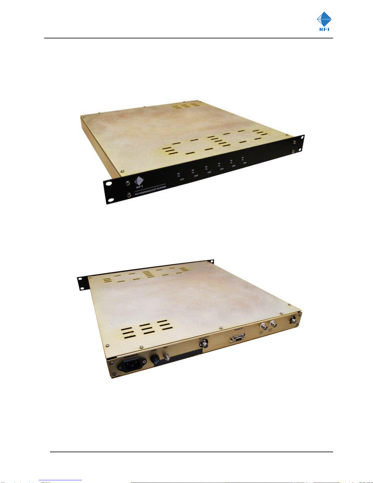
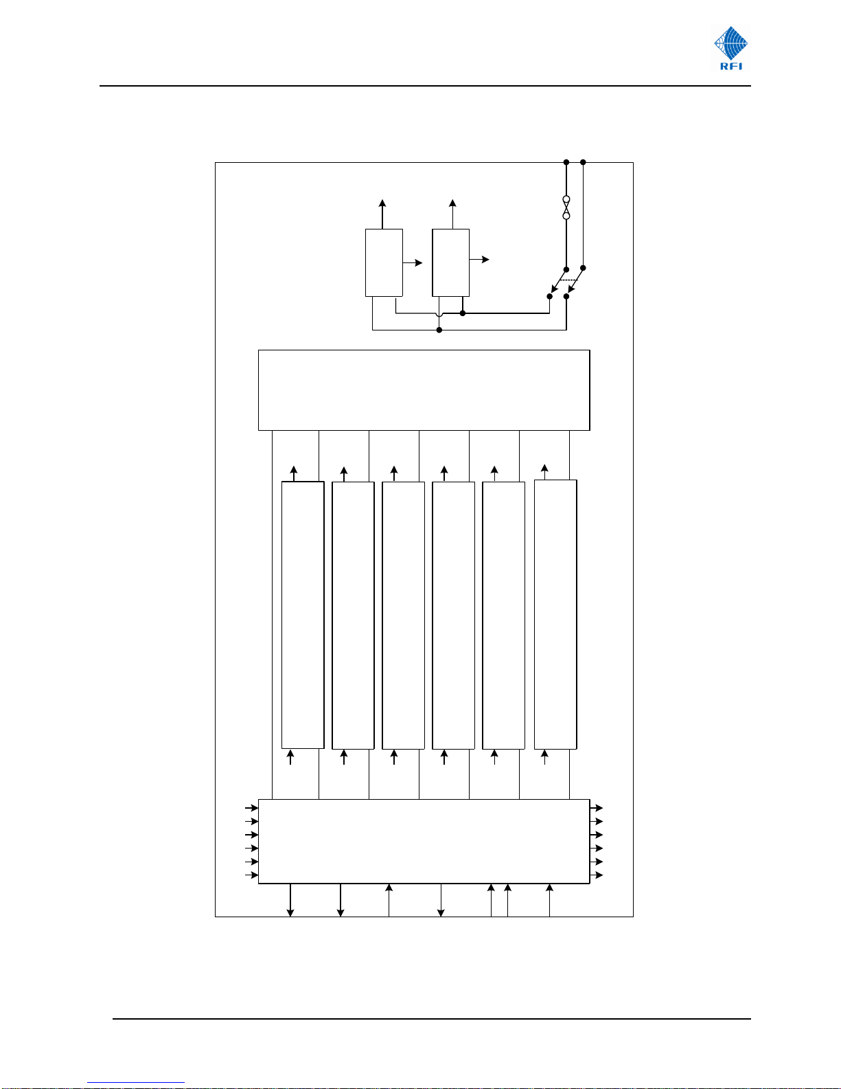
1.1 STRUCTURE....................................................................................................................................................................8
1.2 FRONT AND REAR PANEL LAYOUT.....................................................................................................................................10
2. SPECIFICATIONS ............................................................................................................................................................ 11
3. ORDERING INFORMATION............................................................................................................................................. 12
4. UNPACKING...................................................................................................................................................................12
5. OCCUPATIONAL HEALTH & SAFETY / WORK HEALTH & SAFETY WARNINGS .................................................................. 13
5.1 GENERAL CAUTION........................................................................................................................................................13
5.2 EARTH BONDING ..........................................................................................................................................................13
5.3 HIGH TEMPERATURES ....................................................................................................................................................13
5.4 HIGH VOLTAGE.............................................................................................................................................................14
5.5 ELECTRO STATIC DISCHARGE ...........................................................................................................................................14
6. INSTALLATION ............................................................................................................................................................... 15
6.1 INSTALLATION SUMMARY ...............................................................................................................................................15
6.2 ELECTRICAL CONNECTIONS..............................................................................................................................................15
6.3 POWER ON SEQUENCE ...................................................................................................................................................15
7. OPERATION ................................................................................................................................................................... 16
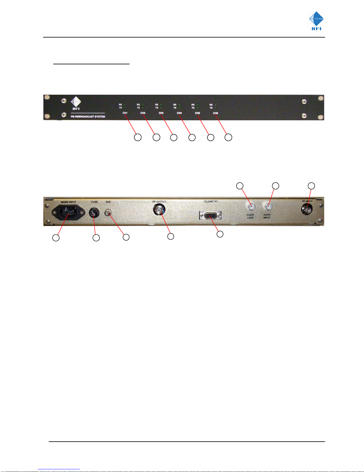
7.1 FRONT AND REAR PANEL CONTROLS AND INDICATORS.(SEE FIGURE 5)...................................................................................16
7.2 TRANSMIT FUNCTION ....................................................................................................................................................17
7.3 RECEIVE FUNCTION .......................................................................................................................................................17
7.4 BREAK IN FACILITY (BIF) ................................................................................................................................................17
8. TECHNICAL DETAILS.......................................................................................................................................................18
8.1 TRANSLATOR PCB ASSEMBLY ..........................................................................................................................................18
8.2 DISTRIBUTION AND DISPLAY PCB ASSEMBLY ......................................................................................................................19
8.3 PSU MODULES ............................................................................................................................................................20
8.4 VHF (87.5 –108MHZ)FREQUENCY REFERENCE TABLES ....................................................................................................21
9. MAINTENANCE, INSPECTION AND REPAIR ADVICE ........................................................................................................ 28
10. USER NOTES: ............................................................................................................................................................... 29

INS-42037-1: FMC88108-6 User’s Manual
Asia Pacific | EMEA | Americas 5
Notice
The information contained in this document is subject to change without notice.
RF Industries Pty. Ltd. makes no warranty of any kind with regard to this material, including but not limited to, the
implied warranties of merchantability and fitness for a particular purpose. RF Industries Pty Ltd shall not be liable
for errors contained herein or for incidental or consequential damages in connection with the furnishing,
performance or use of the material.
All information contained in this manual has been reviewed. However RF Industries Pty Ltd accepts no liability for
any omissions, errors or construed information.
2007-2015, RF Industries Pty Ltd. All rights reserved. Reproduction, adaptation or translation without prior written
permission is prohibited except as allowed under copyright laws.
For further information or help with this product contact your nearest RFI sales office or through the following;

INS-42037-1: FMC88108-6 User’s Manual
Asia Pacific | EMEA | Americas 6
Region
USA
EMEA
ASIA PACIFIC
Sales email
webmaster@rfi.com.au
Tech Support
Telephone Intl
+1 (330) 486 0706
+44 (0) 1869 255772
+61 7 3621 9400
Telephone local
330 486 0706
01869 255772
1300 000 RFI
Fax Intl
+ 1 (330) 486 0705
+61 2 9630 0844
Web
rfiamericas.com
rfiemea.com
rfi.com.au

INS-42037-1: FMC88108-6 User’s Manual
Asia Pacific | EMEA | Americas 7
VHF FM Repeater Translator
Front View
Rear View

INS-42037-1: FMC88108-6 User’s Manual
Asia Pacific | EMEA | Americas 8
1. General Description
This manual contains the technical, installation and operating information for the FMC88108-6 VHF FM
Repeater/Translator. The FMC88108-6 is a cost-effective repeater/translator solution for rebroadcast applications. The unit
can be configured with up to six channels. Additional units can be added into a design to cater for applications that require
more channels.
The FMC88108-6 is a compact unit requiring only 1RU rack space. The unit can be configured to customer requirements
and is primarily used for on-frequency (non-translating) operation, but can also be used in a frequency shifted (translating)
mode of operation if desired.
.
1.1 Structure
The FMC88108-1 VHF FM (87.5MHz to 108MHz) unit comprises the following modules:
a) VHF FM Translator module
b) Display/ Distribution module
c) PSU Modules.
Each translator module performs the function of receiving and transmitting a stereo channel. A BIF (Break In Facility) is
provided for an external audio input be applied for emergency purposes.
The receiver input is filtered by a bandpass response filter, before being divided and amplified via a high level amplifier to
provide six equal outputs which are routed to the six translator modules.
The six transmitter outputs are combined via a six way combiner, providing excellent isolation between RF paths which
reduces intermodulation products.
The resultant RF output is made up of six equal carriers (each internally adjustable) with harmonics and intermodulation
products better than -60dBc.
The block diagram is shown in Figure 1 and the front and rear panel illustrations are shown in Figures 2 and 3 respectively.

INS-42037-1: FMC88108-6 User’s Manual
Asia Pacific | EMEA | Americas 9
Translator PCB
SK1 to Rx
O/P 6
SK3 SK2
SK4 to Tx
I/P 6
Translator PCB
SK1 to Rx
O/P 5
SK3 SK2
SK4 to Tx
I/P 5
Translator PCB
SK1 to Rx
O/P 4
SK3 SK2
SK4 to Tx
I/P 4
Translator PCB
SK1 to Rx
O/P 3
SK3 SK2
SK4 to Tx
I/P 3
Translator PCB
SK1 to Rx
O/P 2
SK3 SK2
SK4 to Tx
I/P 2
Translator PCB
SK1 to Rx
O/P 1
SK3 SK2
SK4 to Tx
I/P 1
66
5
5
4
3
2
1
1
4
3
2
SK13
SK7
SK8
SK9
SK10
SK11
SK12
SK13
SK21
SK20
SK19
SK18
SK17
K16
Front Panel PCB
I/O Board
SK1
SK5
SK6
SK3
SK4
SK2
SK14
65432
1
65432
1
Tx I/P
Rx O/P
PSU #1
L
N
PSU #2
L
N
AC
Switch
Fuse
3.15A
+15Vdc
#1
+15Vdc
#2
AC Mains
N
L
Telemetry
Tx O/P BNC
BIF I/P
BNC
BIF Loop
BNC
+15V #1
+15V #2
Rx I/P BNC
Figure 1: FMC88108-6 Schematic Block Diagram

INS-42037-1: FMC88108-6 User’s Manual
Asia Pacific | EMEA | Americas 10
1.2 Front and Rear Panel Layout
1 2 3 4 5 6
Figure 2: Front Panel
7 8 910 11
12 13 14
Figure 3: Rear Panel
1. Program #1 indicators (Rx and Tx active).
2. Program #2 indicators (Rx and Tx active).
3. Program #3 indicators (Rx and Tx active).
4. Program #4 indicators (Rx and Tx active).
5. Program #5 indicators (Rx and Tx active).
6. Program #6 indicators (Rx and Tx active).
7. A/C Mains input (IEC plug).
8. A/C fuse (1Amp, 20mm type).
9. Ground terminal, M5.
10. RF output connector (50Ohm, BNC female).
11. Telemetry connector (D9 female).
12. BIF audio loop (isolated BNC female).
13. BIF audio input (isolated BNC female).
14. RF input connector (50 Ohm BNC female).

INS-42037-1: FMC88108-6 User’s Manual
Asia Pacific | EMEA | Americas 11
2. Specifications
Note: Tested in non-translating mode of operation
(Tested at 1mV (-47dBm) RF input per channel and 75kHz deviation unless noted)
Electrical
Parameter
Specification
FM modulation type
F3E and F8E (direct carrier)
Frequency range
87.5MHz to 108MHz
Tx output connector
BNC (female) 50 Ohms
Rx input connector
BNC (female) 50 Ohms
Tx output levels per carrier
-15dBm to -4dBm (individually adjustable)
Tx low level alarm
-15dBm nominal
Number of Tx/Rx channels
6 maximum
Tx frequency stability
± 5ppm (other on request)
Tx and Rx synthesizers
50kHz increments
Reference frequency
6.4MHz
FM modulation bandwidth
± 100 kHz nominal
S/N ratio (stereo) with 50µS de-emphasis
≤-60dB (filtered 20Hz –20kHz)
Stereo separation (L into R)
≥45dB (40Hz –15 kHz)
Stereo harmonic distortion
≤0.5% (40 Hz –15 kHz)
Rx static selectivity
≤-85dB @ ± 300kHz nominal
Operational Rx input level per channel
200µV (-61dBm) to 20mV (-21dBm)
Rx low signal alarm
100µV (-67dBm) nominal
Tx non synchronous AM
≤-50dB (20Hz –20kHz)
RF spurious and harmonics
≤-60dBc
Combined Tx intermodulation products
≤-60dBc
BIF (break in facility) level
3V r.m.s. max, balanced (adjustable)
BIF nominal frequency range
30Hz to 8kHz (with pre-emphasis)
BIF audio connectors
Isolated BNC’s (female)
BIF audio deviation per channel
± 68kHz nominal (± 0.5dB)
Translator Physical and Environmental Specifications
Operating Temperature
-10°C to +45°C
Operating altitude
≤2000m
Relative humidity
≤90% non - condensing
A/C mains voltage
100V –240V full range
A/C mains consumption
25VA nominal
A/C frequency
50Hz / 60Hz
Dimensions
485mm x 470mm x 44mm
Weight
3.5 kg
Back Panel Connectors and Functions
RF output
BNC female (50Ω)
Rx input
BNC female (50Ω)
BIF input / output (looped)
Isolated BNC’s female (balanced)
Telemetry (input / output)
D9 female
A/C mains input
IEC plug
A/C fuse
1 Amp 20mm type
Chassis ground
5mm nut / bolt
Telemetry Controls and Alarms (via 9-pin D type female connector)
Pin 1
BIF switching
Apply “Ground”to activate BIF (100mA)
Pins 2 and 3
Ground
Pins 5 and 6
Summary alarm
S/C for fault (LK1 Pos A)
O/C for fault (LK1 Pos B)
Table 1

INS-42037-1: FMC88108-6 User’s Manual
Asia Pacific | EMEA | Americas 12
3. Ordering Information
Ordering Information
RFI Part Number
Description
FMC88108-6
VHF FM Receiver Translator 87.5-108MHz
Table 2
4. Unpacking
The FMC88108 is packed in heavy duty cardboard packaging.
Packed with the unit will be the Factory Test Sheet (FTS). The User’s Manual is available for download from the RFI
website. It is recommended to retain the Factory Test Sheet for future reference.
Although the packaging has been designed to provide suitable product protection during shipping, it is important to report
any visible damage to the carrier immediately.
It is the customers’ responsibility in the event of product damage, to lodge a damage claim with the carrier within a short
period of time after receipt of the package. The time window for lodging the claim should be ascertained from the specific
carrier as this may vary between carriers (typically 1 to 5 days).
Please dispose of all packaging material responsibly.

INS-42037-1: FMC88108-6 User’s Manual
Asia Pacific | EMEA | Americas 13
5. Occupational Health & Safety / Work Health & Safety Warnings
5.1 General Caution
Only a suitably qualified person should be allowed to install and commission this equipment after
comprehending and becoming familiar with all the safety and installation instructions contained in this User’s
Manual. It will be assumed that a qualified person will have a fundamental knowledge of the objectives and
use common sense where safety warnings are not necessarily explicit.
On unpacking the equipment, familiarise yourself with it and read and follow any and all warning labels. Please ensure that
any warning labels are kept in a legible condition and replace if necessary.
Ensure all general, regional and site-specific installation and safety regulations are adhered to when working on high voltage
installations, as well as regulations covering use of tools and personal protective equipment.
It is the responsibility of the network operator or service provider to have in place and implemented a legally compliant
Occupational Health and Safety (OHS) / Work Health and Safety (WHS) law as applicable, detailing prevention measures to
avoid health hazards which may be associated with radiation from the antenna(s) connected to this equipment. Please ensure
familiarisation and compliance to country specific regulations on RF exposure.
Ensure all adjustable repeater settings comply with intended use and applicable National, State and Regional regulatory
requirements.
Please note that only the authorised licence holder for the respective frequencies or frequency range is allowed to operate this
equipment.
Ensure that access to this equipment is restricted to qualified personnel only.
There is no On/Off switch on the unit –it becomes active as soon as AC or DC power is connected via the provided AC mains
cable or DC power source.
Do not allow the FMC88108-6 or any associated equipment to become wet or to be subjected to a corrosive environment,
humidity or temperatures outside the specified operating ranges.
Do not operate the unit near any flammable substances or in a flammable atmosphere.
Ensure that all RF termination connectors are fully mated and hand tightened.
Use this equipment only for the purpose specified by RF Industries Pty Ltd. Do not carry out any modifications or attempt any
repairs. The FMC88108-6 is not intended to be field repairable and should be returned to RF Industries for service or repair.
5.2 Earth Bonding
An equipment earthing / grounding M5 threaded stud is provided at the rear of the enclosure located on the rear
panel (refer Figure 3, #9)
The FMC88108 must be adequately bonded to the common 19” rack earth/grounding connection point within
the 19” rack frame/cabinet using the M5 stud provided.
5.3 High Temperatures
Owing to possible power dissipation within the equipment, the exposed rear portion of the equipment may
reach relatively high temperatures. Please take the necessary precautions when servicing or removing the
equipment.
Please allow adequate ventilation space around the unit when installing this equipment.

INS-42037-1: FMC88108-6 User’s Manual
Asia Pacific | EMEA | Americas 14
5.4 High Voltage
When operated from an AC power source this unit complies with the Australian AS/NZS 60950
equipment safety standard.
There is no surge protection built into the PSU of the FMC88108-6, so additional site specific lighting
protection, voltage surge protection and earth bonding is recommended to reduce the risk of damage.
Regarding external antennas connected to the FMC88108-6, we recommend the use of adequate coaxial lighting protection
and earth bonding through grounding kits on the RF feeder cables prior to termination into the respective RF termination
connectors on the FMC88108-6.
AC or DC mains should also be afforded surge protection.
5.5 Electro Static Discharge
Although exposure of the interconnect sockets / pins has been designed to significantly reduce the risk of
electro static discharge (ESD), precautions must be observed during installation and maintenance to protect
all the modules within the equipment.

INS-42037-1: FMC88108-6 User’s Manual
Asia Pacific | EMEA | Americas 15
6. Installation
The FMC88108-6 is designed to be installed into standard 19” rack mount frames or cabinet spaces and is intended for indoor
use only.
Power connection to the unit must be made via the rear IEC connector with the required power capacity. The equipment must
only be used with a properly earthed mains supply
Adequate provisions must be made to ensure that the air flow is not impeded at either the front or the rear of the unit. Under
no circumstances should the unit be allowed to become wet.
Ensure that the power source is disconnected before removal of any covers.
6.1 Installation Summary
Lightning protection, grounding, and the appropriate torqueing of connectors and the sealing of terminations are all important
facets of any system installation. Careful attention should be given to these areas
The type of coaxial feeder cables that may be used with the FMC88108-6 may vary, but generally their type will be determined
by their length (and resulting insertion loss) and associated jumper/ tail requirements.
Always follow engineering best practices for equipment installation.
Note: The operating frequencies will normally be set at factory configuration, but if different operating frequencies are
necessary then the unit top cover has to be removed and the new frequencies selected on the translator modules. This is
done by setting the DIP switches as detailed in table 3 (refer pages 31-37) and by following the operation details in Section 7.
6.2 Electrical Connections
A/C mains supply (100V - 240V): Connect A/C power cable to IEC connector on rear panel.
Receiver RF input (BNC): Connect RF input cable to the Rx input on the rear panel.
Transmitter RF output (BNC): Connect the RF output cable to the RF output on the rear panel.
Note: When the telemetry connector is not in use the unit requires no external commands to enable RF
6.3 Power on Sequence
Connect the unit by plugging in the mains power cable.
The front panel channel LEDs (green) should be illuminated after approximately 10 seconds.
(This only applies to the number of translator modules fitted).
Rx LED’s will be off if the incoming receive signal is too low or the Rx synthesizer is either “out of lock”or set to an
incorrect frequency.
Tx LED’s will be off if the RF output is too low or the Tx synthesizer is “out of lock.”
Note: If a translator module is not fitted, then that particular pair of channel LED’s will be off.

INS-42037-1: FMC88108-6 User’s Manual
Asia Pacific | EMEA | Americas 16
7. Operation
Note:
It is recommended that the users familiarize themselves with the operating controls and connectors before using the
equipment.
1 2 3 4 5 6
Figure 4: Front Panel Layout
7 8 910 11
12 13 14
Figure 5: Rear Panel Layout
7.1 Front and Rear Panel Controls and Indicators. (See Figure 5)
1. Channel #1 indicators (Rx and Tx active).
2. Channel #2 indicators (Rx and Tx active).
3. Channel #3 indicators (Rx and Tx active).
4. Channel #4 indicators (Rx and Tx active).
5. Channel #5 indicators (Rx and Tx active).
6. Channel #6 indicators (Rx and Tx active).
7. A/C Mains input (IEC plug).
8. A/C fuse: 1 Amp, 20mm type.
9. Ground terminal, M5.
10. RF output connector (50 Ohm, BNC female)
11. Telemetry connector (D9 female).
12. BIF audio loop (isolated BNC female).
13. BIF audio input (isolated BNC female).
14. RF input connector (50 Ohm BNC female).

INS-42037-1: FMC88108-6 User’s Manual
Asia Pacific | EMEA | Americas 17
7.2 Transmit Function
The FMC88108-6 Repeater Translator is primarily used for receiving (normally from a single antenna) and then re-
broadcasting up to six separate VHF FM carriers (individually adjustable via R97 on each translator module)
The receive and transmit frequencies are selected via the DIP switches SW1 (Receive) and SW2 (Transmit) on each
translator module. The receiver and transmitter will normally be set to the same operating frequency, but alternative
frequencies can be used if so required by the end user. Frequency programming tables are provided in section 5 of this
manual for this purpose. Green LED indicators D8 and D9 are provided on each translator module for indication of Rx and Tx
synthesizer lock.
Each translator module has a potentiometer R97 (RF level adjust) to set the RF output level. These levels are normally set
using a spectrum analyser, displaying all carriers simultaneously.
7.3 Receive Function
Each translator module is equipped with a tunable RF channel filter which must be fine tuned to the desired frequency. Coarse
tuning is done automatically via varactor diodes and fine tuning is done by simply adjusting inductors L1 and L2. These will
normally be set at the factory but can also be adjusted by the end user. To tune the filter, monitor the DC voltage at IC7, pin
13 with a digital Volt meter and adjust L1 and L2 to achieve the maximum positive voltage. This can be done either with an off-
air signal or with an RF signal generator.
No other adjustments are normally required on the receiver section as these will be preset at the factory.
7.4 Break In Facility (BIF)
When an emergency audio broadcast is required to all six FM channels, the audio source is input to one of the isolated BIF
inputs (BNC’s) on the rear panel. No pre-emphasis is required for this purpose as it is already tailored for speech within the
FMC88108-6. The BIF audio feed can be activated by grounding pin 1 (100mA sink) on the telemetry D9 connector. (Ground
is available on pins 2 and 3)
The BIF deviation levels for all carriers can be adjusted via a single potentiometer R13 on the display/distribution module. This
is normally set to provide ± 68 kHz deviation with a 500Hz tone.
A summary alarm is also available on the telemetry connector on pins 6 and 7. This output contact is voltage free and can be
set for s/c or o/c contact via LK1 (on the display/distribution module)
The summary alarm will be activated should any of the receivers lose signal strength (below 100µV) or any of the transmitters
have loss of output level (below -15dBm)
Green LED indicators are provided on the front panel to allow visual indication of Rx and Tx status. LEDs will be illuminated
when conditions are normal. If a translator module is removed the LEDs for that particular module will be off.
NOTE: if the end user decides to only use a lesser number of modules than the six fitted, then the jumper links (for the
summary alarm) for those particular modules should be removed, otherwise the summary alarm will be activated.
These links are situated on the front panel display/distribution PCB:
Module 1………………………….LK2 and LK3
Module 2………………………….LK4 and LK5
Module 3………………………….LK6 and LK7
Module 4………………………….LK8 and LK9
Module 5………………………….LK10 and LK11
Module 6………………………….LK12 and LK12
The unused modules should be disconnected at SK3 on the display/distribution PCB so that their Tx carrier is removed.

INS-42037-1: FMC88108-6 User’s Manual
Asia Pacific | EMEA | Americas 18
8. Technical Details
8.1 Translator PCB Assembly
a) Band Pass Filter, Mixer and 10.7MHz IF Filter.
The VHF (87.5 –108MHz) RF input is routed from SK1 to a bandpass filter which is tuned using varactor diodes D1
and D2. L1 and L2 can be used for fine tuning. The tuning voltage for the varactor diodes is derived from the local
oscillator locking voltage at IC2/B pin 7 and can be monitored at TP1.
The output of the bandpass filter is routed to the mixer (MX1). The mixer is a passive double balanced type with a local
oscillator drive level of -76dBm from IC3. The output of the mixer is routed to a 10.7MHz IF bandpass filter.
The 10.7MHz bandpass filter consists of three ceramic filters (FL1, FL2 and FL3) that have low group delay and
excellent attenuation characteristics. Each filter has tuning capacitors at the input side (C10, C15 and C20) to obtain
optimum stereo distortion and separation characteristics. Each filter is buffered by a J-Fet high impedance amplification
stage to recover the insertion loss of the individual filters (approximately 6dB). The filters are terminated with optimum,
220 Ohms resistive loads. The complete filter gives attenuation of approximately 20dB at ± 200kHz offset and 60dB at
± 300kHz offset. Spurious response is better than 75dB. The high Q of the ceramic filters ensures excellent
performance and stability compared to normal LC filters.
b) Rx Frequency Synthesizer with Local Oscillator.
The Rx synthesizer consists of a single loop with a divide by 65 pre-scaler IC4. A 6.4MHz reference crystal is utilized
with a parallel loaded synthesizer chip IC5. This reference is divided internally by 8192 to 781.25Hz. This mode of
operation provides frequency steps of 50kHz via the 12 way DIP switch SW1. (64 x 781.25Hz = 50kHz). The LD output
on IC5 provides a lock detect function and is routed to IC13/A. LED D8 provides the Rx lock function indication.
The local oscillator (TR5 and buffer amplifier IC3) is routed via the pre-scaler (IC4) to the programmable divider in the
synthesizer (IC5), whose division ratio is set by DIP switch (SW1). The DIP switches set the local oscillator frequency
between 76.8MHz and 97.3MHz, which is 10.7MHz lower than the required receive frequency (87.5MHz - 108MHz).
The local oscillator output from IC3 is also routed to mixer MX1.
The phase comparator output of IC5 (PD-OUT) has a 3-state output and is applied to a loop integrator and loop filter
(IC2), whose DC output in turn controls the frequency of the local oscillator via varactor diode D4. (Control sensitivity is
approximately 2MHz/Volt). A +5V regulator IC6 is provided for the Rx and Tx synthesizers.
c) IF Demodulator (10.7MHz).
The 10.7MHz input is routed to pin 15 of IC7. The 10.7MHz IF demodulator is a simple, single tuned quadrature type
(IC7). The balanced output of the demodulator at pins 8 and 9 contains the demodulated baseband signal. This
provides common mode rejection and good S/N ratio, typically ≥70dB. C61 is provided to optimally tune the
demodulator for minimum second harmonic distortion. A DC voltage proportional to the field strength is provided on pin
13 of IC7 and is adjusted via R41. This output is routed to comparator IC16/B and the switched DC output can be
monitored at SK2 pin 1. The balanced baseband output from the demodulator is routed to the signal processing circuits.
d) Baseband Amplitude and Phase Correction with 100kHz Low Pass Filter.
The baseband signal from the IF modulator is routed to a balanced unity gain amplifier stage (IC8/A). This is then
routed to a low pass filter stage (IC8/B) in conjunction with a band reject filter (IC9/B). This stage also provides the
amplitude correction for the IF filter and is adjusted via R53 to achieve maximum stereo separation at 1kHz. A group
delay correction circuit (IC9/A) is also provided for optimal stereo separation at 15kHz and is adjusted via R58.
The baseband output from IC9/A is routed via R62 (Rx baseband level adjust) to RL1/A and RL1/B for audio switching
purposes. Relay RL1/C is switched via SK3 pin 1 (s/c to ground) and this allows the Rx baseband to be switched off
and allow the BIF input, on SK3 pin 4, to be activated (to accept an external audio input). These signals are then routed
to the Tx modulator circuits.

INS-42037-1: FMC88108-6 User’s Manual
Asia Pacific | EMEA | Americas 19
e) Synthesizer and Loop Filter (87.5MHz –108MHz).
The synthesizer consists of a single loop with a divide by 64 pre-scaler IC14. Direct carrier modulation is used in this
application. The 6.4MHz crystal circuit provides the reference for the synthesizer IC10. The reference is then divided by
8192 by IC10 to 781.25Hz. This mode of operation provides frequency steps of 50kHz via the 12 way DIP switch SW2
(64 x 781.25Hz = 50kHz). The DIP switches set the oscillator frequency (87.5MHz –108MHz). The LD output on IC10
provides a lock detect function and is routed to IC13/B and LED indicator D9.
The phase comparator output of IC10 (PD-OUT) has a 3-state output and is applied to a loop integrator (IC11) and loop
filter (IC12) whose DC output in turn controls the frequency of the oscillator (VCO).
f) VCO and Modulation Inputs.
The modulation inputs from figure 9 via RL1 are routed to varactor diodes D13 and D14. These provide the modulation
within the Fet oscillator TR6. Varactor diodes D11 and D12 control the tuning of the modulator/ oscillator TR6 via the
loop filter. The modulator has a built in DC correction circuit to keep the modulation constant over the frequency range
87.5MHz to 108MHz.
The output of TR6 is routed to the 64 pre-scaler IC14. The output of TR6 is also routed to buffer IC15 which provides up
to +10dBm RF output. The current in the IC is controlled via R97 which reduces the level of its output. This
potentiometer (R97) is therefore used to set the output level required during use. TR7 is provided to ensure that if the Tx
synthesizer is out of lock the output will be switched off.
The RF output from IC15 is routed to a 6dB splitter whose outputs are routed to diode detection circuit D15 and IC16/A
(to detect loss of carrier) and also a low pass filter to remove harmonics from the carrier. The output is then routed to RF
connector SK4.
8.2 Distribution and Display PCB Assembly
a) PSU and BIF Audio.
The BIF (Break In Facility) audio (nominally +10dBm) is input at SK3 or SK4 to a balanced line circuit IC1/B. DC
blocking capacitors C1 and C2 are provided to ensure no DC component enters the circuit. Capacitors C3 and C4 are
provided to ensure that no RF signals can enter the circuit, which would cause audio distortion. The output of IC1/B is
routed to IC1/A which forms an 8kHz low pass filter with added pre-emphasis lift for optimum voice equalization. This
means that no pre-emphasis would be required at the audio source. R13 is provided to allow level adjustment on all six
translator modules to achieve approximately 68kHz deviation (nominal) on all six transmitters at the same time. The BIF
signal is distributed to all six connectors SK7 to SK12 for this purpose on pin 4.
The +15V DC PSU inputs on SK5 and SK6 are routed to fuses F1 and F2 respectively for protection purposes. These
two supplies are then distributed to SK7, SK8, SK9 (+15V #1 supply) and SK10, SK11 and SK12 (+15V #2 supply).
The two supplies are also combined via diodes D1 and D2 to power all other circuits on this module.
b) RF Amplifier with 6 Way Splitter and Output Combiner.
RF Input Section
The RF input at SK1 (BNC) is routed to a wide bandpass filter that passes the entire VHF FM band from 87.5MHz to
108MHz. This filter is provided to attenuate signals out of band from entering the RF amplifier stage IC2. The RF
amplifier stage IC2 is operated at 80 mA and has a high 1dB compression point of +19dBm. The amplifier has a power
gain of 25dB
The output of the amplifier IC2 is routed to a 6 way splitter (IC3) which provides six equal outputs for the six translator
modules. The splitter provides excellent isolation of ≥28dB between each output port. The total conversion gain of this
RF section is typically +17dB.
RF Output Section
The RF inputs from the six translator modules at TP7 and TP12 are routed to a 6 way combiner (IC4) which provides a
single output. Loss in the combiner is typically 8dB. The combiner provides excellent isolation of ≥28dB between each
input port, thus keeping intermodulation products to an absolute minimum. The output of the combiner is routed to a
wide bandpass filter that passes the entire VHF FM band from 87.5MHz to 108MHz. This is then routed to SK2 (RF
output).

INS-42037-1: FMC88108-6 User’s Manual
Asia Pacific | EMEA | Americas 20
c) Distribution.
SK7, SK8 and SK9 provide the following pin outs:
1. BIF switching command to translators.
2. +15V #1 supply
3. 0V Ground
4. BIF audio output to translators.
SK10, SK11 and SK12 provide the following pin outs:
1. BIF switching command to translators.
2. +15V #2 supply
3. 0V Ground
4. BIF audio output to translators.
SK13 provides the input from the display module that activates the summary alarm relay RL1/C via TR1.
SK14 (D9 female) provides a summary alarm contact via RL1/A. The voltage free contact is output on pins 6 and 7.
LK1 is provided for s/c or o/c contact.
SK14 pin 1 provides the activation (s/c to round) for the BIF audio switching.
Ground connections are provided on pins 2 and 3 (SK14).
8.3 PSU Modules
Note: Two of these modules are used in the FMC88108-6
The switching power supply converts the A/C supply to a voltage of +15V nominal. The supply includes over-current, over-
temperature and over-voltage protection. The supply can generate 1A @ 15V and is conservatively rated for use in this
application.
Specifications:
AC Input………………………………………………………………………..Full range 85V to 240V (50/60Hz)
DC output………………………………………………………………………+15V (adjustable ±10%)
Efficiency……………………………………………………………………….≥81%
Operating temperature………………………………………………………..-20°C to +60°C
EMC standards………………………………………………………………...EN55022, EN61000, ENV50204
Table of contents