RFL Electronics 9831 Installation and user guide

RFL Electronics Inc RFL 9831
(973) 334-3100 1 March 8, 2004
RFL Electronics Inc
I N S T R U C T I O N D A T A
RFL 9831 Dual Path Programmable Modem
DESCRIPTION
The 9831 Dual Path Modem is a high performance module suitable for applications on 2-wire or 4-
wire pilot cable systems. It is capable of throughput speeds of up to 9600 baud using v.29 full duplex
communication over a 4-wire pilot cable system.
0
5
1
4
2
3
9
6
8
7
9831
Power
TXD
CTS
RXD
DCD
Mode
Select
CFG
1 2
RFL 9831 MOD
105270
Because RFL™ and Hubbell® have a policy of continuous product improvement, we reserve the right to change designs and specifications without notice.

RFL Electronics Inc RFL 9831
(973) 334-3100 2 March 8, 2004
Table of Contents
1. INTRODUCTION............................................................................................................................................................3
1.1. TERMINOLOGY USED IN THIS MANUAL......................................................................................................................3
2. GENERAL .......................................................................................................................................................................4
3. TECHNICAL DESCRIPTION ........................................................................................................................................5
3.1. MECHANICAL DIMENSIONS AND MOUNTING.............................................................................................................5
3.2. THE MODEM CARD.................................................................................................................................................5
3.2.1. Power Supply ...................................................................................................................................................5
3.2.2. Directional Control Logic.................................................................................................................................6
3.2.3. LED Indications ...............................................................................................................................................6
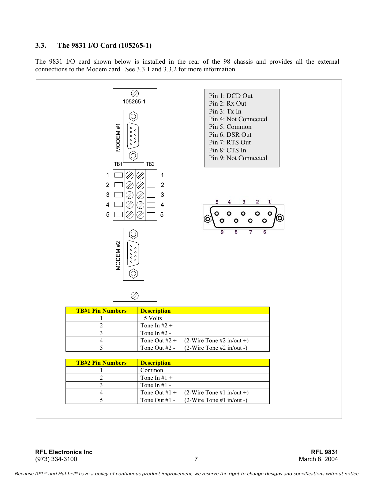
3.3. BACK 9831 I/O CARD ................................................................................................................................................7
3.3.1. Serial Communication Ports.............................................................................................................................8
3.3.2. 4-Wire Line and Power Connectors .................................................................................................................8
3.4. MODEM CARD...........................................................................................................................................................9
3.4.1. Microprocessor and Support Logic ..................................................................................................................9
3.4.2. Transmit and Receive DSP Data Pumps ........................................................................................................10
3.4.3. Analogue Line Circuitry.................................................................................................................................10
3.4.4. Isolating Line Transformers ...........................................................................................................................10
4. MODE SELECTION .....................................................................................................................................................11
4.1. COMMUNICATION MODES .......................................................................................................................................11
4.1.1. Switched or Constant Carrier .........................................................................................................................11
4.1.2. DCD Framing .................................................................................................................................................12
4.1.3. Anti-Collision Provision.................................................................................................................................12
4.2. CONNECTION MODES ..............................................................................................................................................13
4.2.1. Configuration Mode .......................................................................................................................................13
4.2.2. Point to Point Mode (P-P) ..............................................................................................................................14
4.2.3. Multi-drop Master / Slave (M/S)....................................................................................................................14
4.2.4. Redundant Loop (LOOP) ...............................................................................................................................15
4.2.5. Redundant Point to Point................................................................................................................................17
5. CONFIGURATION GUIDE ..........................................................................................................................................18
5.1. JUMPER AND SWITCH CONFIGURATION ..............................................................................................................18
5.1.1. Jumper Configuration.....................................................................................................................................18
5.1.2. Switch Configuration .....................................................................................................................................18
5.2. SOFTWARE CONFIGURATION ...................................................................................................................................19
5.2.1. Overview ........................................................................................................................................................19
5.2.2. Quick Start......................................................................................................................................................20
5.2.3. Main Form Fields ...........................................................................................................................................21
5.2.4. Main Form Buttons ........................................................................................................................................24
5.2.5. Load From File...............................................................................................................................................26
5.2.6. Save To File....................................................................................................................................................26
5.2.7. Upload From Device ......................................................................................................................................26
5.2.8. Download To Device......................................................................................................................................27
5.2.9. Communication Settings ................................................................................................................................27
5.2.10. Errors..............................................................................................................................................................28
6. TROUBLESHOOTING..................................................................................................................................................29
6.1. MODEM PROBLEMS .................................................................................................................................................29
6.2. CONNECTION MODE PROBLEMS ..............................................................................................................................31
Because RFL™ and Hubbell® have a policy of continuous product improvement, we reserve the right to change designs and specifications without notice.

RFL Electronics Inc RFL 9831
(973) 334-3100 3 March 8, 2004
1. Introduction
This manual describes the features of the 9831 Dual Path/Redundant Modem and shows the user how to install
and configure the unit for correct operation. This manual is intended for the use of technical personnel
undertaking technical related engineering tasks such as installation, maintenance and configuration.
1.1. Terminology used in this Manual
RTU Remote Terminal Unit
RS232 EIA recommended interface for serial data communication
LED Light Emitting Diode
CPU Central Processing Unit
DTE Data Terminal Equipment
DCE Data Communication Equipment
RTS Request to Send
CTS Clear to Send
DCD Data Carrier Detect
DSR Data Set Ready
DTR Data Terminal Ready
TXD Transmit Data from DTE
RXD Receive Data from DCE
DSP Digital Signal Processor
Because RFL™ and Hubbell® have a policy of continuous product improvement, we reserve the right to change designs and specifications without notice.

RFL Electronics Inc RFL 9831
(973) 334-3100 4 March 8, 2004
2. GENERAL
The 9831 Dual Path Modem is a high performance module suitable for applications on 2-wire or 4-wire pilot
cable systems.
The modem module is capable of throughput speeds of up to 9600 baud using V.29 full duplex communication
over a 4-wire pilot cable system. The modem is also compatible with older communication standards such as
V.23 and Bell 202. It only needs to be reconfigured for higher baud rates.
Each modem module contains up to two individual modems for providing the dual path capability. The 9831
modem along with the 9831 I/O module installs in any of the various available standard 98 Series chassis. All
external connections are made to the 9831 I/O module installed at the rear of the 98 chassis.
For system diagnostics, there are LED indications for the status of the link.
Product Highlights
• Installs in any 98 Series Chassis
• LED indication for all data signals
• Front panel modem configuration port
• Two RS 232 serial communication ports
• V.29 9600 baud throughput
• V.23, Bell 202 compatible
• V.22bis 2400 baud throughput
• Point to point, redundant path or master/slave polling operation
• Compression type disconnect terminal for power connections on 9831 I/O
• Compression type disconnect terminals for analog communication lines on 9831 I/O
Because RFL™ and Hubbell® have a policy of continuous product improvement, we reserve the right to change designs and specifications without notice.

RFL Electronics Inc RFL 9831
(973) 334-3100 5 March 8, 2004
3. Technical Description
This section describes all technical features of the 9831 Modem in detail and also explains the mounting of the
unit.
3.1. Mechanical Dimensions and Mounting
The 9831 Modem is made up of three different types of cards.
• Modem Card (RFL Part Number 105270)
• Second optional plug-on Modem Board (RFL Part Number 105280)
• Back Connection 9831 I/O Card (RFL Part Number 106140-1)
The 9831 Modem card is contained on a 3RU board, with a front panel width of 1 inch. This card can be
mounted in any standard 98 Series chassis.
The plug-on second Modem Board (if supplied) installs as a daughter board onto the Modem card.
The 9831 I/O card installs in the rear of the 98 Chassis and mates with the 9831 Modem card. All external
connections are made to this 9831 I/O card.
3.2. The 9831 Modem Card (105270)
The modem card accommodates the primary modem, all the LED indications and the directional control logic.
It has accommodations for an optional second modem installed as a plug-on daughter board to the modem card
itself.
3.2.1. Power Supply
The +5 VDC required by the modem card is provided by the 98 Power Supply module installed in the chassis.
This voltage is wired to the modem via the 9831 I/O module (refer to section 3.3.2). The various 98 Power
Supplies available are 24, 48, 125 or 250 VDC and 120 or 220 VAC.
The power supply circuitry on the modem module converts the +5VDC input to the required
–5VDC for the analog circuitry. This function is provided with the use of a small DC/DC Inverter.
The current requirement for the +5 VDC is 300ma.
Because RFL™ and Hubbell® have a policy of continuous product improvement, we reserve the right to change designs and specifications without notice.

RFL Electronics Inc RFL 9831
(973) 334-3100 6 March 8, 2004
3.2.2. Directional Control Logic
A redundancy function is provided through directional control logic on the RS-232 ports and 4-wire line. The
control logic depends on the connection mode selected. The connection mode is provided using the BCD rotary
switch.
The connection logic determines the configuration of the following signals:
• Serial RxD
• Serial DCD
• Serial CTS
• Modem 1 Transmit
• Modem 2 Transmit
The details of the control logic are discussed in section 4 on page 11.
3.2.3. LED Indications
The modem card provides multiple LED indications for each of the supplied modems. If the optional second
modem daughter board is not installed, the LEDs for this modem will not be illuminated.
The LED indications for each modem are:
• Green Power LED
• Red Transmit Data (TxD) LED
• Red Clear To Send (CTS) LED
• Red Receive Data (RxD) LED
• Red Data Carrier Detect (DCD) LED
Depending on the current mode of operation, the CTS and DCD LEDs may have varying functions. For more
details on the RTS and DCD modes, please refer to sections 4.1.1 and 4.1.2.
Because RFL™ and Hubbell® have a policy of continuous product improvement, we reserve the right to change designs and specifications without notice.

RFL Electronics Inc RFL 9831
(973) 334-3100 7 March 8, 2004
3.3. The 9831 I/O Card (105265-1)
The 9831 I/O card shown below is installed in the rear of the 98 chassis and provides all the external
connections to the Modem card. See 3.3.1 and 3.3.2 for more information.
TB#1 Pin Numbers Description
1 +5 Volts
2 Tone In #2 +
3 Tone In #2 -
4 Tone Out #2 + (2-Wire Tone #2 in/out +)
5 Tone Out #2 - (2-Wire Tone #2 in/out -)
TB#2 Pin Numbers Description
1 Common
2 Tone In #1 +
3 Tone In #1 -
4 Tone Out #1 + (2-Wire Tone #1 in/out +)
5 Tone Out #1 - (2-Wire Tone #1 in/out -)
Pin 1: DCD Out
Pin 2: Rx Out
Pin 3: Tx In
Pin 4: Not Connected
Pin 5: Common
Pin 6: DSR Out
Pin 7: RTS Out
Pin 8: CTS In
Pin 9: Not Connected
MODEM #2 MODEM #1
105265-1
TB1 TB2
1 1
2 2
3 3
4 4
5 5
Because RFL™ and Hubbell® have a policy of continuous product improvement, we reserve the right to change designs and specifications without notice.

RFL Electronics Inc RFL 9831
(973) 334-3100 8 March 8, 2004
3.3.1 Serial Communication Ports
The upstream modem is primary modem supplied on the modem card and is connected to the MODEM #1 port
on the 9831 I/O card. The downstream modem is the optional plug-on daughter board and is connected to the
MODEM #2 port on the 9831 I/O card.
Both communication ports MODEM #1 and MODEM #2 are fully compliant with RS232/V.24 and V.28
standards for Data Communication Equipment (DCE). The sockets are 9 pin D-Type female with threaded
studs.
The pin-out for the DB-9 female connectors is shown in the figure in section 3.3.
3.3.2. 4-Wire Line and Input Power Supply Connectors
There are two 5-pin compression type terminal connections for the 4-wire line and power supply connections.
Eight of the ten connections are for the 4-wire lines. This is because the modem module can have up to two 4-
wire connections. These can be one for up-stream and one for down-stream, or one for main path and one for
redundant path.
Two of the ten connections are for the +5 volt power supply input wired from the 98 Power Supply I/O module.
The pin-out for the two 5-pin connectors is shown in section 3.3.
Because RFL™ and Hubbell® have a policy of continuous product improvement, we reserve the right to change designs and specifications without notice.

RFL Electronics Inc RFL 9831
(973) 334-3100 9 March 8, 2004
3.4. Modem Card
The modem card provides a single channel of 2-wire or 4-wire communication between itself and another
modem card connected remotely via a 2 or 4-wire connection.
To provide this functionality, the modem card contains the following hardware:
• Microprocessor and Support Logic
• Transmit DSP Data Pump
• Receive DSP Data Pump
• Analog Line Circuitry
• Isolating Line Transformers
Each of these functions is discussed in the following sections.
3.4.1. Microprocessor and Support Logic
The microprocessor and support logic is required to perform the following functions:
• Various Input Baud rates provided
• Formatting of Data Pump transmit and receive data
• Configuration of the Data Pumps for the associated modes
• Intelligence for the different redundancy modes
• Ability to provide store and forward functionality in the system
To provide this functionality, the following hardware is used:
• Atmel 89C8252 Microprocessor
• 128K x 8 Static RAM
• GAL Logic
• Associated buffers
The microprocessor contains 8Kbytes of program FLASH memory and 2Kbytes of data EEPROM for storing
the modem configuration. The FLASH can be programmed in-line, and the EEPROM configuration is
programmed via the configuration utility provided on the PC and downloaded through the serial port.
The 128Kbytes of external SRAM is provided for message buffering and various program variables storage.
Because RFL™ and Hubbell® have a policy of continuous product improvement, we reserve the right to change designs and specifications without notice.

RFL Electronics Inc RFL 9831
(973) 334-3100 10 March 8, 2004
3.4.2. Transmit and Receive DSP Data Pumps
Two DSP Data Pumps are used to perform all analog modem functions. Each of the data pumps can only
provide half-duplex functionality in certain modes, therefore two data pumps are used to provide full duplex
functionality.
The transmitter data pump takes the formatted data from the microprocessor under interrupt control and the
receive data pump provides raw data for the microprocessor to decode, also under interrupt control.
The configuration that is stored in the data EEPROM is passed from the microprocessor to the data pumps
whenever a mode change is experienced. The configuration is also downloaded to the data pumps on system
startup.
3.4.3. Analog Line Circuitry
The analog line circuitry is required to convert the output signal from the transmitter data pump into valid line
levels for transmission through the isolating line transformer. It also translates the receiver input line signal into
a level and format that the receiving data pump can handle. This circuitry is handled by some Operational
Amplifiers and some passive components to set the levels correctly.
This section also provides the line impedance. The two settings available are 600 ohms and 10K ohms for both
transmit and receive line impedance. The configuration of these parameters is detailed in section 5.1.
3.4.4. Isolating Line Transformers
The line isolating transformers are required on both transmit and receive sides in order to isolate the modem
card from the line. These transformers are 1:1 and provide the two selectable line impedances of 600 ohms and
10K ohms.
Because RFL™ and Hubbell® have a policy of continuous product improvement, we reserve the right to change designs and specifications without notice.

RFL Electronics Inc RFL 9831
(973) 334-3100 11 March 8, 2004
4. Mode Selection
The 9831 modem is not just a standard modem that is connected at each end of a 4-wire communication line.
This modem can communicate in a number of different configurations, all of which are discussed in detail in this
section of the manual.
First, the different communication modes supported by the 9831 are discussed, followed by the different
connection modes for connecting multiple 9831 modems together.
4.1. Communication Modes
The following is a list of the communication modes supported by the 9831:
Configuration Modulation Carrier
Freq.
Data
Rate
Full
Duplex
2 or 4
wire
Constant
Carrier
Required
V.29 (9600) QAM 1700 9600 Yes 4 Yes
V.29 (7200 baud) QAM 1700 7200 Yes 4 Yes
V.22bis (2400 baud) QAM 1200/2400 2400 Yes 2 Yes
V.23 (1200 baud) FSK 1300/2100 1200 Yes 4 No
Bell 202 (1200 baud) FSK 1200/2200 1200 Yes 4 No
These communication modes are selected via the software configuration utility as described in section 5.2.
It should be noted that certain communication modes have a delay through each modem link. This delay is
caused by the Trellis Encoding and the Forward Error Correction used in the more complicated encoding
schemes such as V.29. The delay through each of the modems in a V.29 link is approximately 15 milliseconds.
For some of the connection modes, where the message is repeated around the link, this maximum time delay is
incurred through each modem.
4.1.1. Switched or Constant Carrier
As shown in the table above, some communication modes require a constant carrier to be present for the modem
link to work. The reason is that the transmit and receive modem pair must be synchronized for the encoding to
work.
In the case of constant carrier, the RTS line is ignored. The CTS LED indicates the quality of the link. If the
CTS LED is ON, then the link is running. If the CTS LED is not on then the link is not running correctly.
For the communication modes that support switched carrier, the CTS LED becomes a mirror of the RTS line,
although with a short ON delay.
Because RFL™ and Hubbell® have a policy of continuous product improvement, we reserve the right to change designs and specifications without notice.

RFL Electronics Inc RFL 9831
(973) 334-3100 12 March 8, 2004
4.1.2. DCD Framing
For the communication modes that support switched carrier, the DCD LED indicates when the carrier is being
received by the modem. If constant carrier mode is selected (or required, depending on the communication
mode) the DCD signal (and LED) can be made to stay ON or to be framed around incoming messages.
If the DCD LED and signal are configured to be framed around incoming messages, it will remain inactive until
data is received. Once this data is received, the DCD line will become active and will stay active while data is
being received, until there is no receive data for the DCD OFF Delay timeout. This value is set in the
configuration tool.
4.1.3. Anti-Collision Provision
In the redundant loop mode (explained in the following chapter), the modem provides an anti-collision provision
that will try to avoid collisions of data going around the loop with input serial data from the serial port on the
modem.
This anti-collision has to be co-operative. Each 9831 modem card contains two modems and one input serial
port (in redundant loop mode). Each modem can not tell where the data is coming from, either the input serial
port or the other modem. Because of this it is not possible to provide a true store and forward capability as the
modem card can not determine the input serial source as both the inputs from the serial port and the other
modem are combined on the modem card.
When the modem receives serial input data, it notifies the other modem that it is receiving serial data. If the
other modem is not sending out serial data, it knows that there must be serial data coming from the input serial
port. For this duration, it will accumulate any incoming data on the modem line and will delay it until the other
modem indicates that it is no longer receiving data. It will then start transmitting the data to the other modem
for forwarding.
Conversely, the input serial device must NOT send serial data if the other modem is currently transmitting serial
data to the modem card. This can ONLY be achieved by the use of the DCD line on the serial port. Also, the
DCD framing must be used. Therefore, while DCD is active, the serial device must not send any data. When
DCD becomes inactive, the serial device may again send data.
The timeouts used for this provision are the DCD OFF delay explained in another section of this manual.
Because RFL™ and Hubbell® have a policy of continuous product improvement, we reserve the right to change designs and specifications without notice.

RFL Electronics Inc RFL 9831
(973) 334-3100 13 March 8, 2004
4.2. Connection Modes
The connection mode required is determined by the BCD rotary switch on the front of the 9831 Modem card.
The various modes of operation are shown below:
• Configuration Mode
• Point to Point
• Multi-drop Master / Slave
• Redundant Loop
• Redundant Point to Point
Each of these different modes requires different configurations and options. These are explained in detail in the
following sections.
4.2.1. Configuration Mode
The configuration mode allows the downloading and uploading of configuration information of each of the
modems on a modem card. This is supported via the CFG serial port connection on the front panel of the 9831
modem card. The CFG port is a standard 9-pin D-type female connector. Once the modem card is switched
into configuration mode, the serial port is hard coded into a defined set of parameters for communication with
the PC-based 9831 Configuration Utility.
When the modem is switched into configuration mode, all the RED LEDs on the front panel will start flashing
every 100 milliseconds. This will continue until you exit the configuration mode by changing the BCD rotary
switch on the front panel to a valid connection mode.
Note that the BCD rotary switch will effect both modems on the modem card and that both modems will enter
the configuration mode.
Each modem on a modem card must be configured individually. The modems can be thought of as the upstream
modem and the downstream modem. The upstream modem is primary modem supplied on the modem card and
is connected to the MODEM #1 port on the 9831 I/O card. The downstream modem is the optional plug-on
daughter board and is connected to the MODEM #2 port on the 9831 I/O card.
For more information on the configuration utility, refer to section 5.2.
Because RFL™ and Hubbell® have a policy of continuous product improvement, we reserve the right to change designs and specifications without notice.

RFL Electronics Inc RFL 9831
(973) 334-3100 14 March 8, 2004
4.2.2. Point to Point Mode (P-P)
Point to point mode is the most basic form of connection for this modem. This mode requires only one modem
per 9831 modem card.
This mode provides one of two functions depending on the communication mode selected:
• Single point to point
• Multi-drop point to point
Single point-to-point operation is provided for the communication modes that only support one transmitter and
one receiver on one link. These communication modes also require constant carrier. The modes that fit this
configuration are:
• V.29
• V.22bis
Multi-drop point-to-point operation is provided for the communication modes that support multiple transmitters
and receivers on one link. These communication modes support both switched and constant carrier. The
communication modes that fit this configuration are:
• V.23
• Bell 202
4.2.3. Multi-drop Master / Slave (M/S)
This is one of the special modes that provides multi-drop access for the communication modes that only work in
constant carrier and support only the single point to point mode discussed above. These modes are:
• V.29
• V.22bis
This mode can also be used by the communication modes that support multi-drop communications directly. All
that is required is to setup constant carrier for these communication modes for this connection mode of
operation. These multi-drop modes are:
• V.23
• Bell 202
This mode allows the master to receive messages from all stations, but all the slave stations only receive the
master station messages and no others. The master station actually needs to be set up as a single point-to-point
modem, and all other stations set up as a master/slave station.
This connection mode is achieved with the use of two modems on a modem card. One modem sets up a single
point to point link to the next 9831 up-stream and the second modem sets up a single point to point link to the
next 9831 down-stream. The connection logic, contained on the carrier card, decides what to do with the RS-
232 signals for the two modems.
Because RFL™ and Hubbell® have a policy of continuous product improvement, we reserve the right to change designs and specifications without notice.

RFL Electronics Inc RFL 9831
(973) 334-3100 15 March 8, 2004
The connection logic for this connection mode in the example above is as follows:
Serial Device 1 is the master in the communication system. If it sends a message, it will be received by serial
device 2 and serial device 3. This is because the modem card shown will regenerate the master’s message
through to the second V.29 link.
If serial device 2 sends a message, it will only appear at serial device 1, as this is the master direction.
If serial device 3 sends a message it will only appear at serial device 1 as this is the master. For this message,
the modem card shown will repeat the message of serial device 3 but will not direct this message to serial device
2.
This example shown above can replace an existing master slave system such as a traditional SCADA system
where the master polls the slave devices and the slave devices respond to the master device, but the other slave
devices do NOT see any slave device response. In other words, the slave modems repeat the message, but do
not pass the message out of the serial port at the slave devices.
4.2.4. Redundant Loop (LOOP)
This is one of the special modes that provides multi-drop access for the communication modes that only work in
constant carrier and support only the single point to point mode discussed above. These modes are:
• V.29
• V.22bis
This mode can also be used by the communication modes that support multi-drop communications directly. All
that is required is to setup constant carrier for these communication modes for this connection mode of
operation. These multi-drop modes are:
• V.23
• Bell 202
9831
Modem
Card
(P-P)
9831
Modem #1
(M/S)
9831
Modem
#2
(M/S)
9831
Modem
Card
(M/S) or (P-P)
Serial Device 2
REMOTE
Serial Device 1
MASTER
Serial Device 3
REMOTE
9831 Modem Card
V.29
Because RFL™ and Hubbell® have a policy of continuous product improvement, we reserve the right to change designs and specifications without notice.

RFL Electronics Inc RFL 9831
(973) 334-3100 16 March 8, 2004
This mode allows the master to receive messages from all stations on both serial ports. All the slave stations also
receive all messages. The master station actually needs to be set up as two single point to point modems, and all
other stations set up as a loop station. You should not setup all the modems as loop modems as a message will
start somewhere and will continue around the loop in both directions for infinity. The loop must actually be
broken somewhere for correct operation.
This connection mode is achieved with the use of two modems on a modem card. One modem card sets up a
single point to point link to the next 9831 up-stream and the second modem card sets up a single point to point
link to the next DM-30 down-stream. The connection logic on the carrier card then decides what to do with the
RS-232 signals for the two modem cards.
The connection logic for this connection mode in the example above is as follows:
Serial Device 1 is the master of the communication system. If it sends a message through either of its serial
ports, it will be received by serial device 2 and serial device 3, as the carrier cards shown will regenerate the
master’s message through to the second link. If the loop is complete
with no failures, the second serial port of the serial device 1 will also receive the master message.
This is an indication that the loop is functioning correctly.
If serial device 2 sends a message, it will be broadcast in each direction around the loop and will only appear at
both of serial device 1’s serial ports if everything is working correctly. The message will also appear at serial
device 3’s serial port and all other loop serial devices that are around the loop.
If serial device 3 sends a message it will be broadcast around the loop in both directions, appearing at both of
serial device 1’s serial ports and at the serial port of serial device 2, if the loop if functioning correctly.
If any section of 4-wire cable fails at any time, the loop will be broken. For this example we will have a failure
of cable between serial device 2 modem and serial device 3 modem. In this case, serial device 1 can still
communicate with serial device two via the 9831 modem marked 1. The response from serial device 2 will
appear at the master 9831 modem 1. Serial Device 3 can also still communicate with serial device 1 via the
9831 modem marked 2. In this way, a single cable failure has caused no loss in functionality in the loop.
9831
Modem
Card #1
(P-P)
9831
Modem
#1
(LOOP)
9831
Modem
#2
(LOOP)
Serial Device 2
REMOTE
Serial Device 1
MASTER
Serial Device 3
REMOTE
9831 Modem Card9831 Modem Card
9831
Modem
#1
(LOOP)
9831
Modem
#2
(LOOP)
9831
Modem
Card #2
(P-P)
V.29
Because RFL™ and Hubbell® have a policy of continuous product improvement, we reserve the right to change designs and specifications without notice.

RFL Electronics Inc RFL 9831
(973) 334-3100 17 March 8, 2004
If a 9831 modem module fails, again, the loop will be split into two, with the modems on one side of the failed
unit communicating as a master/slave system and the units on the other side of the failed unit also working as a
master/slave system. The only unit that is not able to communicate will be the serial device with the failed
modem, and then only if the modem card failed. If only one of the modems fails, the system will appear as if
there is a cable fault and all devices will still be able to communicate.
This mode also has inherent, an anti-collision provision to try to prevent unnecessary data collisions with data
moving around the loop. This anti-collision provision is described in detail in Section 0 4.1.3. Anti-Collision
Provision.
4.2.5. Redundant Point-to-Point
Redundant Point to point mode provides redundant communication between two single serial devices using a
redundant cable arrangement. This mode requires two modems per modem card in a 9831 module.
The Redundant point-to-point mode is suitable for the following modem protocols:
• V.29
• V.22bis
• V.23
• Bell 202T
It is possible to operate the above modem protocols in 2-wire or 4-wire where appropriate.
DM-30
Modem
#1
(P-P)
DM-30
Modem
#2
(P-P)
Serial Device 1
Modem Card 1
Serial Device 2
DM-30
Modem
#1
(P-P)
DM-30
Modem
#2
(P-P)
Modem Card 2
2-wire or 4-wire
Because RFL™ and Hubbell® have a policy of continuous product improvement, we reserve the right to change designs and specifications without notice.

RFL Electronics Inc RFL 9831
(973) 334-3100 18 March 8, 2004
5. Configuration Guide
The configuration of the modem can be broken into two sections, these being:
• Jumper and Switch Configuration
• Software Configuration
Please refer to the following sections for the appropriate configuration information.
5.1. Jumper and Switch Configuration
5.1.1. Jumper Configuration
Designator: Z1 (3-pin header) DSP 1 Line Impedance
Options: 1-2 = Transmit line impedance = 600 ohms
2-3 = Transmit line impedance = 10K ohms
Designator: Z2 (3-pin header) DSP 2 Line Impedance
Options: 1-2 = Receive line impedance = 600 ohms
2-3 = Receive line impedance = 10K ohms
5.1.2. Switch Configuration
Designator: SW1 ( 10 Position BCD Rotary Switch ) Connection Mode Selection
Options: 0 = Configuration Mode
1 = Point to point operation
2 = Master / Slave operation
3 = Loop (Redundant) mode operation
4 = Point to Point Redundant operation
5-9 = Not Used
Because RFL™ and Hubbell® have a policy of continuous product improvement, we reserve the right to change designs and specifications without notice.

RFL Electronics Inc RFL 9831
(973) 334-3100 19 March 8, 2004
5.2. Software Configuration
The software configuration mode is entered by switching the 9831 BDC rotary switch into position 0. When the
modem is switched into configuration mode, all the RED LEDs on the front panel will start flashing every 100
milliseconds. This will continue until you exit the configuration mode by changing the BCD rotary switch on
the front panel to a valid connection mode. A serial connection then needs to be established between a PC serial
port and the CFG serial port on the front of the 9831. The CFG port is a standard 9-pin D-type female connector.
The configuration tool consists of the following files:
• 9831Util.exe
• 9831Util.hlp
• Readme.txt
The first file is the configuration utility executable.
The second file is the online help file for the configuration utility.
The third file contains installation instructions for the configuration utility.
Below is a description of the Configuration Utility and how to use it.
5.2.1 Overview
The 9831 Modem Configuration Utility provides facilities for creation and management of 9831 Modem
configurations. With this “9831 Utility” you can:
• Modify and create new 9831 Modem configurations
• Save configurations to files on the PC
• Download configurations to 9831 Modems
• Load configurations from files on the PC
• Upload configurations from 9831 Modems
• Examine the Firmware Revisions of 9831 Modems.
For more information proceed to the next section “Quick Start”, or jump to more detailed descriptions under
“Main Form Fields” and “Main Form Buttons”. Error notifications you might see are described in the “Errors”
section.
Shown on the following page is the main screen for the configuration utility.
Because RFL™ and Hubbell® have a policy of continuous product improvement, we reserve the right to change designs and specifications without notice.

RFL Electronics Inc RFL 9831
(973) 334-3100 20 March 8, 2004
5.2.2. Quick Start
Run “9831util.exe” from the 9831 Utility installation directory.
Unplug all Modem I/O Cables.
Place the modem configuration mode by setting the BCD rotary switch to position 0. All the RED LEDs on the
front panel will start flashing every 100 milliseconds. This will continue until you exit the configuration mode
by changing the BCD rotary switch on the front panel to a valid connection mode.
Connect the 9831 Modem (switched into “Configuration” mode) CFG port to the serial COM port on the PC,
and select this COM port via the Comms Settings button. If two modems are supplied on the modem card,
choose which modem to communicate with (refer to above screen). Check that communication with the chosen
modem is working by clicking on the “Device Firmware Rev” button. A response should be displayed from the
9831.
Create a new configuration by entering data in the fields, or modify an existing configuration uploaded from the
9831 Modem. Save the new configuration to a file and/or download it to the appropriate modem.
Because RFL™ and Hubbell® have a policy of continuous product improvement, we reserve the right to change designs and specifications without notice.
Table of contents