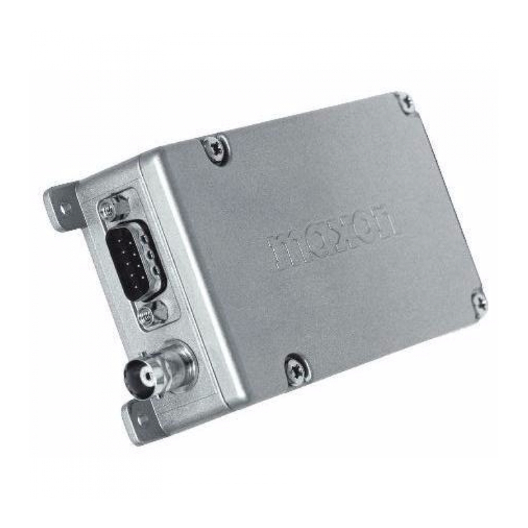
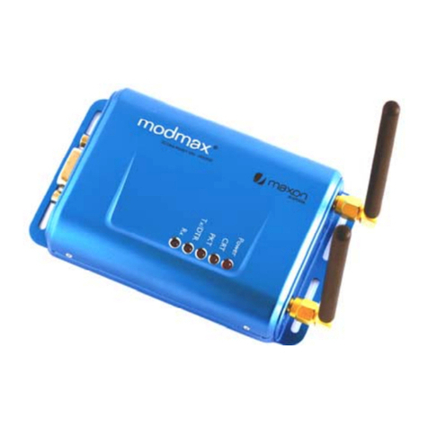
Maxon ACC-513 User manual

ACC-513 / ACC-514
(GMSK / FFSK Modem for SD-160 Series)
Technical Manual
Rev 0.0
Jul./23/2003
Maxon Telecom Co., Ltd

2
Contents
1. Introduction............................................................................... 4
2. Technical Specification............................................................. 5
2.1. Specification for ACC-513............................................................. 5
2.2. Specification for ACC-514............................................................. 6
3. Installation of ACC-513/ACC-514 ........................................... 7
4. System Application................................................................. 10
4.1. Fixed applications.........................................................................10
4.2. Mobile Applications...................................................................... 12
5. Operation ................................................................................ 13
5.1. Serial interface .............................................................................. 13
5.2. Configuring the SD-160 ...............................................................16
6. Understanding Modem Option................................................ 19
6.1. Modem Select ................................................................................ 19
6.2. System Option 1............................................................................ 20
6.3. System Option 2............................................................................ 21
6.4. System Option 3............................................................................ 22
7. Modem Operation Explained.................................................. 23
7.1. Auto Mode.....................................................................................23
7.1.1. Flow Control ........................................................................................... 23
7.1.2. Software flow control.............................................................................. 24
7.1.3. Hardware flow control ............................................................................ 24
7.1.4. None (No flow control)........................................................................... 26
7.2. Dumb Mode................................................................................... 27
7.3. Test Mode ......................................................................................27
7.4. Operating Diagram ......................................................................28

3
8. Example of Operation Test ..................................................... 30
8.1. Example of using Hyper Terminal..............................................30
9. Pin-out chart for ACC-513/514............................................... 40
9.1. Pin-out for ACC-513 .................................................................... 40
9.2. Pin-out for ACC-514 .................................................................... 41
10. product version information.................................................. 42
10.1. Version information....................................................................42

4
1. Introduction
The ACC-513 and ACC-514 are internal option-modems, which are applied to the SD-
160 series to increase capability for data application. The goal of an internal modem is
to improve the efficiency for data transmission and provide maximum flexibility for user
application. The most obvious method of increasing the data efficiency is to maximize
the data signaling speed in the limited channel bandwidth. But, FSK, called direct FM
modulation, has a very wide transmission bandwidth requirement. To solve this problem,
a GMSK(Gaussian Filtered Minimum Shift Keying) internal option-board can be used
Generally a data application can not be directly applied in an audio system (Voice)
Because of its spectra characteristic. The spectra of data has a wider and bandwidth
than audio. So, a direct application of data is not matched with audio system (Voice) and
its application. For instance, if a sub-audio(Tone) SQ system is applied to a data
application, its data frequency spectra will conflict with that of sub-audio tones.
Moreover, the inputted data is filtered by the audio filter resulting in a broken data
transmission. To overcome these problems and provide maximum flexibility, an
FFSK(Fast Frequency Shift Keying) internal option-board modem can be used.
Our internal modem option boards consist of a Slave MCU, Modem IC, and extra
circuitry. These option-boards directly communicate with DTE (Data Terminal
Equipment) to send and receive the meaningful data through the DB-15 connector to
the digital board of the SD-160. These modems are designed to accept RS232 serial
data format and are also capable of high speed wireless data-transmission between two
or more devices. To cope with various applications the SD-160 can be controlled by
automatically or manually. In automatic control the SD-160 will transmit simply by
automatically sending data. The data to be transmitted is automatically stored while the
transmitter is turned on. Before the data is transmitted, a preamble sequence is
transmitted to synchronize the receiving modem. The data is placed in data blocks
(packets) with header and end data information added. In manual control, when the SD-
160 receives data from DTE, the data communication process is almost similar to the
auto mode except that transmission is controlled by a control signal such as PTT or
RTS.


5
2. Technical Specification
2.1. Specification for ACC-513
Modulation type : Modified GMSK
Maximum RF Baud rate : 4800 for 12.5KHz channel spacing and 9600 for
25KHz channel spacing
(Programmable, see below table)
Data Sensitivity : below –113dBm for 1 in 100 error rate
Method for elimination of DC offset : Data scrambling
Data input/output : RS232
RS232 Baud input rate : follow the RF Baud rate (see below table)
Number of Data Bit : 8 bits
Parity : None
Number of Stop Bit : 1 bit
Data flow control : None,
Software(Xon/Xoff),
Hardware(RTS/CTS) (Programmable)
Tx forcing mode : Configures the modem to transmit regardless of
squelch state
Data Block (Packet) size : Programmable from 16bytes to 8192bytes by
multiple of 16bytes increments. To provide
maximum flexibility, the packet doesn’t include
additional bits for error detection and
correction. We recommend that User adds their
own methods for error detection/correction.
Channel Space DTE Baud Rate Modem Baud Rate
Narrow (12.5KHz) 4800 4800
4800 4800
Standard (25KHz)
9600 9600
Table 2.1. Available Baud rate for GMSK modem

6
2.2. Specification for ACC-514
Modulation type : FFSK
Maximum RF Baud rate : 2400 for 12.5KHz channel spacing and 4800 for
25KHz channel spacing
(Programmable, see below table)
Data Sensitivity : below –110dBm for 1 in 100 error rate
Mark /Space tone freq.
(for each available RF Baud rate)
: 1200Hz (M) / 1800Hz (S) at 1200bps
1200Hz (M) / 2400Hz (S) at 2400bps
2400Hz (M) / 4800Hz (S) at 4800bps
Data input/output : RS232
RS232 Baud input rate : follow the RF Baud rate (see below table)
Number of Data Bit : 8 bits
Parity : None
Number of Stop Bit : 1 bit
Data flow control : None, Software(Xon/Xoff),
Hardware(RTS/CTS) (Programmable)
Tx forcing mode : Configures the modem to transmit regardless of
squelch state
Data Block (Packet) size : Programmable from 16bytes to 8192bytes by
multiple of 16bytes increments. To provide
maximum flexibility, packet doesn’t include
additional bits for error detection and
correction.
We recommend that the User adds their own
methods for error detection/correction.
Channel Space DTE Baud Rate Modem Baud Rate
1200 1200 Narrow (12.5KHz)
2400 2400
1200 1200
2400 2400
Standard (25KHz)
4800 4800
Table 2.2. Available Baud rate for FFSK modem

7
3. Installation of ACC-513/ACC-514
To install ACC-513/ACC-514 into the SD-160, this section explains step-by-step of
how to disassemble the radio, install the ACC-513/ACC-514 and reassemble the radio.
Important
Before disassembling and reassembling the radio, wear a conduction wrist strap to
prevent any components on its main board from being damaged by electrostatic
discharge.
Opening the Upper Cover :
1. Unfasten the four mounting screws
located on the bottom cover of the
radio.
Figure 3.1. Loosing the four mounting screws
2. Open slowly the upper cover from the side of
power connector.
Caution : Do not open the upper cover from
the side of DB-15 connector
Figure 3.2. Opening the upper cover

8
Installation of ACC-513/514 :
1. Align 6-pin Header of ACC-513/514 to 6-pin
socket on digital B’D and then push header into
socket
2. Align the 14-pin Molex female connector of
ACC-513/514 to its male connector on the
digital B’D.
3. Attached the ACC-513/514 to the digital B’D
by pushing down.
Figure 3.3. Alignment of ACC-513/514
Figure 3.4. Enlarged drawing
Figure 3.5 Installation of ACC-
513/514

9
Closing the Upper Cover :
1. Align the upper cover with the bottom cover.
2. Close the upper cover.
Figure 3.6. Closing the upper cover
3. Screw down the bottom cover of
the radio.
Figure 3.7. Inserting the four mounting screws

10
4. System Application
The SD-160 is a flexible data radio transceiver intended for a wide variety of
applications. The basic radio data applications may be divided into several categories,
examples of these are :
Point to point telemetry (Data logging system)
Tele-command and tele-control to / from outstations or machinery
Automatic irrigation system
Job allocation and status reporting
Automatic location reporting / polling
Typical function specific systems may include the following :
4.1. Fixed applications
1. Control point to multiple outstation tele-control. Used for control and exception
reporting in water pumping stations and other similar situations. (See Figure 4.1.)
Control Point
Power Supply
Commuication
Interface Cable
Com1
maxon
Antenna
SD-160
Com2
Radio ControlData In/Out
Micro-
Controller
SD-160
To / From
Equipment
Remote Site 1
maxon
+12V PSU
Micro-
Controller
SD-160
To / From
Equipment
Remote Site 1
maxon
+12V PSU
Host
Computer
Figure 4.1. Tele-control Application

11
2. Point to point telemetry using FFSK or GMSK modulation with RS232 control via a
micro-controller. User applications for this may include remote control data links
such as control of a remote paging transmitter or single direction status reporting or
data flow (see Figure 4.2.) from a gas pipeline monitoring station.
Control Point
Power Supply
Commuication
Interface Cable
Com1
maxon
Antenna
SD-160
Com2
Radio ControlData In/Out
Micro-
Controller
SD-160
To / From
Equipment
Remote Site 1
maxon
+12V PSU
Host
Computer Radio Link
Figure 4.2. Telemetry Application
3. Multiple remote sites to control irrigation system (see Figure 4.3.)
Control Point
Power Supply
Commuication
Interface Cable
Com1
maxon
Antenna
SD-160
Com2
Radio ControlData In/Out
Host
Computer
maxon
P
S
U
maxon
Micro-
Controller
Electric
Pump
Water
Tower
Figure 4.3. Irrigation equipment control Application

12
4.2. Mobile Applications
4. Local area mobile system for job allocation and status reporting to and from taxis.
(see Figure 4.4).
SD-160
Radio Link
Taxi 1
Taxi 2
Control Point
Power Supply
Commuication
Interface Cable
Com1
maxon
Antenna
Com2
Radio ControlData In/Out
Host
Computer
Figure 4.4. Job allocation and status reporting Application
5. Marine data communications for ports / harbors and inland waters allowing GPS
navigation information to be relayed from vehicle or vessel to a control point.
Radio Link
Vehicle1
fitted with GPS receiver
and interface
Vessel 1
SD-160
Control Point
Power Supply
Commuication
Interface Cable
Com1
maxon
Antenna
Com2
Radio ControlData In/Out
Host
Computer
Figure 4.5. Vehicle / Vessel Data Application

13
5. Operation
By applying an ACC-513 or ACC-514 to the SD-160, which is intended to be used as a
radio data-generating device utilizing GMSK or FFSK type modulation. There is also a
facility, called Micro-controller Unit, to control your overall application, including the
radio, and to handle data to transmit or receive. The radio is controlled through the DB-
15 connector and interfaces with a DTE by interface cable.
In operation, the radio is placed into the transmit condition by receiving data from DTE.
If the radio receives data, the slave MCU of the ACC-513/514 saves that data in its
memory and automatically creates a PTT signal at the same time to get the RF stage to
prepare for transmission. To avoid data loss in transition time of the RF stage, it is
important that there is a delay between activating the PTT signal and applying the data
to the RF stage. In these processes, there are many tunable parameters, which will be
explained in the next section, to provide maximum performance for user application.
This section describes the basic connection for data transmission or radio control and
then explains important parameters for data transmission.
5.1. Serial interface
In some systems, where data is required to be inputted to a SCADA system or simple
PC logger, the most useful receiver output will be the RS-232 serial stream. Any
system using serial data output will also require DTE(Data Terminal Equipment) such as
a PC, or workstation driver package, or PDA, to display the data and upload it into a
host process. So, To interface with these external equipment, the SD-160 contains a 15
pins D-sub female connector. The serial interface is configured as DCE with the pin out
shown in the table below.
D-Type
Pin No.
Function Description Signal Type Input/
Output
1 Data modulation IN
(Tx Mod)
Signal is directly injected to MOD through
data low pass filter without pre-emphasis.
Analog signal
1KHz audio at 60%
peak system deviation
input level =
100 to 120mVrms
I/P
2 Data unfiltered OUT
(RX disc)
Discriminator audio from the SD-160. This is
the unprocessed AF signal prior to tone
filtering and de-emphasis.
Analog signal
1KHz audio at 60%
peak system deviation
produces
200 to 300mVrms
O/P
3 PTT In Si
g
nal from the ‘external device’ to ke
y
the TTL level I/P

14
(Tx Key) SD-160 transmitter.
This line has an internal pull up resistor to
+5V. Pulling the line to 0V turns on the
transmitter.
Note : If you installed option modem
board, you can select RS-232 signal level
by Jumper (CON407) on the digital
board.
0V = Tx
o/c = Rx
RS-232 level (option)
+12V = Tx
-12V = Rx
4 Ground Ground connection to chassis of the radio. 0V (Chassis)
5 Serial Data Out
(TXD)
Serial data output for radio control or
program.
It uses asynchronous data format.
TTL level O/P
6 Busy
(CD)
Logic level output from the SD-160 to
indicate whether a carrier is present or not
Note : If you installed an option modem
board, you can select RS-232 signal level
by Jumper (CON407, ) on the digital
board.
TTL level
0V = carrier
5V = no carrier
RS-232 level (option)
+12V = carrier
-12V = no carrier
O/P
7 Microphone filtered
audio IN
This signal is injected to the MOD at the
point through audio-amplification, pre-
emphasis and high pass filtering where sub-
audio tone is mixed with audio.
Audio
1KHz audio at 60%
peak system deviation
input level =
6 to 8Vrms
I/P
8 Serial data IN
(RXD)
Serial command or data input for radio
control or program. It uses asynchronous
data format.
TTL level I/P
9 Speaker filtered OUT Audio output from the audio amplifier.
It’s filtered by tone-filter, de-emphasis
circuit.
Audio
1KHz audio at 60%
peak system deviation
produces Nominal
1Vrms @ 8Ω
O/P
10 Serial data IN for
option modem
The Serial data to be transmitted is input to
this pin. It’s only available when option
modem board is installed. Inputted data are
modulated by modem IC and then injected
to MOD.
It uses asynchronous data format.
RS-232 level I/P
11 Serial data Out for
option modem
The recovered asynchronous serial data
output from the receiver. It’s only available
when option modem board is installed. It
uses asynchronous data format.
RS-232 level O/P
12 Serial data busy for
option modem
(reserved)
To eliminate data loss according to buffer
overrun of slave MCU’s memory, it indicates
buffer status.
RS-232 level O/P
13 GPS data input Data input for initial setting of GPS module.
It follows NMEA 0183 format and uses
asynchronous data format.
TTL level I/P
14 DGPS data input Data input for DGPS Correction of GPS
module. It follows NMEA 0183 format and
uses asynchronous data format.
TTL level I/P
15 GPS data output Position data output from the GPS module.
It follows NMEA 0183 format and uses
asynchronous data format.
TTL level O/P
Table 5.1. Pin Description for DB-15 female connector of SD-160

15
The serial protocol supported by the ACC-513/514 is fixed at 1 start bit, 8 data bits, 1
stop bit and no parity. Flow control can be selected as either hardware (RTS/CTS),
software (XON/XOFF) and none. The serial baud rate is also user configurable and
supports the following rates: 1200, 2400, 4800, 9600bps.
According to your application, SD-160 can be connected with one or two serial
communication port of control the unit an through interface cable. Normally, the DB-15
connector of the radio is connected with one communication port of the control unit to
transmit or receive data. But, if you wants additional control such as channel change,
one more communication port is needed to control the radio through serial command.
Figure 5.1. shows an interface cable for data communication and its inner connection. In
the connection, red lines, pins 3, 6 and 12 on the SD-160 are the minimum required
connection to transmit and receive RS-232 data, and blue lines, pins 4,10, and 11 on the
SD-160 are additional connection for handshaking. In Figure 5.2., additional connection
for radio control is added, which needs RS-232 driver to connect the RS-232 serial
port because the radio control signal uses a TTL level to provide compatibility with
former system. Detailed interface information and its use are given in next section.
DB-15
CONNECTOR
DB-9
CONNECTOR
to SD-160 to DTE
1
2
3
4
5
6
7
8
9
RxD
RTS
TxD
CD
CTS
GND
DB-15
CONNECTOR
for Data
Communicaiton
3
4
6
10
PTT IN
GND
BUSY
SERIAL DATA IN (OPT)
11
12
SERIAL DATA OUT (OPT)
SERIAL BUSY OUT (OPT)
DB-9
CONNECTOR
DTE
SD-160
Figure 5.1. Interface cable for data communication and its inner connection

16
DB-15
CONNECTOR
to SD-160
DB-9
CONNECTOR
for Data Communicaiton
DB-9
CONNECTOR
for Radio Control
through Serial command
1
2
3
4
5
6
7
8
9
1
2
3
4
5
6
7
8
9
RxD
RTS
TxD
CD
CTS
3
4
5
6
8
10
PTT IN
GND
SERIAL OUT (PROG.)
BUSY
SERIAL IN (PROG.)
SERIAL DATA IN (OPT)
11
12
SERIAL DATA OUT (OPT)
SERIAL BUSY OUT (OPT)
GNDGND
RxD
TxD
DB-15
CONNECTOR
for Data
Communicaiton
for Radio Control
through Serial
command
RS-232
level
converter DB-9
CONNECTOR
DB-9
CONNECTOR
Figure 5.2. Interface cable for data communication and radio control
5.2. Configuring the SD-160
In case of mobitex application, which is an international and open standard for dedicated
wireless data for professional users, all timing is decided by recommendation of
network system. But, this radio does not use a specific network system. For this reason,
timing parameters will be tuned by the user to fit their own system realization.
5.2.1. Data Transmission (Tx)
If the SD-160 receives data from a DTE, the Master MCU of the SD-160 will get RF
stage to prepare for a transmission. In this case, proper timing is required to stabilize
the RF stage (ex. PLL lock time, Power-up time, and etc.). To prevent data loss,
inputted data will be saved in the internal memory, called a buffer, in the slave MCU of

17
the modem option board by the completion of the RF stabilization. The model contains
tunable value for this period of time, which the user can adjust these timings into their
system within the limited range. Especially, “Tx On delay” and “Tx Off delay” which are
important timing parameters in the transmitter. (see Figure 5.3.)
Tx On delay : The period of time for transmitter’s stabilization before the data is
processed for modulation.
Tx OFF delay : The period of time for avoidance for cutting off the tail end of the
data bit stream.
Data (into SD-160)
P.T.T
Data (into RF Stage)
Tx Delay Time1(Dump mode : Unavailable)
Auto mode : Created by Slave MCU
Dump mode : Inputted by External Equipment
Tx On Delay Tx Off Delay
Inputted Data
Modulated Data
Squelch (Mute) Open
Squelch
Data path open
Recoverd data
Rx On Delay
Recovered Data
TRANSMITTER
RECEIVER
Figure 5.3. Timing parameters in data transmission
5.2.2. Data Reception (Rx)
If the Slave MCU receives a Rx_ready signal from the Master MCU, the Slave MCU on
the modem option board will get the Modem IC to prepare to receive data, at the same
time, the Master MCU releases a Busy detecting signal through the DB-15 Connector.
Before receiving data, the Modem IC or receiver should be synchronized by a

18
transmitted preamble sequence. To prevent synchronization by unwanted signal, a time
delay, called “Rx On Delay”, is needed between squelch open (the point of busy
detection) and data signaling path to Modem (see Figure 5.3.). If insufficient preamble
code is released from another radio, data loss will occur by missing synchronization. So,
a minimum period of time is required for synchronization, this is given by modem IC
specification and you can adjust this value within the limited range. Detailed other
parameters for ACC-513/514 will be given in the next section.

19
6. Understanding Modem Option
In this section, explanation of modem options in ACC 916, PC Programmer is given. The
modem option consists of four groups, MODEM SELECT, SYSTEM OPTION 1,2 and 3.
In MODEM SELECT, the type of modem and modem speed for channel space are
selectable and in SYSTEM OPTION1, transmission mode of radio and functions of
forcing TX and initializing Hyper Terminal are chosen. In SYSTEM OPTION 2, options
for R/TX data format and its processing is selectable. In SYSTEM OPTION3, On/OFF
delay time for R/TX is inputted.
6.1. Modem Select
a. GMSK/FFSK
You can select modem type (GMSK/FFSK). Mark on check box.
b. Modem Enable/Disable
If you want to use modem, click on <Modem Enable> Button.

20
c. Modem Baud Rate
Modem Channel Space Baud rate
9600 bps
Standard (25KHz)
4800 bps
GMSK
(ACC-513)
Narrow (12.5KHz) 4800 bps
4800 bps
2400 bps
Standard (25KHz)
1200 bps
2400 bps
FFSK
(ACC-514)
Narrow (12.5KHz)
1200 bps
Table 6.1. Available Modem Baud Rate
In above cases, Modem speed is selectable.
6.2. System Option 1
a. Auto Mode
The radio will be automatically controlled by existence of inputted data from a DTE.
There is no need for the user to be concerned with operation of the radio. The
SD-160 will transmit simply by sending data.
b. Dumb Mode
The Radio should be controlled by user application, manually. For instance, to
transmit data, you should input PTT(RTS) signal besides assigned data. Moreover,
in control of the radio, exact timing should be defined by you. This mode is only
provided to give compatibility with existent radios.
c. TX Forcing Mode
During RX mode, when the Radio receives data from the DTE, if
TX Forcing Mode
Option is enable, the radio will transmit data. If disabled, the radio will not.
d. Initializing Data for HT (Hyper Terminal)
This is a strongly recommended option when using Hyper Terminal. In addition, you
can check the version of the modem.
This manual suits for next models
1
Table of contents
Other Maxon Modem manuals

Maxon
Maxon MM-5500PRO Instruction manual

Maxon
Maxon MM-6854 Supplement

Maxon
Maxon MA-2020 User manual

Maxon
Maxon MODMAX MM-6280IND Installation instructions

Maxon
Maxon SD125E Series User manual

Maxon
Maxon ACC-513E User manual

Maxon
Maxon Smartmax MA-2010 User manual

Maxon
Maxon Smartmax SDI-12 User manual

Maxon
Maxon Smartmax MA-2010 User manual

Maxon
Maxon Intelimax+4G User manual