RFN ARES RALLY PRO 2023 User manual

RFN ARES RALLY PRO Maintenance Manual
Electric Motorcycle

1
// Table Of Contents
1. Important Cautions...............................................................................
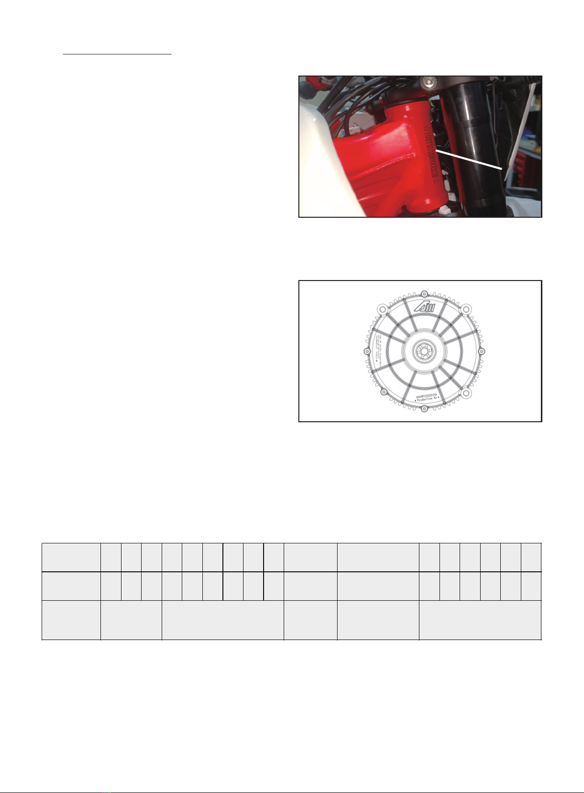
1.1 Serial No. Position............................................................................
1.1.1 Vehicle Identification No.1.1.2 Motor No....................
1.1.2 Motor No......................................................................................
1.1.3 Definition of Vehicle Identification No......................
1.2 General Technological Conditions......................................
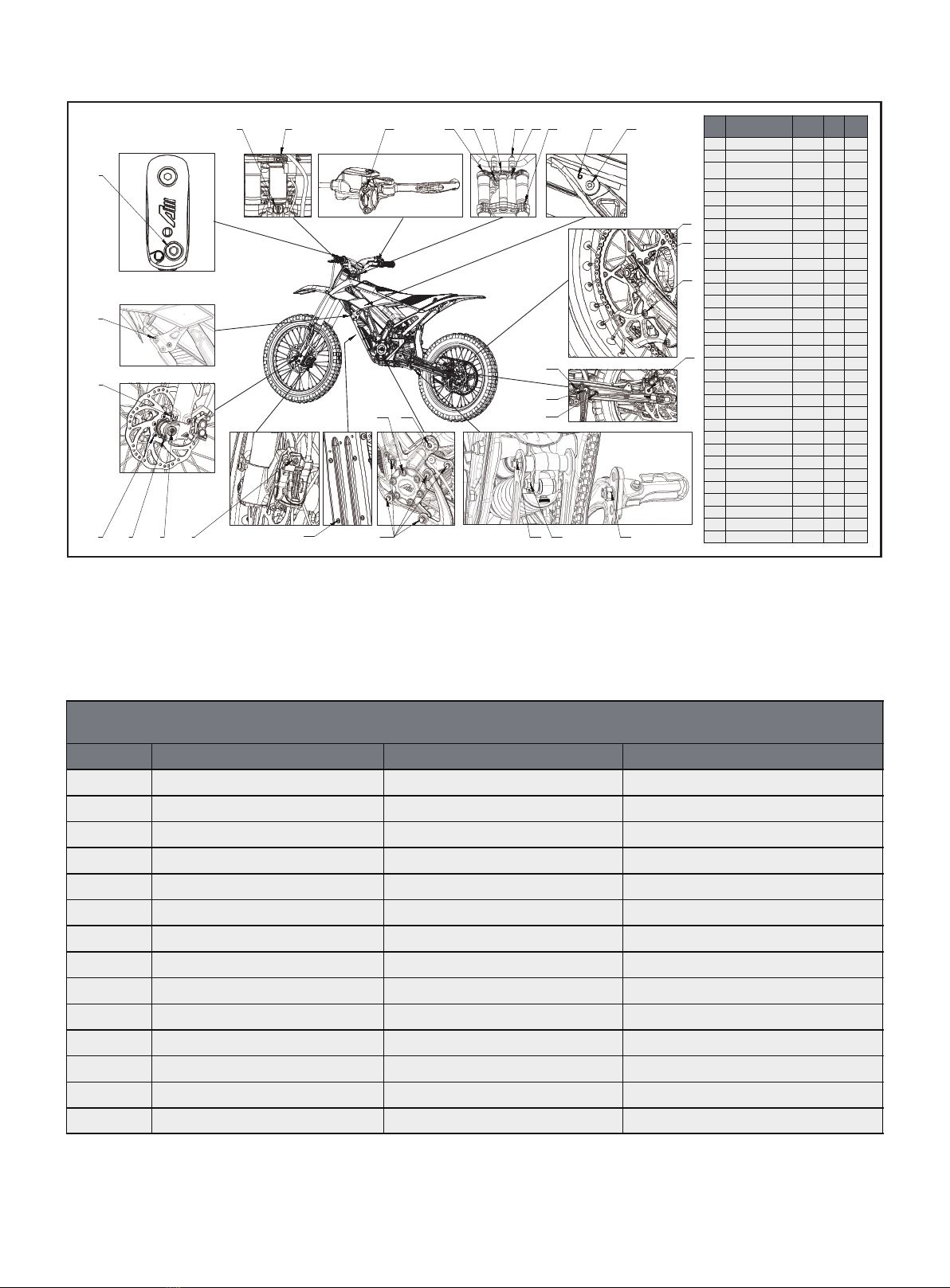
1.2.1 Vehicle Specification...........................................................
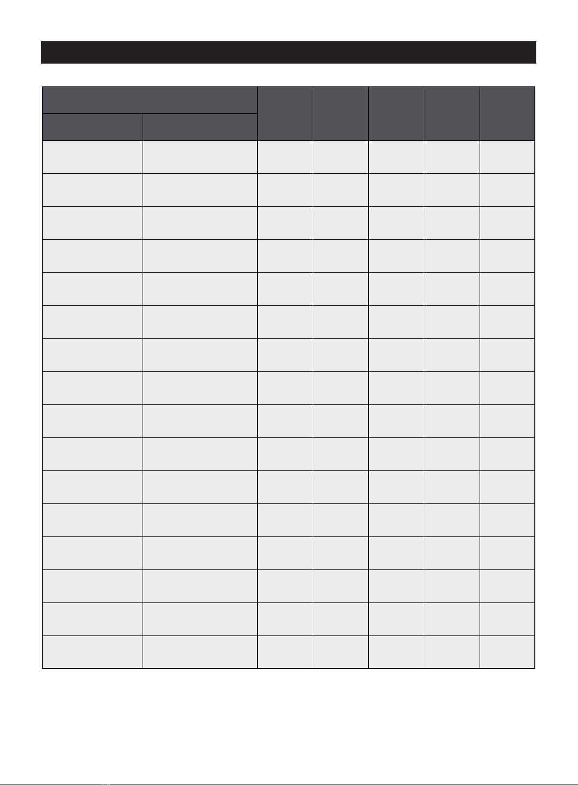
1.2.2 Torque..........................................................................................
1.2.3 Torque Reference................................................................
2. Regular Maintenance........................................................................
2.1 Vehicle Wheel Maintenance....................................................
2.1.1 Inspection on Tyre Pressure..........................................
2.1.2 Inspection on Wheel Axle and Damage of
Wheel Axle...............................................................................
2.2 Brake Maintenance......................................................................
2.2.1 Inspection on Brake Fluid...............................................
2.2.2 Replacement of Brake Fluid.........................................
2.2.3 Inspection on and Replacement of Brake Pad.
2.2.4 Inspection on and Replacement of Front
Brake Disc................................................................................
2.2.5 Inspection on and Replacement of Rear
Brake Disc................................................................................
2.2.6 Replacement of Main Brake Cylinder....................
2.2.7 Replacement of Brake Calliper...................................
2.2.8 Replacement of Brake Line.........................................
2.2.9 Adjustment of Brake Rod..............................................
2.3 Maintenance of Transmission Chain...............................
2.3.1 Inspection on Slackness of Transmission
Chain...........................................................................................
2.3.2 Adjustment of Slackness of Transmission
Chain...........................................................................................
2.3.3 Transmission Chain Lubrication...............................
2.3.4 Inspection on Abrasion of Transmission
Chain...........................................................................................
2.3.5 Replacement of Transmission Chain....................
2.4 Maintenance of Suspension Parts....................................
2.4.1 Inspection on Front Shock Absorber......................
2.4.2 Inspection on Leakage of Damping Oil.................
2.4.3 Inspection on Rear Shock Absorber .....................
2.4.4 Inspection on Leakage of Rear Shock
Absorber.......14
2.5 Maintenance of Steering..........................................................
2.5.1 Inspection on Steering Bearing..................................
2.5.2 Lubrication of Steering Bearing................................
2.6 Electrical Maintenance..............................................................
2.6.1 Maintenance of Battery...................................................
2.6.2 Fuse.............................................................................................
2.6.3 Inspection on Operation of Key Sets.....................
3. Repair and Diagnosis.........................................................................
3.1 Electric System................................................................................
3.1.1 Caution for Operation..........................................................
3.1.2 Caution before Maintenance.......................................
3.1.3 Fault Phenomenon and Fault Shooting.................
3.1.4 Instrument................................................................................
3.1.5 Turn on /o Power Supply.............................................
3.1.6 Switch of Gear........................................................................
2
3
3
3
3
4
4
5
5
6
7
7
8
8
8
8
9
9
10
10
11
11
12
12
12
12
12
13
13
13
13
13
14
14
14
14
14
15
15
15
16
17
17
18
18
19
20
20
20
3.1.7 Lithium Battery, Step for removing the
battery.........................................................................................
3.1.8 Description of Lithium Battery Interface..............
3.1.9 Charge.........................................................................................
3.1.10 Motor..........................................................................................
3.1.11 Controller..................................................................................
3.1.12 Charger.....................................................................................
3.1.13 Electrical Schematic Diagram...................................
3.2 Chassis.................................................................................................
3.2.1 Chassis Exploded View / Parts Location -
Chassis.................................................................................................
3.2.2 Replacement of Chassis................................................
3.2.3 Replacement of Pedal.....................................................
3.2.4 Exploded Vide / Part Location - Seat
Cushion.....................................................................................
3.2.5 Replacement of Seat Cushion...................................
3.3 Wheel and Tyre...............................................................................
3.3.1 Exploded Vide / Part Location - Front Wheel.....
3.3.2 Exploded Vide / Part Location - Rear Wheel.....
3.3.3 Clearing of Fault..................................................................
3.3.4 Rim..............................................................................................
3.3.5 Spoke..........................................................................................
3.3.6 Replacement of Tyre........................................................
3.3.7 Disassembly of Front Wheel and Replacement
of Front Wheel Axle............................................................
3.3.8 Disassembly of Rear Wheel and Replacement
of Rear Wheel Axle.............................................................
3.3.9 Inspection on Wheel Axle..............................................
3.3.10 Inspection on Wheel Axle............................................
3.3.11 Inspection on Rim..............................................................
3.4 Brake......................................................................................................
3.4.1 Exploded View - Part Location - Front Brake......
3.4.2 Clearing of Fault...................................................................
3.4.3 Brake Fluid...............................................................................
3.4.4 Brake Hose.............................................................................
3.4.5 Inspection on Brake Pad................................................
3.4.6 Replacement of Brake Rod..........................................
3.5 Suspension.......................................................................................
3.5.1 Exploded View - Part Location - Front
Suspension..............................................................................
3.5.1 Torque Table...........................................................................
3.5.2 Specification of Front Shock Absorber...............
3.5.3 Replacement of Front Shock Absorbe.................
3.5.4 Replacement of Shock Absorbing Yoke Plate
and Steering Axle...............................................................
3.5.5 Replacement of Electrical Shifter............................
3.5.6 Exploded View/ Part Location - Rear
Suspension............................................................................
3.5.7 Specification of Rear Shock Absorber..................
3.5.8 Clearing of Fault...................................................................
3.5.9 Replacement of Rear Shock Absorber...............
3.5.10 Replacement of Rear Swing Arm...........................
21
22
22
22
22
23
24
25
25
25
26
26
26
27
27
27
28
28
28
28
29
29
30
30
30
30
30
31
31
31
31
32
32
32
33
33
33
34
34
35
35
36
36
37

2
Guarantee
The work specified in the service plan must be performed in an authorized workshop and in accordance with the scope of
the customer’s service card, otherwise no warranty claims can be made. The damage caused by operation and/ or vehicle
modifications can not be covered by the warranty claim service.
Caution and Warning
Please note the notes/ warnings in this Manual.
Failure to take these measures may, result in environmental damage, cause fatal or serious injury, cause extensive
damage to machinery and materials, or even cause fatal or serious permanent injury.
Maintenance Manual
It is important to read this Manual completely before starting work. It contains useful information on how to repair and
maintain your vehicle.
Spare Products, Spare Parts and Accessories
Use only spare parts and accessories that are approved or recommended by KSR Group Ltd.
Practice
Please use professional workshop tools and equipment to maintain and restore your vehicle, with following the instructions
proposed by the manufacturer. After disassembly, clean the parts to be reused and inspect the same for damage and wear,
and if they are damaged or worn, replace such parts.
Important Check
A safety inspection and test drive must be performed after each repair or maintenance job.
Before you hand over the vehicle to the customer, a road safety test must be performed on such vehicle so as to ensure
that the vehicle is in proper deliverable condition.
// 1. Important Cautions

3
1.1.1 Vehicle Identification No.
Frame number (VIN) (1) on the right side of the front riser
1.1.2 Motor No.
Motor number is engraved on the right side of the motor
1.1.3 Definition of Vehicle Identification No.
1.1 Serial No. Position
1
VIN code L 0 8 0 0 0 0 0 1
figures 1 2 3 4 5 6 7 8 9 10 11 12 13 14 15 16 17
construction manufacturer vehicle type model year assembly factory sequential production
number

1.2.1 Vehicle Specification
4
1.2 General Technological Conditions
35Ah / 2.5kWh
LG Premium 21700 lithium cells
Removable, can be charged when installed in bike or separately.
72V
Freewheel, no motor brake
Motor brake with energy regeneration
Stainless steel, 210mm diameter, 2.0mm thickness
Mountain bike disc brakes, two piston calipers, alloy levers. Hand lever for front- and rear brake.
3 hours
2 hours
Variable voltage External charger for 100V-240V outlets
Best-in-class power density and state-of-the-art motor control algorithms.
420 chain with DX
Interior permanent magnet motor
13 teeth
5 kW
12.5 kW**
58 teeth
60N·m
270N·m
Direct drive, chain
24°
320mm - 12.60''
15mm in triple clamps, 43mm in forks
860mm - 33.86''
111mm - 4.37''
1330mm - 52.36''
PP/ABS plastic
6082 aluminium - extruded, forged and CNC machined
200mm
Upside-down air forks featuring 43mm stanchion tubes for extra rigidity and strength, specially developed for .Double shoulder adjustable front damper
14-step adjustable damping
31.8mm
6061 aluminium
22mm
760mm
240mm shock with internals and spring. Used with linkage for optimal performance.Compression damping 9 segments / rebound damping 15 segments
adjustable + Spring preload adjustable
o-road
None / USA, CE / EU
Tortoise mode: The ultimate mode energy conservation exploration. Limited to 25 km/h with 3.5hrs battery range
Rabbit mode: Enduro or active trail riding. 1-2 h riding time
Rocket mode: Track and race mode, maximal torque and speed, riding time up to 1h
Reverse mode: Limited to 9 km/h
Trail/Enduro riding: 3.5 hours
70km/h / 43.5 mph
15 kg
68 kg
170kg (bike + battery + rider)
Forged and CNC aluminium hubs with 20mm axle
F 19"/ R 18" (Motorcycle standard) re-inforced, triple chamber, 7050 aluminium
KENDA
Battery
Brake modes
Brakes
Charging
Controller
Drivetrain
Dimensions
Fenders & Bodywork
Frame
Front suspension
RFN
Handlebar
Rear suspension
RFN
Regulatory
Ride modes
Speed & Range
Weight
Wheels & Tires
RFN
Capacity:
Cells:
Features:
Voltage
Brake mode 1:
Brake mode 2:
Disc:
Type:
0-100%:
0-80%:
Type:
Features:
Chain:
Electric motor:
Front sprocket:
Nominal power:
Peak power:
Rear sprocket:
Torque (motor
Torque (wheel):
Type:
Fork angle:
Ground
Oset:
Seat height:
Trail:
Wheel base:
Material:
Build:
Travel:
Type:
Interface:
Material:
Rise:
Width:
Type:
Classification:
License:
Ride mode 1:
Ride mode 2:
Ride mode 3:
Ride mode 4:
Range:
Top speed:
Battery:
Dry:
Max.
Hubs:
Rims:
Tires:
2.75-19" / 3.0-18" lightweight o-road tires for durability and minimum trail wear
,

1.2.2 Torque
1.2.3 Torque Reference
For the bolts that are not marked with a specific torque other than those specified in the specific torque table, please refer
to the following table for torque tightening. If you loosen a bolt with a thread-tightening adhesive, it must be re-adhered with
a thread-tightening adhesive during assembly, using Loctite ® 243 ™. All operation shall be subject to the specification in the
repair and maintenance manual provided by the manufacturer.
* The value R (strength) indicates the material properties. The lower the value of R, the lower the torque of the bolt.
5
1234
5
6
7
8 9 10 14 15 17
18
19
20
31 25262728
2930
16
12
11 13
22
23
24
21
28
Maximum torque shall refer to ISO 898 / Metric Fastener/ Fraction Coecient 0.12
Size *Strength(R)3.6 *Strength(R)8.8 *Strength(R)12.9
M 1.6 .0470Nm .1690Nm .2850Nm
M 2 .100Nm .350Nm .600Nm
M 2.5 .210Nm .730Nm .120Nm
M 3 .360Nm .120Nm .210Nm
M 4 .820Nm 3.0Nm 5.1Nm
M 5 1.6Nm 5.9Nm 10.0Nm
M 6 2.8Nm 10.1Nm 17.4Nm
M 8 6.8Nm 24.6Nm 42.2Nm
M 10 13.7Nm 48Nm 83Nm
M 12 23Nm 84Nm 144Nm
M 14 37Nm 133Nm 229Nm
M 16 57Nm 206Nm 354Nm
M 18 80Nm 295Nm 492Nm
M 20 112Nm 415Nm 692Nm
1 brake bottom pump M6 4 13-15
2 Front axle side cover M16 2 28-30
3Shock-
absorberLowerCylinder M5 4 8-10
4 Front and rear brake discs M6 12 16-18
5shock-absorber decorate
cover M5 6 4-5
6 Motor guard support M8 4 43-45
7 Third gear switch M4 2 3.5-4.5
8 Plastic part bolt M6 13 4-5
9Steering column upper
cover M24 1 10-15
10 brake upper pump M5 4 8-10
11 upper clamp-01 M8 2 43-45
12 Combination lock M5 2 4-10
13 upper clamp-02 M6 1 13-15
14 handlebar upper holder M8 4 33-45
15 handlebar bottom holder M10 2 51-69
16 bottom clamp M6 4 13-15
17 Front side plate M5 2 3-3.5
18 chain disc M8 5 28-33
19 Rear axle M12 1 85-95
20 Chain guide holder M6 2 8-12
21 foot support limit base M6 1 8-12
22 rear fork center axis M12 1 85-95
23 Foot support bolt
serial
number Position of installation specification quantity
Fastening
torque
value
M10 1 38-55
24 Foot support fixed base M6 1 8-12
25 pedal M10 2 40-45
26 rear shock M8 1 30-40
27 swing arm M8 1 30-40
28 frame-01 M8 7 43-45
29 frame-02 M8 2 38-40
30 rear fork holder support M8 10 35-40
31 controller M6 4 10-13
32 other parts / 5 8-12

// 2. Regular Maintenance
6
*The inspection frequency must be observed, otherwise
the warranty will be invalid.
The 1st
1000KM
Every
1000 KM
Every
3000KM
Every
year
Every 2
years
component activity
display switch Check Check
electric system Check Check Check
battery Check Check Check
front-wheel bearing Check and replace Check Check
rim Check and replace Check Check
brake system Check and replace Check replace
braking line Check Check
brake disc Check, clean and replace Check clean
braking fluid Check and replace Check Check replace
brake pads Check and replace Check replace replace
chain, rear sprocket Check, clean and replace Check and
clean replace
front shock absorber Check and clean Check Check and
clean
rear shock absorber Check and clean Check Check and
clean
steering bearing Check Check Check
side stand Check, clean and lubricate Check, clean
and lubricate
Check, clean
and lubricate
tight of all visible screws
and nuts Check Check Check
,

2.1 Vehicle Wheel Maintenance
2.1.1 Inspection on Tyre Pressure
1. Low Tyre pressure can cause abnormal wear and overheating
2. Tyre pressure should be measured with the tyres colding
(as shown in the figure).
3. Correct tyre pressure ensures optimal ride comfort and
maximum tyre life.
7
Electrical System
Part
Item
Technological Parameter
Battery
Motor
Controller
Rated Voltage
74V
Capacity
35Ah/2590Wh
Voltage
Over-voltage
84V
Under-voltage
56V
Charging Current
Standard
5A
Fast
10A
Charging Duration
Standard
5 6H
Fast
2 3H
Work Temperature
-25 +65
Peak Power
11KW/1400RPM
Type
TOLL Encapsulated power tube
Control Method
FOC SVPWM
Battery Charging Voltage
84V
~
~
~℃
Item Technical Specification Tyre Pressure (bar)
Tyre Pressure
Inner Tyre of Front Wheel
Inner Tyre of Rear Wheel
70/100-19 1.8bar
90/100-18 1.8bar
Measurement Position Item Standard Value (mm) Extreme Value (mm)
Front Axle Curvature 0.2
Front Wheel Lengthways
Horizontal 3mm 3mm
/
/
Oscillating Quantity 2.5mm
<

2.1.2 Inspection on Wheel Axle and Damage of Wheel Axle
1. Dicult wheel rotation, or wheel rotation with a strange noise,
may be caused by the failure of the axle bearing (1) or hub (2) .
2. See (Replacement of front wheel bearing) and (Replacement
of rear wheel bearing) for the steeps of replacing the wheel
bearing.
3. Please replace the wheel assembly if the hub is damaged.
2.2 Brake Maintenance
2.2.1 Inspection on Brake Fluid
1. In the upright position of the vehicle, confirm the position and
cleanliness of the brake pump fluid level observation window.
2. Check the brake assembly for brake fluid leakage at all
locations.
2.2.2 Replacement of Brake Fluid
1. Keep the vehicle in the upright position and make the brake
pump be adjusted to the horizontal position.
2. Remove the protective cover (2) and the internal diaphragm.
3. Add brake fluid to the maximum level (fluid level in contact
with the diaphragm).
4. Install the cover (2) with the internal diaphragm.
* Type of Brake Fluid: Mineral Oil
8
2
1
2
1
1

2.2.3 Inspection on and Replacement of Brake Pad
*Reduce the braking eciency due to worn brake pads. Replace worn brake pads immediately. If need to replace the brake
pads, please replace a pair of such brake pads at the same time, do not just replace a single brake pad.
1. Loosen the mounting bolts (1) of the brake caliper bracket.
2. If the minimum thickness of the brake pad friction material is less than 1.5mm(2), or if there is visible damage or cracking,
the brake pads must be replaced.
3. Loosen the brake pad mounting clips (3)
4. Loosen the brake pad mounting bolts (4)
5. Replace the pair of brake pads.
6. Reassemble in reverse order.
2.2.4 Inspection on and Replacement of Front Brake Disc
1. Replace the brake disc if the thickness of the disc is less than 1.5mm (limit value) at any position or if it is damaged,
cracked or deformed
2. Place a suitable bracket under the vehicle to lift the front wheels.
3. Loosen the fastening screws (1) of the left and right shock absorbing feet.
4. Remove the front axle (2) to remove the front wheel.
5. Unscrew the six screws (3) to remove the front brake disc (4), replace the brake disc screws with new ones and re-add
the thread fastening adhesive.
【Note】Note that the direction indicated by the new brake disc arrow (5) shall be consistent with the direction of
rotation when the wheel is moving forward.
6. Re-assembly by following opposite sequence.
【Note】Always keep the brake disc free of oil and grease, and clean it with brake cleaner if necessary. Residual
grease and stains on the brake discs will aect the braking performance.
* Brake disc tightening bolt torque: 16-18Nm
9
12
3 4
1 2
4 3 5

2.2.5 Inspection on and Replacement of Rear Brake Disc
1. Replace the brake disc when the thickness of the disc is less than 1.5mm (limit value) at any position or if it is damaged,
cracked or deformed
2. Place a suitable bracket under the vehicle to lift the rear wheels.
3. Loosen the adjusting bolt lock nut (1) and loosen the adjusting bolt (2) to remove the axle (3) to remove the rear wheel.
4. Unscrew the six screws (4) to remove the rear brake disc (5), replace the brake disc screws with new ones and re-add
the thread fastening adhesive
【Note】Note that the direction indicated by the new brake disc arrow shall be consistent with the direction of the
brake disc rotation.
5 . Reassemble the new brake disc in reverse order.
* Brake disc tightening bolt torque: 16-18Nm
* Axle tightening torque: 85-95Nm
10
2.2.6 Replacement of Main Brake Cylinder
1. Drain the brake fluid from the hydraulic brake system.
2. Remove the brake oil pipe (2) and the oil pressure switch harness (3) from the master brake cylinder (1).
3. Unscrew and remove the two bolts (4) that connect the brake master cylinder.
4. Remove the brake pump.
5. Replace the defective parts and assemble in a reverse order.
2 1
3
4
3
54
2
1

2.2.7 Replacement of Brake Calliper
1. Remove the oil pipe (1) from the brake caliper.
2. Drain the brake fluid from the hydraulic brake system.
3. Unscrew and remove the two bolts (2) connecting the
brake caliper.
4. Replace the brake caliper.
5. Reassemble in reverse order.
6. Fill the brake fluid.
2.2.8 Replacement of Brake Line
1. Place a container under the brake caliper to hold the used brake fluid.
2. Remove the brake line fitting (1) and empty the brake fluid inside the line.
3. Remove the brake pipe (2) from the main brake pump.
4. Replace the brake hose. Take care that the brake hoses are properly installed and connected to all brackets.
5. Remove the protective cover (3).
6. Add brake fluid to the maximum level.
7. Open the air vent valve (4) and add a brake fluid suction tool to the valve hole. As long as air is in the system, keep adding
brake fluid. Be careful to prevent the brake fluid level in the master brake cylinder from falling below the minimum level,
otherwise, the air will enter into the brake system.
8.Keep pumping air out of the system and keep adding brake fluid until no air bubbles are present in the system.
9. Close the air vent valve and fill the brake fluid level to the maximum level.
10. Reassemble all other components in a reverse order.
【Note】Brake fluid can cause skin irritation when in contact.
Avoid contact with skin and eyes and keep out of the reach of children
Wear appropriate protective clothing and goggles.
If brake fluid gets into your eyes, flush thoroughly with water and contact a doctor immediately.
Brake fluid can damage paint, rubber and plastic parts. When brake fluid drips on these parts, wipe them
o immediately.
【Note】The steps for replacing the front and rear brake hoses are the same
11
1
2
1
2
3
4

2.3 Maintenance of Transmission Chain
2.3.1 Inspection on Slackness of Transmission Chain
1. Check the slackness of the drive chain (A) when the vehicle
is in a upright condition. (Allowable range A: 5- 10 mm)
2.3.2 Adjustment of Slackness of Transmission Chain
1. Loosen the retaining nut (1) of the rear axle.
2. Loosen the adjusting bolt lock nut (2). Use the adjusting
bolts (3) on both sides to adjust the chain until it reaches
the specified slackness of the drive chain.
3. Move the rear wheel several times and check the slackness
of the chain again.
4. Tighten the locknut (2) and tighten the swivel nut (1) of the
rear axle.
Real Axle Torque: 85 - 95 Nm
【Note】The transmission chain and transmission chain
disc need to be replaced together
2.3.3 Transmission Chain Lubrication
【Note】
1. Steam cleaning, high-pressure water gun rinsing, and acidic solvent, will damage the chain.
2. Special chain cleaner and chain lubricant spray could only be used to clean and lubricate the transmission chain.
12
2.2.9 Adjustment of Brake Rod
1. Adjust the brake rod adjusting bolt (1).
2. Narrow the gap between the tie rod and handlebar by
twisting in a counterclockwise way (1), and enlarge the gap
between the tie rod and handlebar by twisting in a
clockwise way (1)
【Note】The steps for replacing the front and rear brake
rods are the same
12
3
1

13
2.3.4 Inspection on Abrasion of Transmission Chain
1. Stretch the chain to a taut state and measure the center
distance of ten links (A)
2. When the measurement result exceeds the maximum
value 129.1mm, replace the chain immediately.
2.3.5 Replacement of Transmission Chain
1. Loosen the rear axle.
2. Open the chain lock of the damaged drive chain (1).
3. Install the new chain in the reverse order.
4. Install the chain in the reverse order and pay attention to
the correct adjustment of the slackness of the chain.
【Notes】The open side of the chain lock (2) must be
installed in the opposite direction of rotation (arrow).
2.4 Maintenance of Suspension Parts
2.4.1 Inspection on Front Shock Absorber
1. Check whether each screw of the suspension system is
tightened.
2. Apply the front brake and compress the front shock
absorber (arrow) up and down to check whether the front
shock absorber could work in a proper way.
3. Check whether the shock core of the shock absorber is
damaged or loose.
4. When the shock damping fails, it cannot absorb the
vibration normally, or there are other abnormalities please
replace it in a timely manner.
2.4.2 Inspection on Leakage of Damping Oil
1. Check the dust seal/ oil seal and replace the damaged
shock absorber when the shock absorber oil leaks.
【Note】Make sure the fixing bolts of front shock
absorber are in tight condition at each inspection.
2
A

14
2.4.3 Inspection on Rear Shock Absorber
1. Check that each screw is tightened.
2. Compress the rear shock absorber up and down to check
for proper function (arrows).
3. Check whether the shock core of the rear shock absorber
is damaged or loose.
4. Place the vehicle on the main stand and move the rear
wheels up and down to check whether the bushings or
bearings are loose or have abnormal slackness.
5. When the damping of the shock absorber fails, it cannot
absorb the vibration normally, or there are other
abnormalities, please replace it in a timely manner.
2.4.4 Inspection on Leakage of Rear Shock Absorber
1 . Check the dust seal/oil seal and check if the spring is
normal, When the damping oil leaks, the dust seal/oil seal
will break or wear out, and please replace the damaged
damper seals.
2.5 Maintenance of Steering
2.5.1 Inspection on Steering Bearing
1. Place a bracket under the vehicle to raise the front wheels
o the ground.
2. Hold the lower ends of the front shock absorber and try to
move them back and forth (arrows). Turn the forks in both
directions and check the steering head for any abnormal
openness or clamping.
3. In case of any abnormal openness or clamping, replace the
steering bearings.
2.5. Lubrication of Steering Bearing
1. Place the vehicle on a level surface.
2. Remove the number plate, gauges, handlebars and upper
shock absorber coupling plate.
3. Lift the vehicle or lower the front forks.
4. Lubricate the steering bearings (1). Please use only high
quality grease to prevent grease loss.
5. After bearing lubrication, assemble the parts in a reverse
order.
6. If the steering bearing is damaged, please replace the
steering bearing, see (Replacement of Shock Absorber
Coupling Plate and Steering Bearing ) for steps.
1

15
2.6 Electrical Maintenance
2.6.1 Maintenance of Battery
1. Always keep the battery to be charged. Storing a depleted battery will cause permanent damage to the battery.
2. If the vehicle has not been used for more than one month, remove the battery from the vehicle to recharge it, as
described in the (Lithium Battery) section, and store it in a dry place at 0-40° C. Keep the battery charge at 30%-40%.
3. If the battery is stored for more than two months, check the battery level at least once a month and recharge the battery
if necessary. The battery needs to be charged for two hours every three months.
4. Charge the battery before inserting the battery back.
2.6.2 Fuse
【Note】To avoid short circuit, always turn the main key o when checking or replacing the fuse.
1. Open the master key to verify that the circuit is operable. Under the trim cover (1). In the fuse socket (2) , contains the
main fuse (3) and the backup fuse (4)
2. Open the fuse socket (2) and replace it with a new fuse.
3. If the fuse is fused again immediately, check the circuit.
【Note】Do not use fuses whose fusing current does not match the rated value, which may cause extensive
damage to the electrical system and cause a fire.
Fuse
Fusing Current
Main Fuse
10A
Spare Fuse
10A
1
24 3

16
2.6.3 Inspection on Operation of Key Sets
1. Place the vehicle on the stand so that the rear wheels are o the ground, and then start the vehicle.
【Note】Please unlock the vehicle P gear and enter the “ready” gear
2. Test the function of all switches one by one
3. If the function of the keys is abnormal, check the key set and the circuit system
Functions of Keys
1.Rocket mode
2. Turtle / Rabbit mode switch
3. R backup
21
3

3.1 Electric System
// 3. Repair and Diagnosis
17
Motor Parameter
Battery Parameter
Item
Type / Specification
Rated Busbar Voltage
74V
Rated Power
5 kW
Peak Power (10min)
11kW@1400rpm
Rated Service Speed
2200rpm
Max Service Speed
3000rpm
Rated Torque
21.7N•m
Peak Torque
58N•m
Rated Phase Current
80A
Peak Phase Current
350A
Max Motor Eciency
93%
Insulation Grade
F
Type of Sensor
Magnetic encoders
Protection Level
IP67
Cook Method
Air cooling
Reduction Gear Ratio
5.27
Weight
9.7kg
Operation Mechanism
S9 Non-periodic changes in load and speed
Work Temperature
-25 ~+60
Storage Condition
-40 ~+65
( )
℃ ℃
℃ ℃
Item
Type / Specification
Battery Parameter
Type of Battery
Ternary lithium battery
Normal Voltage
3.7V
4.8Ah@25 0.5/3C charge and discharge 4.2V~2.75V
Max. Voltage
4.2V
Min. Service Voltage
2.8V
Battery System Parameter
Tandem or Parallel Method
20S7P/ 20 tandem 7 parallel
Normal Voltage of System
74V
Voltage Range
56V~84V
Normal Capacity
35Ah
Min. Capacity
33.6Ah
Direct Resistance
65.7m @50% SOC 2C
Max. Charging Current
10A
Max. Charging Voltage
84V
Max. Rated Discharge Current
85A
Peak Discharge Current
150A for 9sec
Insulation Resistance
@DC500V 200M
Impulse Withstand Voltage
No spark, no breakdown @50Hz~60Hz 1500VAC 1min
Service Temperature
Charging Temperature
-5 ~45
Discharging Temperature
-20 ~60
℃
≤ Ω
≥ Ω
℃ ℃
℃ ℃
,
( )
( )

18
3.1.1 Caution for Operation
1. When checking the lithium battery to be used, make sure there is no abnormality in the lithium battery first.
2. The on/o test of the switch can be inspected and measured in the car body installation state of the switch.
3. After the inspection and overhaul of each part, the cable and lanyard should be passed correctly according to the
lanyard and cable wiring diagram. It is forbidden to carry out maintenance work on the three electric parts when the
whole car is in the electric state.
4. Before maintaining the high-voltage components, you must hold relevant documents and wear complete high-voltage
protective equipment.
3.1.2 Caution before Maintenance
Electric vehicle-specific voltages are high-voltage of which shall exceed 36V safety voltage. In such a case, careful
operation and backup support are required when performing rescue work. When repairing or handling the vehicle-specific
voltage system, please prepare at least the following safety protection means:
1. insulated protective equipment, including insulated gloves, protective glasses, insulated shoes, etc.
2. ABC dry powder fire extinguisher.
3. solvent-resistant protective equipment, including gas masks for organic gases, chemical-resistant rubber gloves, etc.
4. rags, towels.
【Note】If the vehicle-specific voltage cable parts are damaged and the wiring and terminals are exposed, do not
touch the exposed parts under any circumstances. In addition, do not touch the exposed wiring or terminals if you
are not sure whether the damaged is an electric motorcycle-specific voltage component.
Contacting the wiring or terminals without proper safety precautions may result in serious burns or electric shock
causing serious injury or death.
If contacting with exposed parts of electric motorcycle-specific voltage cables or voltage components is
necessary, or if there is a risk of contact, insulated protective equipment (insulated gloves, protective glasses,
insulated shoes) that can withstand electric motorcycle-specific voltage must be used.
When the person concerned is separated from the vehicle, e.g. when storing the vehicle after an accident, please
put a sticker on the body of the vehicle saying “Under Operating. Do not touch!” to avoid serious safety accidents
caused by other person inadvertently touching the vehicle.

19
3.1.3 Fault Phenomenon and Fault Shooting
Turn on the
power, the ready
light can not be
activated
1.Single brace fails to be retracted
or single brace switch encounters a
failure
1.Retract the single brace or replace the single brace switch
2. Brake switch encounters a
failure 2.Unplug or replace the brake switch
3.Emergency switch is damaged or
the key is not put back 3. Put back the hand type key or replace the switch
Turn on power,
activate the
ready light, motor
does not work
1.Battery failure 1.Check whether the connection cable is firmly connected or
replace the battery
2.Controller failure 2. Reconnect and tighten the connection at the maintenance
oce or replace the controller
3. Motor failure 3. Reconnect and tighten or replace the motor at the
maintenance oce
4. Speed control handle failure or
not to zero position 4. Check the turnbuckle plug wire connection or replace
5. Brake power-o switch is
damaged to turn on 5. Check the brake handle and brake switch
Speed regulation
is not working or
maximum speed
is low
1. Battery power is below 20%, and
the vehicle will enter into the turtle
gear
1. Fully charge the battery
2. Battery temperature is higher
than 60 or lower than 0
2. Wait until the battery temperature is lower than 55 and
higher than 0
3. Controller temperature is higher
than 90 3. Wait for the controller temperature below 80
4. Motor temperature is higher than
120 4. Wait for the motor temperature below 120
5. Speed control handle failure 5. Repair the after-sales service to replace the speed control
handle
The range is not
enough after
charging once
1. Tyre pressure is insucient 1. Tyres charged to the appropriate air pressure
2. Insucient charging or charger
failure 2. Sucient power or check the charger plug contact
3. Improper brake adjustment,
driving resistance is too large 3. Readjust the brake
4. Battery aging or damage 4. Replace the battery
5. Go uphill, headwind, frequent
acceleration and deceleration,
heavy load
5. Under the use of the environment, reducing the battery life
is the normal phenomenon
Charger does not
work
1. Battery under-voltage (lower
than 44V) or output short circuit 1. Restore the voltage to 56V or more or replace the battery
2. Battery over-voltage (higher
than 85V) 2. Reduce the voltage to 84V or less or replace the battery
3. Battery positive and negative
reverse connection or battery
overheating
3. Check the connection plug,
Serial No. Fault
Phenomenon
Instrument
Code Cause for Fault Shooting Method
1
2
3
4
5and wait until the battery
temperature is below the limit
4. Charger failure 4. Wait for the charger temperature below the limit or replace
5. Charger plug o or loose
connection
5. Check whether the charging input and output plugs are well
connected
1. 10
2. 20
3. 30
4. 50
1.Two
indicators
for battery
power are
left
2. 11 12
3. 21
4. 31
5. 50
1. Two lights
flashing
2.Three
lights
flashing
3.Four lights
flashing
4. Five lights
flashing
℃ ℃
℃
℃
℃℃
℃℃
Other manuals for ARES RALLY PRO 2023
1
Table of contents
Other RFN Motorcycle manuals