RFN ARES RALLY PRO 2023 User manual

RFN ARES RALLY PRO OWNER'S MANUAL
Original Instructions
ELECTRIC
DIRT BIKE

1
To all RFN owners:
Thank you for your trust to the RFN brand, we will accompany you to make exploration of the life as much as possible, look for unknown answers and wonderful
off-road life.
This manual explains the correct and safe use of the vehicle and a simple inspection before using. Please read the operation instructions carefully. If you have
any questions about the operation or maintenance of your vehicle, please contact an authorized dealer
1. Introduction

2
2. Important Manual Information
Warning
It refers to a warning instruction to be abided by and failure of abiding by the warning may result in serious injury or death of the vehicle operator.
Caution
Warning refers to a special precaution to avoid damage to the vehicle and it indicated the important information in this manual.
Caution
Please always leave this manual to the next owner for maintenance/service records, even if the vehicle is sold out. This manual contains most of the information
related to the vehicle. However, the manufacturer will continue to improve its product design and quality which may result in differences between the manual and the
actual vehicle. If you have any questions about this, please consult your dealer.
Warning
The instructions in this User Manual are prepared for your own safety. Please read this User Manual carefully before operating the vehicle to ensure that you have a
thorough understanding of how to operate and control. Only if you have an offcial driver’s license and good training can you have the ability to safely drive this vehicle
Otherwise, do not drive this vehicle to avoid injury.
Please maintain the vehicle in accordance with the prescribed vehicle maintenance interval so as to ensure the safety and prolong the service life of the vehicle.
*Products and specifications will be subject to change without separate notice
Safety depends, to a large extent, on riding skills.
The following requirements shall be abided by the driver:
The driver shall receive good driving training in all functions of the vehicle with the necessary technical instruction for off-road riding, as well as wear the protective
gear for off-road equipment, and when driving, please do not drink alcohol.
Please read all maintenance instructions in the User Manual.
The vehicle shall only be repaired by an authorized dealer.

3
3. Safe Driving.........................................................................................................................................................................................................................................................4
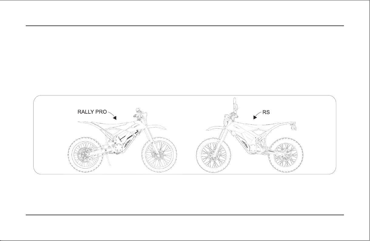
4. Description of Vehicle Parts...............................................................................................................................................................................................................................6
5. Manufacturer Information..................................................................................................................................................................................................................................8
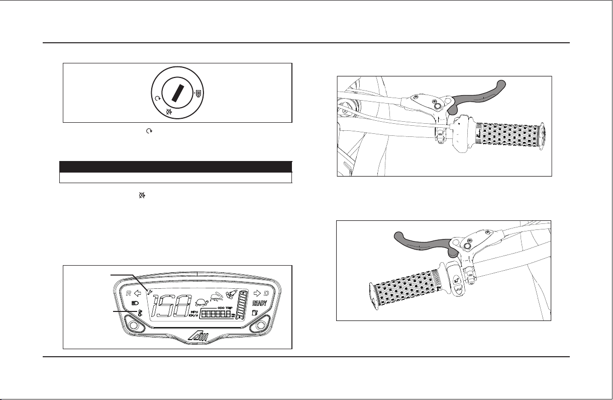
6. Display and control devices..............................................................................................................................................................................................................................9
7. Inspection before riding...................................................................................................................................................................................................................................15
8. Riding operation...............................................................................................................................................................................................................................................16
8.1 Starting.....................................................................................................................................................................................................................................................16
8.2 Riding.......................................................................................................................................................................................................................................................16
8.3 Throttle.....................................................................................................................................................................................................................................................17
8.4 Braking.....................................................................................................................................................................................................................................................17
8.5 Selecting a riding mode..........................................................................................................................................................................................................................18
8.6 Parking.....................................................................................................................................................................................................................................................18
9. Regular maintenance and minor repairs.......................................................................................................................................................................................................19
9.1 Tires..........................................................................................................................................................................................................................................................19
9.2 Braking System.......................................................................................................................................................................................................................................21
9.3 Lubricating the brake levers...................................................................................................................................................................................................................22
9.4 Side stand................................................................................................................................................................................................................................................22
9.5 Suspension components.......................................................................................................................................................................................................................22
9.6 Steering Bearing Inspection...................................................................................................................................................................................................................23
9.7 Wheel bearings.......................................................................................................................................................................................................................................23
9.8 Chain Tension..........................................................................................................................................................................................................................................23
9.9 Battery.......................................................................................................................................................................................................................................................24
9.10 Fuses......................................................................................................................................................................................................................................................24
10. Trouble shooting.............................................................................................................................................................................................................................................25
11. Cleaning and storage....................................................................................................................................................................................................................................26
12. Technical Specifications...............................................................................................................................................................................................................................28
13. Guarantee and warranty...............................................................................................................................................................................................................................29
14. After-sales service and warranty coverage table........................................................................................................................................................................................30
15. Maintenance guideline..................................................................................................................................................................................................................................41
16. Service Manual..............................................................................................................................................................................................................................................42
Table Of Contents

4
3. Safe Driving
Check the condition of the vehicle and its surroundings before starting so as to
avoid accidents.
Do not lend the vehicle to a driver who is not fit to drive the vehicle.
Correct posture is important to maintain balance.
Grasp the handlebars with both hands, keep your upper body upright, and keep
both feet on the pedals
Do not ride after drinking alcohol or taking drugs
Anti-armor
Please wear riding armor with protective features. off-road armor is required
for driving this type of vehicle to prevent injury as much as possible.
Helmet
Your helmet constitutes the most important components of your protective
gear. A well-tested helmet can prevent the driver from serious head injuries
caused by accidents. Professional off-road helmets shall be worn properly.
Goggles
Ordinary glasses and sunglasses are not enough for providing adequate
protection. Professional goggles for off-road helmets are required.
Off-road gloves
Professional off-road gloves with functions of joint protection and knuckle
protection are required to reduce the degree of hand injury in the event of an
accident.
Boots
Professional, sturdy, high-top off-road boots are required to improve leg and
foot protection and riding safety.
Clothing
Professional long sleeves and pants shall be wore to protect your arms and
legs. The off-road suits and armor could provide better protection.
Modifications
Modifying or removing original parts from a vehicle that has not been
approved by the manufacturer may make it less safe and cause serious
injury. You are responsible for the consequences caused by such kind of
modification and removal.
Caution for Load
Adding accessories or increasing the load can lead to changes in weight
distribution, affecting steering and balance which easily lead to the traffc accidents.
Standard Load
Max Load Capacity <120 kg
When loading locates within this limit, please remember the followings:
The center of gravity of work shall be kept as low as possible. Distribute the
weight as evenly as possible to maintain balance.
Loads must be securely attached to the vehicle.
Do not hang the heavy or bulky objects on the handlebars or forks which
may cause imbalance and slow steering response of the vehicle.

5
Accessories
The manufacturer will only use the original accessories supplied by the
manufacturer for your vehicle. Please contact an authorized dealer for this
purpose. The manufacturer refuses to bear any and all responsibilities and
duties for the accessories provided by third party and all of such
responsibilities and duties shall be assumed by you.
When installing accessories, please remember the following:
Do not install any accessory or transport any load that obstructs or limits
ground clearance, suspension travel, steering, lighting, indicators or reflectors.
Accessories installed on handlebars or front wheel suspension may impair
the steering performance. Please keep the accessories to be installed as light
as possible.
Do not install any luggage rack that may affect the stability of the vehicle when
facing the wind.
Electrical accessories have been installed by an authorized dealer to match
the capacity of the electrical system.
Improper installation may result in loss of lighting,low motor power reduction
and vehicle damage.
Other Safety Instructions
Drive slowly and brake carefully on wet roads or slick surfaces.
3. Safe Driving
Safety Stickers
1.Warning stickers of driving behavior
2.Warning stickers of major switch
3.Warning stickers of battery
4.Warning stickers of air pressure
5.Warning stickers of use

6
4. Description of Vehicle Parts
Left side view
1. Charging port
2.Battery fixing lock
3.Frame
4.Rear fender
5.Rear shock absorber
6.Front wheel
7.Front brake assy
8.Front suspension fork
9.Motor controller
10.Lithium battery pack
11.Side stand
12.Rear swing arm
13.Rear brake assy
14.Rear wheel
8
6
7
9
5 12 11
13
14
4
11032

7
Top view
16. Handlebar
17.Rear brake lever
18.Instrument panel
19. Front brake lever
20.Acceleration twist throttle
21.Master key switch
22.Seat
4. Description of Vehicle Parts
22 20
19
21
17
16
18

8
5. Manufacturer Information
Manufacturer
Name:Zhejiang Apollo Sports Technology Co., Ltd.
Add:No.12-14 of Jinheng Second Road,Jinyanshan Industrial Zone,Quanxi
Town,Wuyi County,Jinhua City,Zhejiang Province,China
Power Rating
DC brushless motor
Waterproof grade:IP67
Insulation grade:F
Rated speed:2,200r/min
Rated power:5KW
Rated voltage:72V
Code:10000-BEll-111Y
Designed by AM
L08Y10T06N1000009
★ Vehicle Serial Number ★
Vehicle Serial Number
Please note that the vehicle serial number SN will be used when ordering
spare parts from an authorized dealer or in the event of theft of the vehicle.
It is engraved on the right side of the steering head tube of the frame.
Vehicle Serial Number

9
6.1 Main Switch Controls Power:
6.2 Power on Turn the key to “ ” position
The meter will light up, after retracting the side stand, “Ready” on meter
lights up, it can be ridden normally.
Attention
If the side stand is put down, it will not be able to unlock P gear for riding
6.3 Turn off Turn the key to “ ”
All electrical systems are turned off
6.4 Fault Warning
1. When a fault occurs, the speed will turn into a blinking fault code indicating
the specific fault; The fault indicator blinks when a fault occurs.
2. When the battery, motor and controller exceed the limit temperature, the
overtemperature warning light will be on.
6. Display and control devices
6.5 The brake lever for the front brakes is located on the right handlebar.
6.6 The brake lever for the rear brakes is located on the left handlebar. In
case of applying the brakes, pull the lever toward the handlebars.
Fault indication
Overtemperature
warning light

10
6. Display and control devices
6.7 The button mechanism on the handlebars
Rocket mode (1
Tortoise/Rabbit mode switch (2
R reverse (3
1.Rocket mode
The vehicle will run at peak power, and this mode will be maintained for
9s at a time.It will automatically enter the original mode after 9s.
2. Switch between the tortoise mode and rabbit mode: click once to switch
between tortoise mode and rabbit mode; when soc <20 %, it will
automatically enter into the tortoise mode, rabbit mode and rocket mode
will automatically prohibit triggering.
* The dynamic mark indicates the current status. If the indicator is on long,
it indicates that the user can enter. If the indicator is off, it indicates that
the user cannot enter.
3. Reverse: enter the reverse mode after long press 2 seconds when the
vehicle is stationary, max speed <9km/H
6.8 Side stand
Side stand(1) is located on the left side of the vehicle.
Open the side stand to make the vehicle upright.
It's on the left side of the vehicle. Open the side stand to make the
vehicle upright. P gear cannot be unlocked when the side stand is open.
After the vehicle stands for three minutes, the vehicle enters P gear
without power output (hold the brake levers for 2s and unlock it to enter
forward gear)
1
32
1
3
1
2
3

11
6.9 Battery Charger
The vehicle is equipped with the battery charger. If there is only one red
indicator light left on the meter, please charge the vehicle immediately.
Only the factory-supplied charger could be used to charge the battery.
There are two charging modes (corresponding to the relevant indicator
lights), and the charging rate can be adjusted by pressing and holding the
button on the charger for 2 seconds. The charging rate can be switched
between 10A or 5A.
6. Display and control devices
6.10 Charging Port
The charging port (1) is located on the battery.
The battery can be charged when it is mounted on or removed from the
vehicle. It is recommended to cover the charging port dust cover when not
charging to avoid foreign objects entering and damaging the charging port or
corroding the charging port and other dangerous situations.
Note
The indicator light has the function of status indication and fault indication.
1
Empty load Battery Unconnected Fast charging indicator and Slow charging indicator flash
Charging
Press the current switching button, the charging current can be switched
between 5A and 10A (when the BMS specifies the charging current is less
than 5A, press the current switching button to be invalid)
A total of 5 bar (20% -100%) capacity indicator, the corresponding indicator that are currently
charging flash, the completed capacity indicator are often on; when the current switch button is
changed ,the fast charging or slow charging indicator shows the corresponding 10A/5A status
Fast charging indicator and Slow charging indicator goes off;
All capacity indicators are often on
error indication
Battery under voltage or short -circuit (battery voltage is lower than 44V) The 20% and 40% battery capacity indicator flickering faster
Battery overvoltage (battery voltage is
Item Charging status battery voltage Indicator Status
Charging current
1
2
3
4 higher than 85V) The 20% ,40% and 60% battery capacity indicator flickering faster
Battery anti -connection or overheating alarm The 20% ,40% , 60% and 80% battery capacity indicator flickering faster
Charger fault (power supply overvoltage, overcurrent, overheating) The 20%,40% ,60% ,80% and 100% battery capacity indicator flickering faster
Battery fully charger
charge mode button charge current LED Battery Indicator

12
6.11 Battery
The battery is located under the battery cover.
Note: Please observe the warning on the battery, including: battery
charging working temperature: 0~45℃, battery discharging
working temperature: -20℃~55℃
The battery with low remaining power shall be fully charged before
placing it aside for a long time, it is recommended to charge the battery every
30 days when it is not in use, and the battery may enter into the hibernation
mode due to low power for more than 90 days without use.
After entering the hibernation mode, the battery can be activated by the
charger: first plug in the charger, and then connect the charger to the main
supply.
6.12 The arc power indicator has 10 cells, each cell corresponds to 10%
power, decreasing from right to left.
1 cell: remaining 10% power, the charging indicator flashe,please
charge it immediately.
2 cells: remaining 20% power
3 -10 cells: remaining 30% - 100% power
Backlight switch button used to turn on/off the backlight of the instrument
Speed and mileage unit switch button used to switch speed and mileage unit
Do not disassemble or bump the battery.
Do not leave the battery in an environment of which temperature fails
to locate in the range of -25 ~ 70°C.
Do not put the battery with unconnected or unsealed ports into liquids
such as water, acid, alkali, salt water, etc.
Please read the warning on the battery carefully before use.
Warning!
Please charge the battery on a regularly basis
Avoid completely using up the battery.
Do not turn on the battery while it is being charged in the vehicle.
If the battery power drops below 20%, the power will be limited and the
vehicle will enter into the tortoise mode in a forced manner.
Please charge the battery immediately if the power drops below 10%!
Otherwise, it might cause irreparable damage.
Warning!
Caution
6. Display and control devices
Backlight
switch
Speed、
mileage
unit switch
button

13
6.13 Operation on Charging the Battery
1. Turn off the vehicle.
2. Insert the charger plug into the battery.
3. Insert the power plug into a 220 V socket.
4. The charger indicator will operate while the battery is charging.
5. When the battery is fully charged, the charger power indicator will be
fully illuminated and the operating noise will be reduced.
6. Disconnect the plug.
6. Display and control devices
6.14 Remove the battery
Remove the cushion (1
Open the locking mechanism (2
Take off the battery cover (3
Unplug the communication plug (4
Unplug the power supply (5
Lift up the battery (6
6.15 Insert the battery
Insert the batteries in reverse order.
Please note that never drain the battery until it is completely depleted,
otherwise, it will permanently damage the battery. A damaged battery
caused by over discharge due to improper operation cannot be
repaired and must be replaced at the expense of user.
Warning!
Be careful
Charge the battery regularly
To avoid completely draining the battery charge
Do not turn on the battery while it is charging in the vehicle.
1
2
3
5
4
6

14
6.16 Front Shock Adjustment
The knob above the front shock absorber is responsible for rebound
damping adjustment
The knob below the front shock absorber is responsible for the
compression damping adjustment.
6.17 Adjusting the rear shock
Adjusting the rear shock preload
To adjust the spring preload of the damper, please turn the adjusting
knob on the top of the damper (1)
On the lower side of the damper is the rebound adjustment knob (2).
The adjustment knob for compression damping (3) is located at the
top of the shock
* The rebound damping knob controls the damping during rebound.
If theknob is turned clockwise, the shock rebound is slower.
If the knob is turned counterclockwise, the shock rebound will be faster.
* The compression damping adjustment knob controls the damping
during compression. If the knob is turned clockwise, the compression
of the damper becomes stiffer. If the knob is turned counterclockwise,
the compression of the shock becomes softer.
* The rebound damping knob controls the damping during rebound.
If the knob is turned clockwise, the shock rebound is slower. If the
knob is turned counterclockwise, the shock rebound will be faster.
* The compression damping adjustment knob controls the damping
during compression. If the knob is turned clockwise, the compression
of the damper becomes stiffer. If the knob is turned counterclockwise,
the compression of the shock becomes softer.
6. Display and control devices

15
7. Inspection before riding
If a part of the vehicle is found to be defective, do not ride the vehicle.
The manufacturer does not provide any warranty for problems caused
by negligence of authorized dealers or lack of care and maintenance
of the vehicle user.The manufacturer does not provide any warranty
for damage to the vehicle or safety accidents due to violation operation.
Warning!
Caution
For your safety, please check the condition of your vehicle before
each use so as to avoid safety incidents caused by vehicle failure.
7.1 Check list before riding
Carry out a check when the vehicle is at a standstill.
When you squeeze the brake, you must not hold the brake lever all the way close to the handlebars.
The braking system must work with a constant pressure. If it takes several repeated pull of the brake lever to achieve the required
braking force, contact an authorized dealer to inspect the brake system.
Check the brake lines for fluid leaks.
Check the brake pads. If the brake pads are worn to only 1 mm at any point, replace two pads
Brake System
Items to be checked Contents to be checked
Side Stand
Tire
Check whether the wheels are running properly.
Check whether the tires are damaged and the treads of tires are too shallow
Check tire pressure and correct if necessary
Throttle Check whether the function of the throttle is normal, and the rotation is smooth without jamming. Whether the return position is normal.
Body and Hanging Device
Check the operating status. If the vehicle power is on and the throttle lever is turned, the side stand must be folded.
Check whether the bolts, nuts and screws are tight
Chassis
Check the function of the shock absorbers by compressing them several times. Also check the front and rear shock absorbers for leaks and dirt.
Apply the front brakes and push down on the handle several times to check whether the front shocks are working properly. Press the seat hard
several times to check whether the rear shock absorber is working properly.
Display and Lighting
Check whether all lights on the display and vehicle are working properly. It is especially important in order to be noticeable to other traffic participants.
Battery Make sure the battery is always fully charged before use.
Steering Check whether there are no faults and lubricate the steering pivot if necessary

16
8.2 Riding
1. Retract the side stand
2. Sit on the seat.
3. Squeeze and hold the brake lever for more than 2 seconds and the
meter shows ready status (Or take away the emergency power off switch
for 2 seconds and put back after the “ready” lights up)
4. Slowly turn the throttle (right) to start riding.
Before departure, please familiarize yourself with all of the control
components of the vehicle and how to operate them Contact your
dealer if you have any questions.
Warning!
8.1 Starting
Turn the key to ‘ ’
Caution
Make sure the battery is properly installed and fully charged.
8. Riding operation
A
B

17
8.3 Throttle
To accelerate, turn the throttle to the direction (a); To decelerate, turn the
throttle to the direction (b), and use the brake.
8.4 Braking
Turn the throttle fully (b) with no tendency to continue accelerating.
Use the front and rear brakes simultaneously and increase the braking
force evenly
8. Riding operation
Avoid sudden or violent braking, which can cause the vehicle’s tires to
skid.
Braking distances will be extended when braking is applied on slippery
surfaces.
Avoid traveling in bad weather such as heavy rain.
Drive on dry roads. Slowly descend slopes
Control the vehicle and avoid overheating the brakes
Warning!
Rear Wheel Brakes Front Wheel Brakes
A
B

18
8. Riding operation
8.5 Selecting a riding mode
Use the Riding Mode button to select from three modes:
Tortoise mode: In this mode, power delivery is limited under which the
tortoise icon on the meter will flash
Rabbit mode: In this mode, the available power is greater under which
the rabbit icon on the meter will flash
Rocket mode: Press the rocket button to turn on this mode. After turning
on the mode, the maximum power output will last for 9 seconds under which
the rocket icon on the meter will flash
8.6 Parking
Turn off the main switch of the vehicle
Put down the side stand.
Make sure that the vehicle is parked on a stable and level ground
Warning!
Rocket mode
indicator

19
The safety and condition of your vehicle are influenced by the proper
maintenance, regular inspections, adjustments and lubrication. In the following
pages, you will refer to the corresponding instructions. Maintenance
information can help you with preventive maintenance and minor repairs.
However, some maintenance operations require special tools.
9. Regular maintenance and minor repairs
9.1 Tires
For optimal performance, durability and safe operation of your tires,
please refer to the following tire instructions.
Tire pressure
Tire pressure must be checked before each trip and corrected if
necessary. Check tire pressure on a regular basis.
Do not perform any maintenance work that you are not familiar with or
that could affect the warranty service
Warning!
Changes to your vehicle that are not authorized by the manufacturer may
result in changes to the vehicle’s performance and affect safe driving. If the
customer makes such changes without the manufacturer’s authorization, the
warranty claim would be invalid.
Make sure the tires are at room temperature when checking tire pressure.
Please check the tire pressure before each trip to ensure that the tire pressure
is at a normal level
Caution
Maintenance work must be done by authorized professional distributors
Tire Pressure
Front Tire
Rear Tire
1. 8Bar
1. 8Bar
Do not overload your vehicle. The higher the load on the vehicle, the
higher the pressure when the tires rotate and the higher the resistance
of the tires, brakes and steering. This can lead to damage or accidents.
A reasonable weight distribution on your vehicle is important for
your safety!
Warning!
Other manuals for ARES RALLY PRO 2023
1
Table of contents
Other RFN Motorcycle manuals