RFS INSTALLATION GUIDELINES
HYBRIFLEX®CABLE|603400210500|September 2020
Visit www.rfsworld.com for the most current product specifications
Page 9 of 43
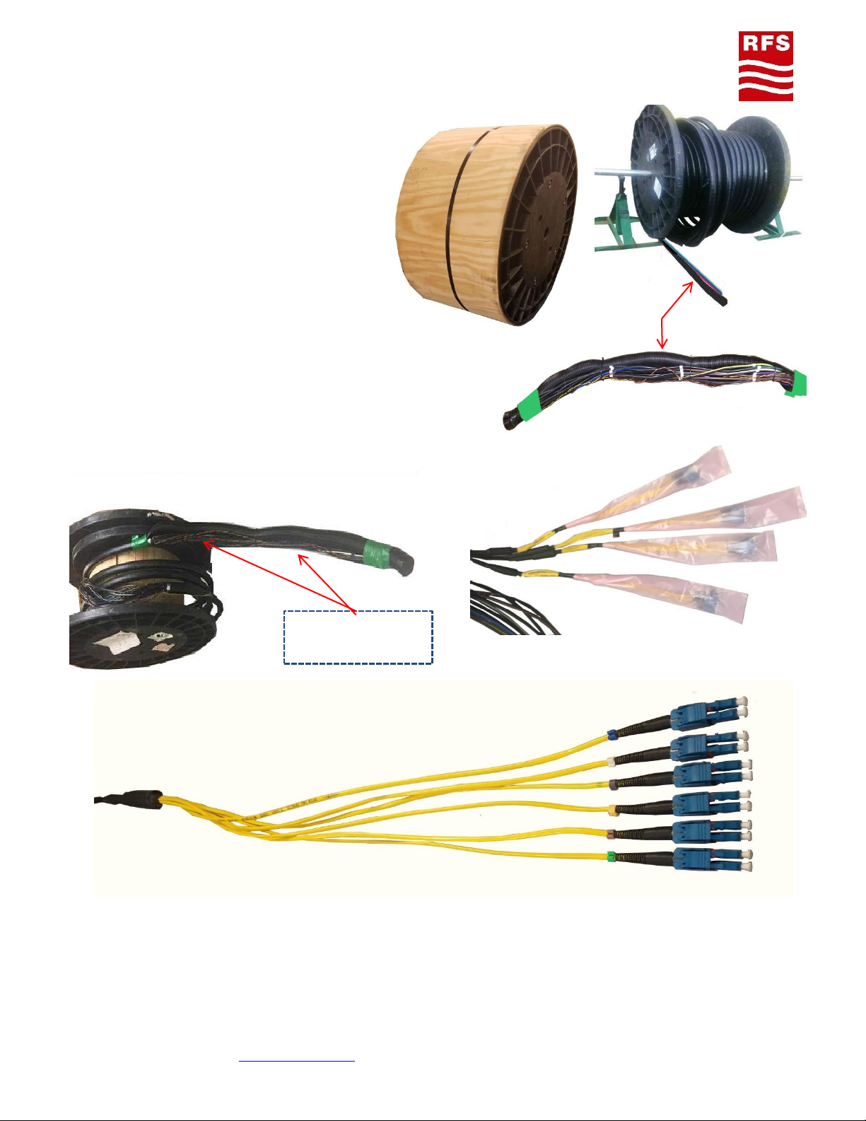
Transporting, Shipping and Handling the Drum
Drums must be handled carefully to avoid any damage to the drum and/or the hybrid cable.
•If the drum will be shipped by van or truck the drum must be secured against rolling. Pay special
attention to careful loading and unloading. Do not roll the drum from high levels (load floor) of the
vehicle without protective measures, e.g. roll the drum from the vehicle by using planks as a ramp. Do
not drop the drum!
•If forklifts are used, the forks must be long enough to engage both flanges of the drum at the same
time to avoid cable damage.
•If a crane is used, a special hanger is necessary to ensure vertical application of forces and thus
avoiding damage of the drum flanges and the cable.
•Do not lay the drum on its side, reels must be transported and handled in their up-right position only
(the cable could be deformed due to its own weight).
•Make sure that the cable end is always properly sealed and fixed as close as possible to the drum core.
•Note the recommended rotation direction of the drum, which is shown by an arrow on the drum
flange (during installation/pulling of the cable the drum will be on drum stands and will then be
turned in the opposite direction to unwind the cable).
•If the drum is completely protected by wooden planks, these should not be removed before the drum
is placed (transported) to the final position.
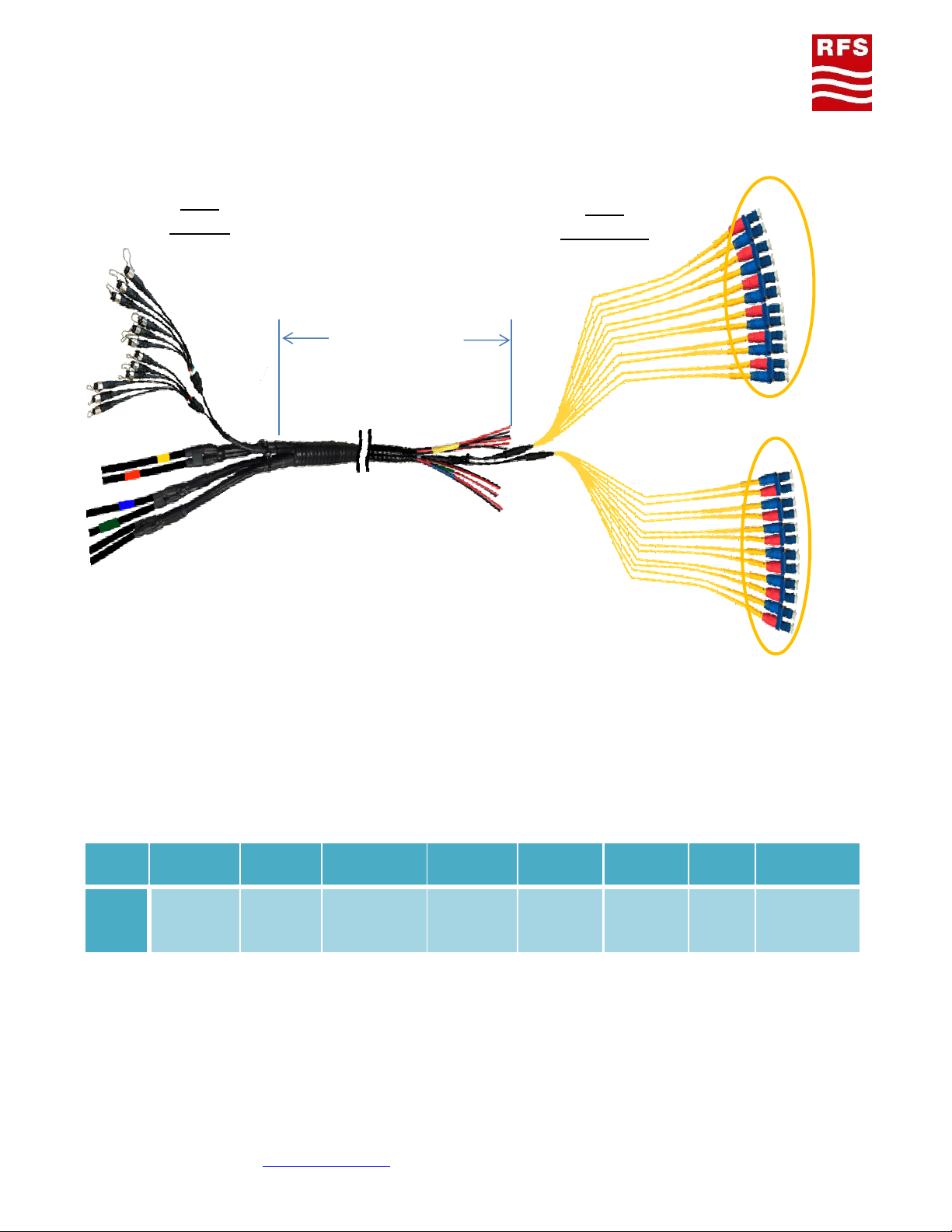
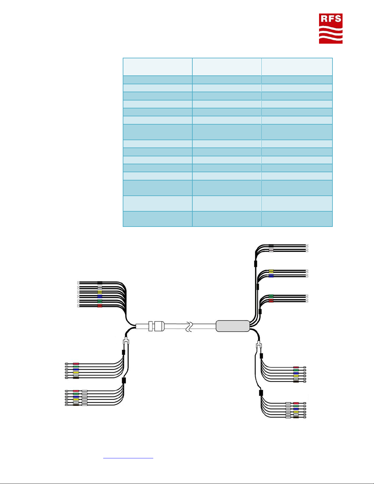
Handling HYBRIFLEX Cable
Upon receiving the HYBRIFLEX shipment it is highly
recommended that the drum be inspected for any
physical damage and all fiber connection points be
tested.
Do not drag the cable over sharp edges. If, it can’t be
avoided to drag the cable over sharp edges, protective
measures must be taken, if necessary by positioning an
additional rigging at those critical places.
To protect the cable against any damage, protective
measures must be taken. This is also applicable if cables
must be pulled in horizontal runs (example: using pipe
rollers, wooden planks or similar).
Prevent any pinches to the DC wires, which may cause
electrical spikes and shorten circuitry.