Rheem RBHP-17A00NH1 User manual

INSTALLATION INSTRUCTIONS
92-20521-44-06
SUPERSEDES 92-20521-44-05
WARNING
▲WARNING
!
These instructions are intended as an aid to qualified licensed
service personnel for proper installation, adjustment and
operation of this unit. Read these instructions thoroughly before
attempting installation or operation. Failure to follow these
instructions may result in improper installation, adjustment,
service or maintenance possibly resulting in fire, electrical
shock, property damage, personal injury or death.
ISO 9001:2008
AIR HANDLERS
(-)BHP
• MODELS FEATURING R-22 REFRIGERANT
• MODELS FEATURING EARTH-FRIENDLY R-410A REFRIGERANT
• MODELS FEATURING ELECTRIC HEAT WITHOUT INDOOR
COOLING COIL
refrigerant

2
TABLE OF CONTENTS
1.0 SAFETY INFORMATION . . . . . . . . . . . . . . . . . . . . . . . . . . . . . . . . . . . . . . . . . . . . 3
2.0 GENERAL INFORMATION . . . . . . . . . . . . . . . . . . . . . . . . . . . . . . . . . . . . . . . . . . 7
2.1 Important Information About Efficiency and Indoor Air Quality. . . . . . . . . . . . 7
2.2 Receiving. . . . . . . . . . . . . . . . . . . . . . . . . . . . . . . . . . . . . . . . . . . . . . . . . . . . 8
2.3 Clearances. . . . . . . . . . . . . . . . . . . . . . . . . . . . . . . . . . . . . . . . . . . . . . . . . . . 8
2.4 Model Number Explanation . . . . . . . . . . . . . . . . . . . . . . . . . . . . . . . . . . . . . . 9
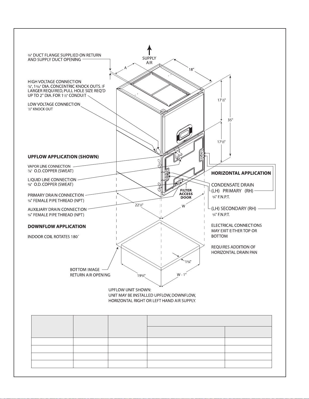
2.5 Dimensions and Weights. . . . . . . . . . . . . . . . . . . . . . . . . . . . . . . . . . . . . . . 10
2.6 Unit Configuration . . . . . . . . . . . . . . . . . . . . . . . . . . . . . . . . . . . . . . . . . . . . . . . . . 11
2.7 Vertical Upflow. . . . . . . . . . . . . . . . . . . . . . . . . . . . . . . . . . . . . . . . . . . . . . . 12
2.8 Vertical Downflow. . . . . . . . . . . . . . . . . . . . . . . . . . . . . . . . . . . . . . . . . . . . . 12
2.9 Horizontal. . . . . . . . . . . . . . . . . . . . . . . . . . . . . . . . . . . . . . . . . . . . . . . . . . . 14
3.0 ELECTRICAL WIRING. . . . . . . . . . . . . . . . . . . . . . . . . . . . . . . . . . . . . . . . . . . . . 15
3.1 Power Wiring . . . . . . . . . . . . . . . . . . . . . . . . . . . . . . . . . . . . . . . . . . . . . . . . 15
3.2 Control Wiring . . . . . . . . . . . . . . . . . . . . . . . . . . . . . . . . . . . . . . . . . . . . . . . 16
3.3 rounding . . . . . . . . . . . . . . . . . . . . . . . . . . . . . . . . . . . . . . . . . . . . . . . . . . 16
3.4 Blower Motor Electrical Data: “A” Voltage . . . . . . . . . . . . . . . . . . . . . . . . . . 17
3.5 Blower Motor Electrical Data: “J” Voltage . . . . . . . . . . . . . . . . . . . . . . . . . . 17
3.6 Electric Heat Electrical Data . . . . . . . . . . . . . . . . . . . . . . . . . . . . . . . . . . . . 17
4.0 DUCTWORK. . . . . . . . . . . . . . . . . . . . . . . . . . . . . . . . . . . . . . . . . . . . . . . . . . . . . 19
5.0 REFRIGERANT CONNECTIONS . . . . . . . . . . . . . . . . . . . . . . . . . . . . . . . . . . . . 20
5.1 Flowcheck Pistons. . . . . . . . . . . . . . . . . . . . . . . . . . . . . . . . . . . . . . . . . . . . 20
6.0 CONDENSATE DRAIN TUBING . . . . . . . . . . . . . . . . . . . . . . . . . . . . . . . . . . . . . 21
7.0 AIR FILTER . . . . . . . . . . . . . . . . . . . . . . . . . . . . . . . . . . . . . . . . . . . . . . . . . . . . . 22
8.0 AIRFLOW PERFORMANCE . . . . . . . . . . . . . . . . . . . . . . . . . . . . . . . . . . . . . . . . 22
8.1 Airflow Operatng Limits . . . . . . . . . . . . . . . . . . . . . . . . . . . . . . . . . . . . . . . . 23
8.2 Airflow Performance Data . . . . . . . . . . . . . . . . . . . . . . . . . . . . . . . . . . . . . . 23
9.0 SEQUENCE OF OPERATION . . . . . . . . . . . . . . . . . . . . . . . . . . . . . . . . . . . . . . . 25
9.1 Cooling (cooling only or heat pump) . . . . . . . . . . . . . . . . . . . . . . . . . . . . . . 25
9.2 Heating (electric heat only) . . . . . . . . . . . . . . . . . . . . . . . . . . . . . . . . . . . . . 25
9.3 Heating (heat pump) . . . . . . . . . . . . . . . . . . . . . . . . . . . . . . . . . . . . . . . . . . 25
9.4 Watt Restrictor . . . . . . . . . . . . . . . . . . . . . . . . . . . . . . . . . . . . . . . . . . . . . . . 25
9.5 Defrost Sequence . . . . . . . . . . . . . . . . . . . . . . . . . . . . . . . . . . . . . . . . . . . . 25
9.6 Emergency Heat (Heating of Heat Pump) . . . . . . . . . . . . . . . . . . . . . . . . . . 26
9.7 Room Thermostat (Anticipator Setting) . . . . . . . . . . . . . . . . . . . . . . . . . . . . 26
10.0 CALCULATIONS . . . . . . . . . . . . . . . . . . . . . . . . . . . . . . . . . . . . . . . . . . . . . . . . . 26
10.1 Calculating Temperature Rise . . . . . . . . . . . . . . . . . . . . . . . . . . . . . . . . . . . 26
10.2 Calculating BTUH Heating Capacity . . . . . . . . . . . . . . . . . . . . . . . . . . . . . . 26
10.3 Calculating Airflow CFM. . . . . . . . . . . . . . . . . . . . . . . . . . . . . . . . . . . . . . . . 26
10.4 Calculating Correction Factor . . . . . . . . . . . . . . . . . . . . . . . . . . . . . . . . . . . 26
11.0 PRE-START CHECKLIST . . . . . . . . . . . . . . . . . . . . . . . . . . . . . . . . . . . . . . . . . . 27
12.0 MAINTENANCE . . . . . . . . . . . . . . . . . . . . . . . . . . . . . . . . . . . . . . . . . . . . . . . . . . 27
12.1 Air Filter . . . . . . . . . . . . . . . . . . . . . . . . . . . . . . . . . . . . . . . . . . . . . . . . . . . . 27
12.2 Indoor Coil-Drain Pan-Drain Line. . . . . . . . . . . . . . . . . . . . . . . . . . . . . . . . . 28
12.3 Blower Motor and Wheel . . . . . . . . . . . . . . . . . . . . . . . . . . . . . . . . . . . . . . . 28
12.4 Lubrication . . . . . . . . . . . . . . . . . . . . . . . . . . . . . . . . . . . . . . . . . . . . . . . . . . 28
12.5 Blower Assembly Removal and Replacement. . . . . . . . . . . . . . . . . . . . . . . 28
12.6 Electric Heater Replacement. . . . . . . . . . . . . . . . . . . . . . . . . . . . . . . . . . . . 29
12.7 Motor Replacement . . . . . . . . . . . . . . . . . . . . . . . . . . . . . . . . . . . . . . . . . . . 29
13.0 REPLACEMENT PARTS . . . . . . . . . . . . . . . . . . . . . . . . . . . . . . . . . . . . . . . . . . . 30
14.0 ACCESSORIES - KITS - PARTS . . . . . . . . . . . . . . . . . . . . . . . . . . . . . . . . . . . . . 31

3
1.0 SAFETY INFORMATION
Improper installation, or installation not made in accordance with the Underwriters
Laboratory certification or these instructions, can result in unsatisfactory operation
and/or dangerous conditions and are not covered by the unit warranty.
!WARNING
DO NOT, UNDER ANY CIRCUMSTANCES, CONNECT RETURN DUCTWORK TO
ANY OTHER HEAT PRODUCING DEVICE SUCH AS FIREPLACE INSERT,
STOVE, ETC. UNAUTHORIZED USE OF SUCH DEVICES MAY RESULT IN FIRE,
CARBON MONOXIDE POISONING, EXPLOSION, PERSONAL IN URY OR PROP-
ERTY DAMAGE.
!WARNING
DISCONNECT ALL POWER TO UNIT BEFORE INSTALLING OR SERVICING.
MORE THAN ONE DISCONNECT SWITCH MAY BE REQUIRED TO DE-ENER-
GIZE THE EQUIPMENT. HAZARDOUS VOLTAGE CAN CAUSE SEVERE PER-
SONAL IN URY OR DEATH.
!WARNING
BECAUSE OF POSSIBLE DAMAGE TO EQUIPMENT OR PERSONAL IN URY,
INSTALLATION, SERVICE AND MAINTENANCE SHOULD BE PERFORMED BY
A TRAINED, QUALIFIED SERVICE PERSON. CONSUMER SERVICE IS RECOM-
MENDED ONLY FOR FILTER CLEANING/ REPLACEMENT. NEVER OPERATE
THE UNIT WITH THE ACCESS PANELS REMOVED.
!WARNING
PROPOSITION 65: THIS APPLIANCE CONTAINS FIBERGLASS INSULATION. RES-
PIRABLE PARTI CLES OF FIBERGLASS ARE KNOWN TO THE STATE OF CALI-
FORNIA TO CAUSE CANCER.
!CAUTION
When installing a unit with cooling coil over a finished ceiling and/or living
space, installation of an auxiliary drain pan under the entire unit, to avoid dam-
age to ceiling, is recommended.
!WARNING
THESE INSTRUCTIONS ARE INTENDED AS AN AID TO QUALIFIED, LICENSED
SERVICE PERSONNEL FOR PROPER INSTALLATION, SET UP AND OPERA-
TION OF THIS UNIT. READ THESE INSTRUCTIONS THOROUGHLY BEFORE
ATTEMPTING INSTALLATION OR OPERATION. FAILURE TO FOLLOW THESE
INSTRUCTIONS MAY RESULT IN IMPROPER INSTALLATION, SET UP, SERVICE
OR MAINTENANCE POSSIBLY RESULTING IN FIRE, ELECTRICAL SHOCK,
PROPERTY DAMAGE, PERSONAL IN URY OR DEATH.
!WARNING
Duct leaks can create an unbalanced system and draw pollutants such as dirt,
dust, fumes and odors into the home causing property damage. Fumes and
odors from toxic, volatile or flammable chemicals, as well as automobile
exhaust and carbon monoxide (CO), can be drawn into the living space
through leaking ducts and unbalanced duct systems causing personal injury
or death (see Figure 1).
• If air-moving equipment or ductwork is located in garages or off-garage stor-
age areas - all joints, seams, and openings in the equipment and duct must
be sealed to limit the migration of toxic fumes and odors including carbon
monoxide from migrating into the living space.
• If air-moving equipment or ductwork is located in spaces containing fuel
burning appliances such as water heaters or boilers - all joints, seams, and
openings in the equipment and duct must also be sealed to prevent depres-
surization of the space and possible migration of combustion byproducts
including carbon monoxide into the living space.

4
!WARNING
IF UNIT IS TO BE INSTALLED WITHOUT AN INDOOR COIL, RETURN DUCT OR
PLENUM, IT MUST NOT BE IN STALLED DIRECTLY OVER COMBUSTIBLE MATE-
RIAL. IF INSTALLED WITHOUT AN INDOOR COIL WITH A RETURN DUCT OR
PLENUM, THE AIR PLENUM OR DUCT MUST HAVE A SOLID SHEET METAL
BOTTOM WITH NO RETURN AIR OPENINGS, REGISTERS OR FLEXIBLE AIR
DUCTS LOCATED DIRECTLY UNDER THE UNIT. EXPOSING COMBUSTIBLE
MATERIAL TO THE RETURN OPENING OF AN UPFLOW UNIT WITHOUT AN
INDOOR COIL CAN CAUSE A FIRE RESULTING IN PROPERTY DAMAGE, PER-
SONAL IN URY OR DEATH.
!WARNING
THE RXBB-AA COMBUSTIBLE FLOOR BASE IS REQUIRED WHEN SOME
UNITS WITH ELECTRIC HEAT ARE APPLIED DOWNFLOW ON COMBUSTIBLE
FLOORING. FAILURE TO USE THE BASE CAN CAUSE A FIRE RESULTING IN
PROPERTY DAMAGE, PERSONAL IN URY OR DEATH. SEE CLEARANCES
FOR UNITS REQUIRING A COMBUSTIBLE FLOOR BASE.
!WARNING
THE FIRST 36 INCHES OF SUPPLY AIR PLENUM AND DUCTWORK MUST BE
CONSTRUCTED OF SHEET METAL AS REQUIRED BY NFPA 90B. THE SUPPLY
AIR PLENUM OR DUCT MUST HAVE A SOLID SHEET METAL BOTTOM
DIRECTLY UNDER THE UNIT WITH NO OPENINGS, REGISTERS OR FLEXIBLE
AIR DUCTS LOCATED IN IT. IF FLEXIBLE SUPPLY AIR DUCTS ARE USED THEY
MAY BE LOCATED ONLY IN THE VERTICAL WALLS, OF A RECTANGULAR
PLENUM, A MINIMUM OF 6 INCHES FROM THE SOLID BOTTOM. METAL
PLENUM OR DUCT MAY BE CONNECTED TO THE COMBUSTIBLE FLOOR
BASE, IF NOT, IT MUST BE CONNECTED TO THE UNIT SUPPLY DUCT
FLANGES SUCH THAT COMBUSTIBLE FLOOR OR OTHER COMBUSTIBLE
MATERIAL IS NOT EXPOSED TO THE SUPPLY AIR OPENING FROM THE
DOWNFLOW UNIT. EXPOSING COMBUSTIBLE (NON-METAL) MATERIAL TO
THE SUPPLY OPENING OF A DOWNFLOW UNIT CAN CAUSE A FIRE RESULT-
ING IN PROPERTY DAMAGE, PERSONAL IN URY OR DEATH.
EXCEPTIONS TO DOWNFLOW WARNINGS:
• INSTALLATIONS ON CONCRETE FLOOR SLAB WITH SUPPLY AIR PLENUM
AND DUCTWORK COMPLETELY ENCASED IN NOT LESS THAN 2 INCHES OF
CONCRETE (SEE NFPA 90B).
• INSTALLATIONS OF UNITS WITHOUT ELECTRIC HEATERS.
!WARNING
THE SUPPLY AIR PLENUM OR DUCT MUST HAVE A SOLID SHEET METAL
BOTTOM WITH NO SUPPLY AIR OPENINGS, REGISTERS OR FLEXIBLE AIR
DUCTS LOCATED IN IT FOR THE FIRST 36 INCHES OF HORIZONTAL SURFACE
ON UNITS WITH ELECTRIC HEATERS. FAILURE TO OBSERVE SUPPLY
PLENUM, DUCT WARNINGS CAN CAUSE A FIRE RESULTING IN PROPERTY
DAMAGE, PERSONAL IN URY OR DEATH.
!WARNING
(SEE WARNINGS IN REGARD TO DUCTWORK)
DO NOT INSTALL THIS UNIT IN MANUFACTURED (MOBILE) HOMES.
IMPROPER INSTALLATION IS MORE LIKELY IN MANUFACTURED HOUSING
DUE TO DUCTWORK MATERIAL, SIZE, LOCATION, AND ARRANGEMENT.
INSTALLATIONS IN MANUFACTURED HOUSING CAN CAUSE A FIRE RESULT-
ING IN PROPERTY DAMAGE, PERSONAL IN URY OR DEATH.
EXCEPTION: MANUFACTURED HOUSING INSTALLATIONS ARE APPROVED
ONLY WITH DOCUMENTATION BY A RECOGNIZED INSPECTION AUTHORITY
THAT THE INSTALLATION HAS BEEN MADE IN COMPLIANCE WITH THE
INSTRUCTIONS AND ALL WARNINGS HAVE BEEN OBSERVED.

5
!WARNING
THE UNIT MUST BE PERMANENTLY GROUNDED. FAILURE TO DO SO CAN
RESULT IN ELECTRICAL SHOCK CAUSING PERSONAL IN URY OR DEATH.
!WARNING
UNITS WITH CIRCUIT BREAKER(S) MEET REQUIREMENTS AS A SERVICE
DISCONNECT SWITCH, HOWEVER, IF ACCESS IS REQUIRED TO THE LINE
SIDE (COVERED) OF THE CIRCUIT BREAKER, THIS SIDE OF THE BREAKER(S)
WILL BE ENERGIZED WITH THE BREAKER(S) DE-ENERGIZED. CONTACT WITH
THE LINE SIDE CAN CAUSE ELECTRICAL SHOCK RESULTING IN PERSONAL
IN URY OR DEATH.
!WARNING
IF REMOVAL OF THE BLOWER ASSEMBLY IS REQUIRED, ALL DISCONNECT
SWITCHES SUPPLYING POWER TO THE AIRHANDLER MUST BE DE-ENER-
GIZED AND LOCKED (IF NOT IN SIGHT OF UNIT) SO THE FIELD POWER
WIRES CAN BE SAFELY REMOVED FROM THE BLOWER ASSEMBLY. FAILURE
TO DO SO CAN CAUSE ELECTRICAL SHOCK RESULTING IN PERSONAL
IN URY OR DEATH.
!WARNING
UNITS ARE FOR DUCTED APPLICATIONS ONLY. A MINIMUM OF 36 INCHES OF
SUPPLY AIR PLENUM AND DUCTWORK IS REQUIRED. NO SUPPLY AIR OPEN-
INGS, REGISTERS OR FLEXIBLE AIR DUCTS MAY BE LOCATED WITHIN THE
FIRST 36 INCHES OF SUPPLY PLENUM AND DUCTWORK ON UNITS WITH
ELECTRIC HEATERS. FAILURE TO OBSERVE SUPPLY PLENUM/DUCT WARN-
INGS CAN CAUSE A FIRE RESULTING IN PROPERTY DAMAGE, PERSONAL
IN URY OR DEATH.
(SEE SPECIFIC AIRFLOW POSITION FOR ADDITIONAL
WARNINGS)

6
!NOTICE
Improper installation, or installation not made in accordance with the
Underwriters Laboratory (UL) certification or these instructions, can result
in unsatisfactory operation and/or dangerous conditions and are not cov-
ered by the unit warranty.
!NOTICE
In compliance with recognized codes, it is recommended that an auxiliary
drain pan be installed under all evaporator coils or units containing evapo-
rator coils that are located in any area of a structure where damage to the
building or building contents may occur as a result of an overflow of the
coil drain pan or a stoppage in the primary condensate drain piping. See
accessories section of these instructions for auxiliary horizontal overflow
pan information (model RXBM).
!CAUTION
When used on cooling applications, excessive sweating may occur when unit
is installed in an unconditioned space. This can result in property damage.
• Some building codes require extra cabinet insulation and gasketing when
unit is installed in attic applications.
• If installed in an unconditioned space, apply caulking around the power
wires, control wires, refrigerant tubing and condensate line where they enter
the cabinet. Seal the power wires on the inside where they exit conduit
opening. Caulking is required to prevent air leakage into and condensate
from forming inside the unit, control box, and on electrical controls.
• Install the unit in such a way as to allow free access to the coil/filter com-
partment and blower/control compartment.
• Install the unit in a level position to ensure proper condensate drainage.
Make sure unit is level in both directions within 1/8”.
• Install the unit in accordance with any local code which may apply and the
national codes. Latest editions are available from: “National Fire Protection
Association, Inc., Batterysmarch Park, Quincy, MA 02269.” These publications
are:
• ANSI/NFPA No. 70-(Latest Edition) National Electrical Code.
• NFPA90A Installation of Air Conditioning and Ventilating Systems.
• NFPA90B Installation of warm air heating and air conditioning systems.
• The equipment has been evaluated in accordance with the Code of Federal
Regulations, Chapter XX, Part 3280.
!CAUTION
HORIZONTAL UNITS MUST BE CONFIGURED FOR RIGHT HAND AIR SUPPLY
OR LEFT HAND AIR SUPPLY. HORIZONTAL DRAIN PAN MUST BE LOCATED
UNDER INDOOR COIL. FAILURE TO USE THE DRAIN PAN CAN RESULT IN
PROPERTY DAMAGE.

7
2.0 GENERAL INFORMATION
2.1 IMPORTANT INFORMATION ABOUT EFFICIENCY AND INDOOR
2.1 AIR QUALITY
Central cooling and heating equipment is only as efficient as the duct system that car-
ries the cooled or heated air. To maintain efficiency, comfort and good indoor air quality,
it is important to have the proper balance between the air being supplied to each room
and the air returning to the cooling and heating equipment.
Proper balance and sealing of the duct system improves the efficiency of the heating
and air conditioning system and improves the indoor air quality of the home by reducing
the amount of airborne pollutants that enter homes from spaces where the ductwork and
/ or equipment is located. The manufacturer and the U.S. Environmental Protection
Agency’s Energy Star Program recommend that central duct systems be checked by a
qualified contractor for proper balance and sealing.
FIGURE 1
MIGRATION OF DANGEROUS SUBSTANCES, FUMES, AND ODORS INTO LIVING SPACES
!WARNING
!NOTICE
Improper installation, or installation not made in accordance with the
Underwriters Laboratory (UL) certification or these instructions, can result
in unsatisfactory operation and/or dangerous conditions and are not cov-
ered by the unit warranty.
Duct leaks can create an unbalanced system and draw pollutants such as
dirt, dust, fumes and odors into the home causing property damage.
Fumes and odors from toxic, volatile or flammable chemicals, as well as
automobile exhaust and carbon monoxide (CO), can be drawn into the liv-
ing space through leaking ducts and unbalanced duct systems causing
personal injury or death (see Figure 1).
• If air-moving equipment or ductwork is located in garages or off-garage
storage areas - all joints, seams, and openings in the equipment and
duct must be sealed to limit the migration of toxic fumes and odors
including carbon monoxide from migrating into the living space.
• If air-moving equipment or ductwork is located in spaces containing fuel
burning appliances such as water heaters or boilers - all joints, seams,
and openings in the equipment and duct must also be sealed to prevent
depressurization of the space and possible migration of combustion
byproducts including carbon monoxide into the living space.

8
2.2 RECEIVING
Immediately upon receipt, all cartons and contents should be inspected for transit dam-
age. Units with damaged cartons should be opened immediately. If damage is found, it
should be noted on the delivery papers, and a damage claim filed with the last carrier.
• After unit has been delivered to job site, remove carton taking care not to damage
unit.
• Check the unit rating plate for unit size, electric heat, coil, voltage, phase, etc. to be
sure equipment matches what is required for the job specification.
• Read the entire instructions before starting the installation.
• Some building codes require extra cabinet insulation and gasketing when unit is
installed in attic applications.
• If installed in an unconditioned space, apply caulking around the power wires, control
wires, refrigerant tubing and condensate line where they enter the cabinet. Seal the
power wires on the inside where they exit conduit opening. Caulking is required to
pre-vent air leakage into and condensate from forming inside the unit, control box,
and on electrical controls.
• Install the unit in such a way as to allow necessary access to the coil/filter rack and
blower/control compartment.
• Install the unit in a level position to ensure proper condensate drainage. Make sure
unit is level in both directions within 1/8”.
• Install the unit in accordance with any local code which may apply and the national
codes. Latest editions are available from: “National Fire Protection Association, Inc.,
Batterysmarch Park, Quincy, MA 02269.” These publications are:
• ANSI/NFPA No. 70-(Latest Edition) National Electrical Code.
• NFPA90A Installation of Air Conditioning and Ventilating Systems.
• NFPA90B Installation of warm air heating and air conditioning systems.
• The equipment has been evaluated in accordance with the Code of Federal
Regulations, Chapter XX, Part 3280.
2.3 CLEARANCES
• All units are designed for “0” inches clearance to combustible material on all cabinet
surfaces.
• Some units require supply duct clearances and combustible floor bases depending on
the heating kW. The following table should be used to determine these requirements:
Units with electric heating kW above that listed in the table require a one inch clear-
ance to combustible material for the first three feet of supply plenum and ductwork.
Additionally, if these units are installed downflow, a combustible floor base is
required.
Units with electric heating kW equal to or less than the values listed in the table do
not require supply ductwork clearances or combustible floor bases.
• Vertical units require clearance on at least one side of the unit for electrical connec-
tions. Horizontal units require clearance on either top or bottom for electrical connec-
tions. Refrigerant and condensate drain connections are made on the front of the unit.
• All units require 24 inches minimum access to the front of the unit for service.
• These units may be installed in either ventilated or nonventilated spaces.
Model Cabinet Size 17 21 24 25
Model Designation kW 11 11 18 18
!NOTICE
In compliance with recognized codes, it is recommended that an auxiliary
drain pan be installed under all evaporator coils or units containing evapo-
rator coils that are located in any area of a structure where damage to the
building or building contents may occur as a result of an overflow of the
coil drain pan or a stoppage in the primary condensate drain piping. See
accessories section of these instructions for auxiliary horizontal overflow
pan information (model RXBM).

9
FIGURE 2
MODEL NUMBER EXPLANATION
(-) BHP—17 00 NHD
ELECTRIC HEAT
00 = NO HEAT 14 = 14.0 KW
06 = 4.9 KW 18 = 17.5 KW
07 = 7.0 KW 21 = 21.0 KW
11 = 10.0 KW
CONTROL
N = NO CIRCUIT PROTECTION (SIN LE CIRCUIT)
S = CIRCUIT BREAKER (SIN LE CIRCUIT)
VOLTAGE
A = 115V-1-60
J = 208/240V-1-60
AIRFLOW
HORIZONTAL MULTI-POSITION
COIL CODE
A = NO COIL
DESIGN SERIES
P = X-13 MOTOR
CLASSIFICATION
B = BLOWER UNIT
TRADEBRAND
CABINET SIZE
17 = 17.5”
21 = 21.0”
24 = 24.5”
25 = 24.5”
APPLICATION
H = HEAT PUMP AIR HANDLER
2.4 UNIT MODEL EXPLANATION
AVAILABLE MODELS
FEATURING R-410A
REFRIGERANT
(-)BHP-17A00NH1
(-)BHP-17J06SH1
(-)BHP-17J07SH1
(-)BHP-17J11SH1
(-)BHP-21A00NH2
(-)BHP-21J06SH2
(-)BHP-21J07SH2
(-)BHP-21J11SH2
(-)BHP-24A00NH4
(-)BHP-24J06SH4
(-)BHP-24J07SH4
(-)BHP-24J11SH4
(-)BHP-24J18SH4
(-)BHP-25A00NH7
(-)BHP-25J11SH7
(-)BHP-25J18SH7
Coil Refrigera t Cabi et Width
Code Type 17 21 24 25
1 R-410A RCHL-24A2GH17
2 R-410A RCHL-36A1GH21
4 R-410A RCHL-48A1GH24
7 R-410A RCHL-60A1GH24

10
FIGURE 3
DIMENSIONS AND WEIGHTS NOTE: 24” CLEARANCE REQUIRED
IN FRONT OF UNIT FOR FILTER
AND COIL MAINTENANCE.
DIMENSIONAL DATA
MODEL
CABINET SIZE UNIT
WIDTH
“W” IN.
SUPPLY
DUCT
“A” IN. UNIT WITH COIL
(MAX. kw.)
UNIT WEIGHT / SHIPPING WEIGHT (LBS.)*
UNIT WITHOUT COIL
(MAX. kw.)
17 171⁄2"7
9⁄16" 92/99 [323.6/348.2] 66/75 [232.1/263.8]
21 21" 97⁄16" 109/117 [383.3/411.5] 79/87 [277.8/306]
24 241⁄2" 113⁄4" 125/134 [439.6/471.3] 88/97 [309.5/341.1]
25 241⁄2" 113⁄4" 125/134 [439.6/471.3] 88/97 [309.5/341.1]
2.5 DIMENSIONS AND WEIGHTS

11
2.6 UNIT CONFIGURATION
All units are modular construction allowing installer to disassemble unit into two 17-1/2”
high components, coil casing and blower unit, for ease of installation, then reassemble
in location.
TO DISASSEMBLE:
Remove both access panels and remove six screws holding coil casing to blower unit,
lift blower unit from coil casing.
!WARNING
(SEE WARNINGS IN REGARD TO DUCTWORK)
DO NOT INSTALL THIS UNIT IN MANUFACTURED (MOBILE) HOMES.
IMPROPER INSTALLATION IS MORE LIKELY IN MANUFACTURED HOUSING
DUE TO DUCTWORK MATERIAL, SIZE, LOCATION, AND ARRANGEMENT.
INSTALLATIONS IN MANUFACTURED HOUSING CAN CAUSE A FIRE RESULT-
ING IN PROPERTY DAMAGE, PERSONAL IN URY OR DEATH.
EXCEPTION: MANUFACTURED HOUSING INSTALLATIONS ARE APPROVED
ONLY WITH DOCUMENTATION BY A RECOGNIZED INSPECTION AUTHORITY
THAT THE INSTALLATION HAS BEEN MADE IN COMPLIANCE WITH THE
INSTRUCTIONS AND ALL WARNINGS HAVE BEEN OBSERVED.
!CAUTION
When used on cooling applications, excessive sweating may occur when unit
is installed in an unconditioned space. This can result in property damage.
• Some building codes require extra cabinet insulation and gasketing when
unit is installed in attic applications.
• If installed in an unconditioned space, apply caulking around the power
wires, control wires, refrigerant tubing and condensate line where they enter
the cabinet. Seal the power wires on the inside where they exit conduit
opening. Caulking is required to prevent air leakage into and condensate
from forming inside the unit, control box, and on electrical controls.
• Install the unit in such a way as to allow free access to the coil/filter com-
partment and blower/control compartment.
• Install the unit in a level position to ensure proper condensate drainage.
Make sure unit is level in both directions within 1/8”.
• Install the unit in accordance with any local code which may apply and the
national codes. Latest editions are available from: “National Fire Protection
Association, Inc., Batterysmarch Park, Quincy, MA 02269.” These publications
are:
• ANSI/NFPA No. 70-(Latest Edition) National Electrical Code.
• NFPA90A Installation of Air Conditioning and Ventilating Systems.
• NFPA90B Installation of warm air heating and air conditioning systems.
• The equipment has been evaluated in accordance with the Code of Federal
Regulations, Chapter XX, Part 3280.
FIGURE 4
DIMENSIONS FOR FRONT CONNECT COIL
153/4”
133/4”
91/2”
71/2”
31/4”
1.5”
2.0”
W
NOTE: FOR “W”
MEASUREMENT,
SEE FIGURE 3.
C
L
C
L

12
TO REASSEMBLE:
To attach coil casing to blower unit, make sure 3/4” flanges on back and sides of
return air opening of blower casing are bent along perforated edge to inside of casing.
Clearance holes in flange should match up with drive holes on inside of blower cas-
ing. Make sure 3/4” flanges on coil casing are bent up (back and 2 sides only) on sup-
ply air side of coil casing along perforated edge. Do not bend flange on front of coil
casing. Set supply air side of coil casing (3/4” flanges) into return air opening of blow-
er casing. Replace 6 - #8 screws through flange in coil casing, flange in blower casing
and into drive holes on inside of blower casing, two screws in back and two screws in
each side. Do not overtighten sheet metal screws, they will strip easily if overtight-
ened.
IMPORTANT: Configure the unit with the indoor coil casing installed on air inlet
(return) side of the blower section. Do not try to configure unit with indoor coil on
discharge (supply) side of blower section.
2.7 VERTICAL UPFLOW
• Electrical connections can be made from either the left or right side of the unit.
Refrigerant and condensate drain connections are made on the front of the unit (see
Figures 3 & 4).
• If return air is to be ducted, install duct flush with floor. Use fireproof resilient gasket 1/8
to 1/4 in. thick between duct, unit and floor. Set unit on floor over opening.
2. VERTICAL DOWNFLOW
Conversion to Vertical Downflow: A vertical upflow unit may be converted to vertical
downflow. (See Figure 3)
• Remove the indoor coil.
• Install coil rails in the top of the coil box (supplied).
• Rotate unit into the downflow position, with the coil compartment on top and the blower com-
partment on bottom.
• Reinstall the indoor coil in its new position.
• Rotate the circuit breaker(s) 180° (see instructions for rotating breaker(s) that follow).
IMPORTANT NOTE:
•In a downflow configuration the internal air filter must not be used.
• A remote air filter should be installed in the return air system
• The remote air filter should be sized for a maximum of 300 feet per minute of air veloci-
ty for the CFM required.
!WARNING
IF UNIT IS TO BE INSTALLED WITHOUT AN INDOOR COIL, RETURN DUCT OR
PLENUM, IT MUST NOT BE IN STALLED DIRECTLY OVER COMBUSTIBLE MATE-
RIAL. IF INSTALLED WITHOUT AN INDOOR COIL WITH A RETURN DUCT OR
PLENUM, THE AIR PLENUM OR DUCT MUST HAVE A SOLID SHEET METAL
BOTTOM WITH NO RETURN AIR OPENINGS, REGISTERS OR FLEXIBLE AIR
DUCTS LOCATED DIRECTLY UNDER THE UNIT. EXPOSING COMBUSTIBLE
MATERIAL TO THE RETURN OPENING OF AN UPFLOW UNIT WITHOUT AN
INDOOR COIL CAN CAUSE A FIRE RESULTING IN PROPERTY DAMAGE, PER-
SONAL IN URY OR DEATH.

13
IMPORTANT: To comply with certification agencies and the National Electric
Code, units with circuit breaker(s) on vertical units must have circuit breakers
installed so that the breaker switch “on” position and marking is up and, “off”
position and marking is down.
- To turn breaker(s): Rotate one breaker pair (circuit) at a time starting with the one on the
right. Loosen both lugs on the load side of the breaker. Wires are bundles with wire ties,
one bundle going to the right lug and one bundle going to the left lug.
- Using a screwdriver or pencil, lift white plastic tab with hole away from breaker until
breaker releases from mounting opening (see Figure 5).
- With breaker held in hand, rotate breaker so that “on” position is up, “off” position is down
with unit in planned vertical mounting position. Insert right wire bundle into top right
breaker lug, ensuring all strands of all wires are inserted fully into lug, and no wire insula-
tion is in lug.
- Tighten lug as tight as possible while holding circuit breaker. Check wires and make sure
each wire is secure and none are loose. Repeat for left wire bundle in left top circuit
breaker lug.
- Replace breaker by inserting breaker mounting tab opposite white pull tab in opening,
hook mounting tab over edge in opening.
- With screwdriver or pencil, pull white tab with hole away from breaker while setting that
side of breaker into opening. When breaker is in place, release tab, locking circuit break-
er into location in opening.
- Repeat above operation for remaining breaker(s) (if more than one is provided).
- Replace single point wiring jumper bar, if it is used, on line side of breaker and tighten
securely.
- Double check wires and lugs to make sure all are secure and tight. Check to make sure
unit wiring to circuit breaker load lugs match that shown on the unit wiring diagram.
• Electrical connections can be made from either the left or right side of the unit.
Refrigerant and condensate drain connections are made on the front of the unit (see
Figure 4).
• RXBB-AA combustible floor base is used for all unit sizes. Unit must be centered on
combustible base in the width dimension (143/8”).
!WARNING
THE RXBB-AA COMBUSTIBLE FLOOR BASE IS REQUIRED WHEN SOME
UNITS WITH ELECTRIC HEAT ARE APPLIED DOWNFLOW ON COMBUSTIBLE
FLOORING. FAILURE TO USE THE BASE CAN CAUSE A FIRE RESULTING IN
PROPERTY DAMAGE, PERSONAL IN URY OR DEATH. SEE CLEARANCES
FOR UNITS REQUIRING A COMBUSTIBLE FLOOR BASE.
FIGURE 5
ROTATING CIRCUIT BREAKER

14
2.9 HORIZONTAL
Units with an “H” (left-hand air supply) in the airflow direction position in the model number
have factory configured evaporator coils for installation in the horizontal position.
Conversion to Horizontal: A vertical upflow evaporator coil may be converted to horizon-
tal by removing the indoor coil and installing horizontal drain pan on coil as shown for right
hand or left hand air supply. Reinstall coil in unit as shown for right or left hand air supply.
See Figures 6 & 7.
Conversion in Horizontal Direction: Evaporator coils configured for horizontal left-hand
supply can be changed to horizontal right-hand supply by removing the indoor coil and
installing the drain pan as shown in Figures 6 & 7 for appropriate air supply direction.
Horizontal Drain Pan Model RXBD-CB: This drain pan is used on all coil models and
fits all unit sizes either right or left hand air supply.
• Install horizontal drain pan as shown for right hand or left hand supply. Drain pan con-
nections must be toward front of coil (header connection end). Install coil assembly
!CAUTION
HORIZONTAL UNITS MUST BE CONFIGURED FOR RIGHT HAND AIR SUPPLY
OR LEFT HAND AIR SUPPLY. HORIZONTAL DRAIN PAN MUST BE LOCATED
UNDER INDOOR COIL. FAILURE TO USE THE DRAIN PAN CAN RESULT IN
PROPERTY DAMAGE.
FIGURE 6
INDOOR COIL AND DRAIN PAN SET-UP
HORIZONTAL LEFT-HAND AIR SUPPLY
FIGURE 7
INDOOR COIL AND DRAIN PAN SET-UP
HORIZONTAL RIGHT-HAND AIR SUPPLY
I156
I156
!WARNING
THE FIRST 36 INCHES OF SUPPLY AIR PLENUM AND DUCTWORK MUST BE
CONSTRUCTED OF SHEET METAL AS REQUIRED BY NFPA 90B. THE SUPPLY
AIR PLENUM OR DUCT MUST HAVE A SOLID SHEET METAL BOTTOM
DIRECTLY UNDER THE UNIT WITH NO OPENINGS, REGISTERS OR FLEXIBLE
AIR DUCTS LOCATED IN IT. IF FLEXIBLE SUPPLY AIR DUCTS ARE USED THEY
MAY BE LOCATED ONLY IN THE VERTICAL WALLS, OF A RECTANGULAR
PLENUM, A MINIMUM OF 6 INCHES FROM THE SOLID BOTTOM. METAL
PLENUM OR DUCT MAY BE CONNECTED TO THE COMBUSTIBLE FLOOR
BASE, IF NOT, IT MUST BE CONNECTED TO THE UNIT SUPPLY DUCT
FLANGES SUCH THAT COMBUSTIBLE FLOOR OR OTHER COMBUSTIBLE
MATERIAL IS NOT EXPOSED TO THE SUPPLY AIR OPENING FROM THE
DOWNFLOW UNIT. EXPOSING COMBUSTIBLE (NON-METAL) MATERIAL TO
THE SUPPLY OPENING OF A DOWNFLOW UNIT CAN CAUSE A FIRE RESULT-
ING IN PROPERTY DAMAGE, PERSONAL IN URY OR DEATH.
EXCEPTIONS TO DOWNFLOW WARNINGS:
• INSTALLATIONS ON CONCRETE FLOOR SLAB WITH SUPPLY AIR PLENUM
AND DUCTWORK COMPLETELY ENCASED IN NOT LESS THAN 2 INCHES OF
CONCRETE (SEE NFPA 90B).
• INSTALLATIONS OF UNITS WITHOUT ELECTRIC HEATERS.

15
into horizontal pan as shown with coil endplates fitting into “V” shaped supports in the
front and back of the horizontal pan. Mounting tabs on vertical drain pan fit over the
air inlet side of the horizontal pan with vertical pan inside horizontal drain pan.
Horizontal pan must be under indoor coil when in the installed position. Note primary
and auxiliary drain pan positions for horizontal right vs. horizontal left. Drain connec-
tion with 3/4” hole must be connected to primary drain. Connection with 3/8” knockout
is the secondary drain connection.
Electrical connections may be made from the top or bottom of the unit. Refrigerant
and condensate drain connections must be made on the front of the unit. (See unit
dimensions and horizontal right hand supply and horizontal left hand supply, Figures
3, 6 & 7.)
IMPORTANT: Units cannot be installed horizontally laying on or suspended from the
back of the unit. Horizontal units must be supported or suspended from one side or the
other when in the horizontal position.
• Support along the length of the unit, all units installed horizontally. Do not support or
suspend unit from both ends without support in the center of the cabinet. If unit is to
be supported or suspended from corners, run two reinforcing rails length of unit and
support or suspend from reinforcing rails.
NOTE: When converting a vertical upflow to horizontal, the foam tape must be removed
from both sides of the vertical pan going into the horizontal pan. When converting a
horizontal left-hand to horizontal right-hand, the foam tape must be moved to the
appropriate location.
3.0 ELECTRICAL WIRING
Field wiring must comply with the National Electric Code (C.E.C. in Canada) and any
applicable local ordinance.
3.1 POWER WIRING
It is important that proper electrical power is available for connection to the unit model
being installed. See the unit nameplate, wiring diagram and electrical data in the installa-
tion instructions.
• If required, install a branch circuit disconnect of adequate size, located within sight of,
and readily accessible to the unit.
• Units with factory installed circuit breaker(s) meet UL and CSA requirements as a ser-
vice disconnect and should make above requirement for a field installed branch circuit
disconnect unnecessary.
• IMPORTANT: Units may be equipped with one, two, or three 60 amp. circuit breakers.
These breaker(s) protect the internal wiring in the event of a short circuit and serve as
a disconnect. Circuit breakers installed within the unit do not provide over-current pro-
tection of the supply wiring and therefore may be sized larger than the branch circuit
protection.
• Supply circuit power wiring must be 75°C minimum copper conductors only. See elec-
trical data for ampacity, wire size and circuit protector requirement. Supply circuit pro-
tective devices may be either fuses or “HACR” type circuit breakers.
• Power wiring may be connected to either the right or left side (vertical) top or bottom
(horizontal). A 7/8”, 1-3/32” dia. concentric knockout is provided for connection of
power wiring to unit. If a larger opening is required, dependent upon kW electric heat
supplied, pull appropriate size hole required for conduit size being used. Using a con-
duit hole punch ( reenlee type), center punch using outside cabinet around 7/8”
knockout as a template to center punch location and punch desired hole size. Holes
may be punched for any size conduit up to a 2” hole for 1-1/2” con duit.
• Power wiring is connected to either the power terminal block or circuit breaker(s) in
unit control compartment.
•Single phase units above 10.5 kW may be supplied with circuit breaker(s) requiring
separate supply circuits. Units come standard with a jumper bar assembly connecting
separate circuits into one single supply circuit (excluding 18 kW and 21 kW “C” volt-
age units).
!WARNING
THE SUPPLY AIR PLENUM OR DUCT MUST HAVE A SOLID SHEET METAL
BOTTOM WITH NO SUPPLY AIR OPENINGS, REGISTERS OR FLEXIBLE AIR
DUCTS LOCATED IN IT FOR THE FIRST 36 INCHES OF HORIZONTAL SURFACE
ON UNITS WITH ELECTRIC HEATERS. FAILURE TO OBSERVE SUPPLY
PLENUM, DUCT WARNINGS CAN CAUSE A FIRE RESULTING IN PROPERTY
DAMAGE, PERSONAL IN URY OR DEATH.

16
• Jumper bar assemblies are connected to the line side lugs of the circuit breakers.
Jumper bar is assembled for left (upflow) cabinet power wiring entrance. To convert to
right (upflow) power entrance: Remove jumper cover, remove jumper bar from circuit
breakers, remove screw on back holding left lug in upper hole to bar, reassemble lug
in lower hole and retighten screw. Use the same procedure to move the right lug to
the upper mounting hole. Reassemble jumper bar into circuit breakers and tighten
lugs. Jumper bar is now ready for wiring from the opposite side.
• If a factory supplied jumper bar for single supply circuit is removed from unit to make
multiple supply circuits the line side of the individual circuit breakers must be covered
with finger safe covers. (See information on accessories for part numbers.)
• After wiring is complete, make sure finger safe cover(s) are replaced over circuit
breaker(s) lugs covering lug where field connections are made. On units with jumper
bar, make sure jumper bar cover is replaced and secured in place. Covers provided
for jumper bar must have side of cover broken off on the side wiring has been con-
nected so that field supply will clear under appropriate side of cover. Units with circuit
breakers must have covers in place to meet requirements as a service disconnect.
3.2 CONTROL WIRING
IMPORTANT: Class 2 low voltage control wire should not be run in conduit with
power wiring and must be separated from power wiring, unless class 1 wire of
proper voltage rating is used.
• Low voltage control wiring should be 18 AW color-coded (105°C minimum). For
lengths longer than 100 ft., 16 AW wire should be used.
• Control wiring should be routed through 1/2” dia. knockout near power wiring
entrance on either left or right side of unit. After opening selected knockout, install
bushing (supplied in parts bag) in openings.
• If control wiring is routed through right side (upflow), it must be routed through extrud-
ed holes in lower front of blower housing behind power raceway to the left side of
blower housing. If routed through left side (upflow), it should be routed through
extruded hole in lower front left blower side.
• Field control connections are made to terminals extending from left side of control
compartment (upflow position).
• See wiring diagrams attached to indoor and outdoor sections to be connected, control
wiring diagram booklet supplied with outdoor heat pump section, or Figures 8 and 9.
• Do not leave excess field control wiring inside unit, pull excess control wire to outside
of unit and provide strain relief for field control wiring on inside of cabinet at point
wiring penetrates cabinet.
• Make sure, after installation, separation of control wiring and power wiring has been
maintained.
3.3 GROUNDING
• rounding may be accomplished by grounding metal conduit when installed in accor-
dance with electrical codes to the unit cabinet.
• rounding may also be accomplished by attaching ground wire(s) to ground lug(s)
provided in the unit wiring compartment.
• round lug(s) are located close to wire entrance on left side of unit (upflow). Lug(s)
may be moved to marked locations near wire entrance on right side of unit (upflow), if
alternate location is more convenient.
• Use of multiple supply circuits require grounding of each circuit to lug(s) provided in
unit.
!WARNING
THE UNIT MUST BE PERMANENTLY GROUNDED. FAILURE TO DO SO CAN
RESULT IN ELECTRICAL SHOCK CAUSING PERSONAL IN URY OR DEATH.

17
3.4 BLOWER MOTOR ELECTRICAL DATA: “A” VOLTAGE (115V)
3.6 ELECTRIC HEAT ELECTRICAL DATA
Model Size/
Elec./KW
Designation
Heater
KW
Volts
208/240
PH/HZ Heater
No./KW
@ 240V
Type Supply Circuit
Single Circuit
Multiple Circuit Circuit
Amps. Minimum
Circuit
Ampacity
Maximum
Circuit
Protector
Supply circuit protective devices may be fuses or “HACR” type circuit breakers. Largest motor load is included in single circuit and circuit 1 multiple circuit. If non-
standard fuse size is specified, use next size larger standard fuse size.
(-)BHP-17J06SH* 3.7/4.9 1/60 2/2.5 Si gle Circuit 19.8/22.4 25/29 25/30
(-)BHP-17J07SH* 5.3/7.0 1/60 2/3.5 Si gle Circuit 27.5/31.2 35/39 40/40
(-)BHP-17J11SH* 7.5/10.0 1/60 3/3.3 Si gle Circuit 38.1/43.7 48/55 50/60
(-)BHP-21J06SH* 3.7/4.9 1/60 2/2.5 Si gle Circuit 20.9/23.5 27/30 30/30
(-)BHP-21J07SH* 5.3/7.0 1/60 2/3.5 Si gle Circuit 28.6/32.3 36/41 40/45
(-)BHP-21J11SH* 7.5/10.0 1/60 3/3.3 Si gle Circuit 39.2/44.8 49/56 50/60
(-)BHP-24J06SH* 3.7/4.9 1/60 2/2.5 Si gle Circuit 22.0/24.6 28/31 30/35
(-)BHP-24J07SH* 5.3/7.0 1/60 2/3.5 Si gle Circuit 29.7/33.4 38/42 40/45
(-)BHP-24J11SH* 7.5/10.0 1/60 3/3.3 Si gle Circuit 40.3/45.9 51/58 60/60
13.2/17.5 5/3.5 Si gle Circuit 67.7/77.1 85/97 90/100
(-)BHP-24J18SH* 5.3/7.0 1/60 2/3.5 Multiple Ckt. 1 29.7/33.4 38/42 40/45
7.9/10.5 3/3.5 Multiple Ckt. 2 39.0/43.8 48/55 50/60
(-)BHP-25J11SH* 7.5/10.0 1/60 3/3.3 Si gle Circuit 91.8/47.4 53/60 60/60
13.2/17.5 5/3.5 Si gle Circuit 69.2/78.6 87/99 90/100
(-)BHP-25J18SH* 5.3/7.0 1/60 2/3.5 Multiple Ckt. 1 31.2/39.9 39/44 40/45
7.9/10.5 3/3.5 Multiple Ckt. 2 38.0/43.8 48/55 50/60
MAXIMUM
CIRCUIT
PROTECTOR
MINIMUM
CIRCUIT
AMPACITY
CIRCUIT
AMPS.
SPEEDSRPM
HP
[W]
HERTZPHASE
VOLTAGE
MODEL
SIZE/ELEC.
DESIGNATION
3.5 BLOWER MOTOR ELECTRICAL DATA: “J” VOLTAGE (20 /240V)
MAXIMUM
CIRCUIT
PROTECTOR
MINIMUM
CIRCUIT
AMPACITY
CIRCUIT
AMPS.
SPEEDSRPM
HP
[W]
HERTZPHASE
VOLTAGE
MODEL
SIZE/ELEC.
DESIGNATION
(-)BHP-17A00NH* 115 1 60 1/3 [249] 300-1100 5 3.3 5.0 15
(-)BHP-21A00NH* 115 1 60 1/2 [373] 300-1100 5 5.0 7.0 15
(-)BHP-24A00NH* 115 1 60 3/4 [559] 300-1100 5 5.8 8.0 15
(-)BHP-25A00NH* 115 1 60 3/4 [559] 300-1100 5 7.7 10.0 15
(-)BHP-17J00NH* 208/240 1 60 1/3 [249] 300-1100 5 2.0 3.0 15
(-)BHP-21J00NH* 208/240 1 60 1/2 [373] 300-1100 5 3.1 4.0 15
(-)BHP-24J00NH* 208/240 1 60 3/4 [559] 300-1100 5 4.2 6.0 15
(-)BHP-25J00NH* 208/240 1 60 3/4 [559] 300-1100 5 5.7 8.0 15

18
w
W2
G
Y
W1
B
C
R
Air Handler
Control Board
G
Y
C
R
Single-Stage A/C Thermostat
A/C Outdoor Unit
Y
C
Y
G/BK
BR
R
Y
BR
FIGURE 8
TYPICAL THERMOSTAT WIRING – STRAIGHT COOLING WITH ELECTRIC HEAT
B
W2
G
Y
W1
B
C
R
Air Handler
Control Board
Y
G
W2
E
Heat Pump Thermostat
Heat Pump
Outdoor Unit
C
R
Y
B
C
R
D
Y
G/BK
BR
W/BL
W/BK
BL BR
R
Y
BL
R
P
*
FIGURE 9
HEAT PUMP WITH ELECTRIC HEAT
Purple
*Recommitted to jump W1 and W2 together for maximum temperature rise

19
4.0 DUCTWORK
Field ductwork must comply with the National Fire Protection Association NFPA 90A,
NFPA 90B and any applicable local ordinance.
Sheet metal ductwork run in unconditioned spaces must be insulated and covered with a
vapor barrier. Fibrous ductwork may be used if constructed and installed in accordance
with SMACNA Construction Standard on Fibrous lass Ducts. Ductwork must comply
with National Fire Protection Association as tested by U/L Standard 181 for Class I Air
Ducts. Check local codes for requirements on ductwork and insulation.
• Duct system must be designed within the range of external static pressure the unit is
designed to operate against. It is important that the system airflow be adequate. Make
sure supply and return ductwork, grills, special filters, accessories, etc. are accounted
for in total resistance. See airflow performance tables in this manual.
• Design the duct system in accordance with “ACCA” Manual “D” Design for Residential
Winter and Summer Air Conditioning and Equipment Selection. Latest editions are
available from: “ACCA” Air Conditioning Contractors of America, 1513 16th Street,
N.W., Washington, D.C. 20036. If duct system incorporates flexible air duct, be sure
pressure drop information (straight length plus all turns) shown in “ACCA” Manual
“D” is accounted for in system.
• Supply plenum is attached to the 3/4” duct flanges supplied on the unit around the
blower outlet. Flanges are flat for shipping purposes and must be bent up along perfo-
rated edge around blower opening. Be sure to bend flanges completely up so they do
not interfere with air being discharged from blower.
IMPORTANT: Flanges around blower opening for attaching supply duct must be
bent up out of blower discharge even if not used so they do not restrict airflow
from blower.
• Supply plenum should be the same size as the flanges provided around the blower
outlet. Ideally, it should extend 3 feet from the unit before turning or branching off
plenum into duct runs. The plenum forms an extension of the blower housing and
minimizes air expansion losses from the blower. Changing the size, shape or length
will degrade blower performance. If supply discharges directly into a larger duct or
plenum as much as .1” W.C., static pressure will be lost. If 3 feet is not possible, even
6, 12 or 18 inches will help.
IMPORTANT: If an elbow is included in the plenum close to the unit, it must not be
smaller than the dimensions of the supply duct flange on the unit.
• Some units with electric heaters require 1 in. clearance to supply plenum and branch
ducts to combustible material for the first 3 feet from the unit. See CLEARANCES.
• A 3/4” return duct flange is supplied on all sides of the air inlet opening of the unit coil
casing. If the unit is to be installed without a coil casing (no indoor coil), a 3/4” flange
is supplied on the back and sides of the air inlet opening of the blower casing. No
flange is provided on the front of the opening to the blower casing. If return duct is
attached to the inlet of the blower casing, the front flange of the duct should be run up
into the opening or 90° brake made on the front flange to tape to the front of the blow-
er casing.
•IMPORTANT: The front flange on the return duct if connected to the blower cas-
ing must not be screwed into the area where the power wiring is located. Drills
or sharp screw points can damage insulation on wires located inside unit.
• Return duct flanges on blower or coil casing are flat for shipping purposes and must
be bent out along perforated edge around opening.
• Secure the supply and return ductwork to the unit flanges, using proper fasteners for
the type of duct used and tape the duct-to-unit joint as required to prevent air leaks.
!WARNING
UNITS ARE FOR DUCTED APPLICATIONS ONLY. A MINIMUM OF 36 INCHES OF
SUPPLY AIR PLENUM AND DUCTWORK IS REQUIRED. NO SUPPLY AIR OPEN-
INGS, REGISTERS OR FLEXIBLE AIR DUCTS MAY BE LOCATED WITHIN THE
FIRST 36 INCHES OF SUPPLY PLENUM AND DUCTWORK ON UNITS WITH
ELECTRIC HEATERS. FAILURE TO OBSERVE SUPPLY PLENUM/DUCT WARN-
INGS CAN CAUSE A FIRE RESULTING IN PROPERTY DAMAGE, PERSONAL
IN URY OR DEATH.
(SEE SPECIFIC AIRFLOW POSITION FOR ADDITIONAL
WARNINGS)

20
5.0 REFRIGERANT CONNECTIONS
Keep coil connections sealed until refrigerant connections are to be made. See outdoor
unit manual for details on line sizing, tubing installation, evacuation and charging infor-
mation.
• To install the refrigerant connections, first install the refrigerant block-off plate (locat-
ed in the Parts Bag, see Figure 10) around the refrigerant connections. Braze all fit-
tings. When refrigerant lines have cooled, insert the foam gasket (located in the parts
bag, see Figure 10) around the refrigerant lines, between the coil and the refrigerant
block-off plate.
IMPORTANT: The refrigerant block-off plate MUST be installed around the refrig-
erant connections before brazing.
• When making braze connections close to outside of cabinet, use a brazing shield to
protect cabinet paint from being damaged from torch flame.
• If the installation is in a tight location, it might be convenient to make some external
tubing connections before setting unit in place.
IMPORTANT: Install refrigerant tubing so it does not block service access to front of unit.
24 in. clearance is required for filter, coil or blower removal and service access.
5.1 FLOWCHECK PISTONS
See outdoor unit installation instructions for correct flowcheck piston sizes and proper
piston installation instructions.
• Indoor coil piston size is indicated by the digits underscored in the indoor coil model
number.
IMPORTANT: It is important that the proper piston sizes be used dependent on
indoor coil, outdoor unit combination and application.
FIGURE 10
REFRIGERANT BLOCK-OFF PLATE AND FOAM GASKET
This manual suits for next models
15
Table of contents
Other Rheem Air Handler manuals
Popular Air Handler manuals by other brands

Daikin
Daikin DV PTC 14 Series installation instructions

Whirlpool
Whirlpool WAHU installation instructions

INGENIA
INGENIA CAH Installation, operation and maintenance manual

Goodman
Goodman AVPTC Series repair parts

Stulz
Stulz CyberOne EC CW Installation, operation and maintenance manual

Lennox
Lennox CBX27UH installation instructions