Rheem RXIH-AS06A User manual

Steam Humidifier
As Easy as 1-2-3-4
PROFESSIONAL INSTALLATION GUIDE
See inside for detailed instruction and remote mounting options!
1Mount 2Hang
3Plumb 4Wire
69-2307-01

Installation Guide
69-2307—01 ii
Table of ConTenTs
Read and save these instructions.
Need Help?
For assistance with this product please visit Rheem.com or Ruud.com
or call 479-648-4900.
Installation Recommendations ...................................................... 1
List of tools/supplies ...................................................................... 2
Safety Precautions ......................................................................... 3
Duct Mount Instructions
Installation....................................................................................... 4
Remote Mount Instructions
Installation....................................................................................... 6
Plumbing and Wiring
Plumbing ........................................................................................14
Wiring ............................................................................................ 15
DIP Switch Selection.................................................................... 18
Troubleshooting............................................................................ 19
Cleaning and Seasonal or Vacation Maintenance...................... 23
Additional Information
Parts List....................................................................................... 26

Humidification System
1 69-2307—01
Table of ConTenTs InsTallaTIon ReCommendaTIons
Make your installation accurate and efficient by addressing these commonly asked questions:
Sizing for the Job
1. Selecting the appropriate humidifier for the job is critical:
The table below illustrates the square footage the humidifier can serve.
It is not recommended to install a 6 gallon device in a home larger than 2000 square feet.
Square Feet of Space 500 1000 1500 2000 2500 3000
ARI* Recommended Output Delivery (GPD) 0.1 2.2 4.4 6.5 8.6 11.7
RXIH-AS12A - True 12 Gallons
RXIH-AS09A - True 9 Gallons
RXIH-AS06A - True 6 Gallons
* ARI Guideline F-2007 for maintaining 35% RH in a tight, residential four-person home with
8-ft. ceilings. Outdoor conditions = 20ºF and 70% RH.
Installation Check-out List
• Installthein-linewaterfilterandback-flowpreventionvalve.
• Checkthatthemainwatersupplylineisopen.
• Ensuretherearenowaterleaks/dripsatanyofthewaterconnections.
• Plugintoacircuitwithatleastenoughcapacitytopowertheunit.
• GenerateacallforhumidityfromthecontrolandensuretankfillsandtheHumidifylightturns
on, indicating steam is being generated.
• TestthedrainbypressingtheEMPTYbuttonuntiltheCleanTanklightbeginsblinking,
indicating a drain cycle has begun.
NOTE:Itmaytakeapproximately10minutesforthetanktofullyflushanddrain.TOBYPASS
ANDDRAINIMMEDIATELY,PressandholdtheEMPTYbuttonagainwhiletheCleanTanklight
is blinking. This will bypass the flush and immediately drain the tank. TO STOP draining, press
the Reset button.
• Mounttheprovidedyellowtankservicestickerontheduct/wallneartheunit.Ensurethe
drain hose is secured to prevent inadvertent disconnection. Check that the hose is plumbed
to a drain/condensate to prevent water spurting.

Installation Guide
69-2307—01 2
InsTallaTIon ReCommendaTIons
Setting Homeowner Expectations for the humidifier Experience:
It may take up to a week of continuous operation to achieve the humidity set point, depending
on weather, size of home, furnishings in the home, insulation, etc.
If using a six (6) gallon unit, the most appropriate setpoint is 30-35% or until there is condensa-
tion on the windows, then lower the setpoint. If the home can’t achieve the setpoint, the unit may
be under-sized (if home is under 2000 sq ft, this can also be due to insulation, windows, arid
climate, etc.) or the outdoor temperature may be too low to maintain adequate humidity levels.
Rheem recommends waiting for the temperature to moderate closer to 20°F (-6°C).
If this occurs and the selected humidity levels are not achieved, then a larger capacity model
may be needed.
For the first week of operation, it is normal to experience a slight plastic odor in the home,
depending on the amount of supplied ventilation. If the remote hose is used, there may be a
slight rubber odor. These odors will dissipate within days of installation.
If the homeowner sees the humidifier is not humidifying but there is a call for humidity, it is likely
the unit is operating in drain cycle mode. Ask the homeowner to check again in an hour if they
are concerned the device may not be operating.
If the Call Service light is blinking, instruct the homeowner to press and hold the Reset button to
clear the fault. If the fault doesn’t clear, unplug the power the humidifier and plug back in to the
electrical outlet. Wait 24 hours prior to calling a contractor. The call service light may be blinking
due to a low voltage condition in the area and will reset to operate correctly when full power is
restored.
There may be a slight increase in the homeowner’s energy consumption. However, when operat-
ing correctly, the humidifier will make the home feel warmer, allowing the homeowner to lower
thetemperaturesettingonthethermostat.Everydegreeloweronthethermostatcansaveupto
3% on heating costs.

Humidification System
3 69-2307—01
WhaT you WIll need To InsTall The humIdIsTaT
Tools/Hardware needed:
• Wirestripper/cutter
• Drillorduct-cuttingtool
• 1-3/4-in.holesaw
• 1/8-in.drillbit
• Phillipsandslotted(orTorx)screwdriver
• 18-gaugethermostatwire(5or2conductor)
Material Provided:
• 1/4-in.copperorplasticwaterline
• 1/2-in.drainhoseandclamps
• Mountingbracketandhardware
• In-linewaterfilter*(50028044-001)
• Saddlevalve
• Back-flowvalve(50030142-001)
Options:
• RemoteInstallationKits
–10-foot hose and nozzle kit (50024917-001)
–20-foot hose and nozzle kit (50024917-002)
• HumidityControls
–Manual Humidistat
–Automatic Digital Humidistat
• WaterlineT-fitting
• Manualshut-offvalve
• RemotehoseP-trap
• Differentialpressureswitch(50027910-001)
* Warranty requires in-line water filter installation with regular service.
InsTallaTIon ReCommendaTIons

Installation Guide
69-2307—01 4
safeTy PReCauTIons
CAUTION: Voltage Hazard.
Can cause electrical shock or equipment damage.
Disconnect HVAC equipment before beginning installation.
Safety Precautions
• Donotdirectthesteamnozzleatpeople.
• Ifusednearapoolorspa,ensurethehumidifiercannotfallintothewaterorbesplashed.
Also, ensure the humidifier is plugged into a GFI ground fault interrupt outlet.
• Waterinsidetankcanbeveryhot.Followinstallationinstructionsandservicestepsexactly
as given in the technical literature.
• Donotcutintoanyairconditioningorelectricalline
• Wearsafetyglasseswhencuttingordrilling.
• Mountthehumidifierinalevelpositiontoavoidwaterdamageorheatingelementfailure.
• Reinforceductasnecessarytoensurestability.
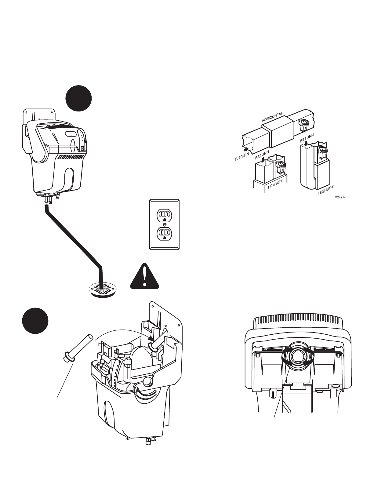
The preferred installation location is on the warm or supply side of the furnace. If that location is
not possible, the steam nozzle should be inserted a minimum of 12 in. upstream of the furnace filter.
Depending on the location and the duct rigidity, additional duct reinforcement may be necessary.
• Donotinstallthehumidifierwheretheambienttemperatureislowerthan32°F(0°C)orhigher
than 120°F (49°C).
• Donotinstallthehumidifierthroughsidewallsofareturnairductmadeofwood(e.g.,floor
joist).
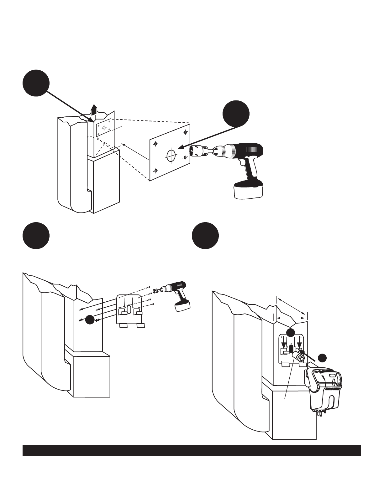
• Themountingareamustbestrongenoughtosupportthehumidifier’sweightwhenitisfull
of water (approximately 12 to 15 lbs.), and to hold the humidifier in a level position for safe,
reliable operation. Otherwise, additional duct or wall reinforcement will be necessary.
• Iftheductinghasexposedinsulatedmaterialsontheinterior,ensurethenozzleextends
beyondtheinsulationbyclearingawayexcessinsulationattheinsertionpoint.Youmaywish
to replace a section of insulated duct (approximately 6 in. x 6 in.) with rigid, non-insulated
sheet metal to ensure effective installation.
• Mounttheunitwhereitwillhavesmoothairflowacrosstheendofthesteamnozzle.
• Allowatleast1footclearancetoventilationholesinhumidifier’scover.Donotcoverthese
holes. Covering them can increase the internal operating temperature of the humidifier and
shorten the humidifier’s life.
• Allowatleast4inchesofclearancebetweenthesteamnozzleinsertionholeandthetopof
the interior duct to avoid condensation forming. The mounting template is designed to allow
clearance if the top of the template is at or below the top surface of the interior duct.
• Donotmountdirectlytoductboard.
• Donotinstallincompletelyenclosedspaces,suchasacabinetorunventilatedcloset.
Choose a location that is well ventilated.
Warning: Electrocution, Heavy Equipment, and Chemical Hazard.
Can cause death, blindness, water damage to home and heating element failure.
Warning: Steam Condensation, Fire, and Freezing Water Hazard.
Can cause failure of fan or limit control or result in water damage to home.

Humidification System
5 69-2307—01
safeTy PReCauTIons
M24744
duCT mounT InsTallaTIon
Choose a location that has access to a:
• Drainallowingaslopeof1/4in.
per foot of drain hose.
• Coldwaterline.
• Electricalcircuitratedtoyour
humidifier.
• Verticalsurfacewithadequate
clearances.
1
Model
Required Minimum
Circuit Capacity
RXIH-AS06A 7 Amps
RXIH-AS09A 10 Amps
RXIH-AS12A 12 Amps
M24745
Install duct nozzle.
2
M24746
Ensureo-ringgasket
is properly seated in
the groove.
M24894
Insert nozzle and twist clock-
wise to ensure tight seal of
nozzle to the humidifier.
Continuous
downslope
If installing the humidifier directly to the supply duct, follow steps on pages 5–6 and 14–18.
If mounting remote from the duct, follow steps on pages 7–18.
Draining water
may be hot.
Ensuredrainout-
let not exposed.
CAUTION
Hot water temperature above 120°F (49°C)
can cause burns from scalding.

Installation Guide
69-2307—01 6
duCT mounT InsTallaTIon
A) Slide foam gasket over nozzle and
insert the nozzle into duct hole
(pictured).
B) Push down to secure humidifier to
bracketarms.Ensuregasketforms
tight seal in duct hole.
Secure bracket to duct using #8
self-drilling sheet metal screws (4).
M24749
5 6
Proceed to page 14 for plumbing and wiring instructions.
M24750
A
B
Foam
gasket
M24748
SUPPLY
12 INCHES
4Drill 1-3/4-in. hole.
Position template sticker on supply duct. For tall coils that do not have this
clearance available, refer to remote mounting instructions.
3
Allow 3 in. clear-
ance from nozzle
outlet to duct wall.

Humidification System
7 69-2307—01
M24896A
Funnel or floor drain. Refer to governing
codes for drain pipe size and maximum
temperature requirements.
6 in.
8 in.
Most operation problems are caused
by improper hose installation. Always
ensure an uphill flow when installing
the remote hose, and avoid kinks,
sharp turns, or low spots that could
restrict the flow of steam into the
injection nozzle or condensation back
into the humidifier.
If the remote hose cannot be installed
with an upward pitch of 2 in./ft., a
wetted drip tee must be installed.
Failure to do so can result in back
pressure on the humidifier, which can
lead to duct nozzle water spitting or
leaking gasket. Remote hose must be
supported to prevent sagging or low
spots.
1
Choose a location for the humidifier and the
remote duct nozzle (see remote installs on
page 8).
It should have access for:
• Remotehoseinstallation.Steamhose
must be installed with 2 in./ft. pitch on a
continuous uphill slope.
• Drain.Allowacontinuousdownslopetothe
drain.
• Coldwaterline.
• Electricalcircuitratedtoyourhumidifier
(see circuit ratings on page 10).
RemoTe mounT InsTallaTIon
Use for mounting to a location other than the supply duct.
Maximum 3 ft.
2 in./ft. uphill
1/2 in.
minimum
diameter
When remote mounting, also follow these critical
steps in sizing the proper humidifier:
The 6-gallon model can be remotely mounted up to
15 feet if insulating the steam distribution tube
The 9- and 12-gallon models can be remotely mount-
ed up to 20 feet.
Ensureatleast2in.perfootslopeifinstallingthe
remote hose horizontally.
duCT mounT InsTallaTIon
Water in
elbow

Installation Guide
69-2307—01 8
Note: If air handler location temperatures will drop
below freezing at any time, the humidifier must be
mounted in a conditioned space, running a remote
hose to the duct.
M24786
Living Area Remote Options
M24781
Furnace or Mechanical Room Remote
M24785
Garage Remote
M24936
Duct Mount Remote
PRoPeR hose InsTalls
Draining
water may
be hot.
Ensure
drain out-
let not
exposed.
CAUTION
Hot water temperature above 120°F (49°C)
can cause burns from scalding.

Humidification System
9 69-2307—01
2 IN. PER FT
2 IN. PER FT
2 IN. PER FT
2 IN. PER FT
20 FT MAX
P - TRAP
DRAIN
WITH TRAP 5 FT MAX
3 FT MAXIMUM
DRAIN
P - TRAP
IF NO SLOPE
10 FT MAX GENTLE BEND
OBSTRUCTION
SUPPORTED REMOTE HOSE
20 FT MAX
DRAIN
WETTED P - TRAP
NOTE: HEIGHT OF TRAP MUST BE GREATER
THAN THE DUCT STATIC PRESSURE
DRAIN
P - TRAP
IF NO SLOPE
TYPICAL INSTALLATION
WHEN HUMIDIFIER IS ABOVE
REMOTE NOZZLE
KINKED
SAG
NO SLOPE
NO SLOPE
M29028
UNDRAINED
ELBOW
NOTES:
• Minimumupwardslopeofhoseindirectionofsteamflowat2in.perfoot;
• Minimumdownwardslopeofhoseindirectionofsteamflowat3/4in.perfoot;
• Maximumlengthofremotesteamhoseis20ft.
• HeightofP-trapsmustbegreaterthantheductstaticpressure.(Typical3in.
will suffice.) P-trap must also be wetted (see page 7).
• Minimizesharpbendsandelbows.
PRoPeR hose InsTalls
AVOIDTHESEINSTALLATIONMISTAKES.
PRoPeR hose InsTalls

Installation Guide
69-2307—01 10
RemoTe mounT InsTallaTIon
M24744
M24745
M24764
Install hose adapter from Remote
MountKit.
2
Model Minimum Circuit Capacity
RXIH-AS06A 7 Amps
RXIH-AS09A 10 Amps
RXIH-AS12A 12 Amps
Continuous
downflow
M24765
Remote Mount Kit
(sold separately) Hose Adapter
Duct Nozzle
Hose Clamps
Remote Hose
M24894
Insert hose adapter and twist
clockwise to ensure tight seal
of nozzle to the humidifier.
Ensureo-ringgasketis
properly seated in the
groove.
Draining water
may be hot.
Ensuredrainout-
let not exposed.
CAUTION
Hot water temperature above 120°F (49°C)
can cause burns from scalding.
•50024917-001=TenFootInsulatedHoseKit
•50024917-002=TwentyFootInsulatedHoseKit

Humidification System
11 69-2307—01
M24766
Position template sticker on remote location.
Note: The humidifier will weigh 12–15 lbs. (+/- 2 lbs.)
with water, so if mounting onto drywall or plaster,
position one side over a wall stud.
3
4Insert wall anchors (4) into pilot holes and secure
bracket to location.
M24767A
Push down to secure the humidifier
to bracket arms.
5
M24768
RemoTe mounT InsTallaTIonRemoTe mounT InsTallaTIon

Installation Guide
69-2307—01 12
M24770
Cut a 1-3/4 in. diameter duct hole, install the provided
gasket, and slide the remote nozzle up into the duct.
Secure remote nozzle to duct using #8 self-drilling
sheet metal screws (4).
6
IMPORTANT:
Run hose continuously uphill. For horizontal runs,
ensure a slope of 2 in. uphill per foot. Secure hose
every horizontal foot using clamps (provided).
For long horizontal runs, support the hose by first
securing a length of 2 x 4 lumber, U-channel, or
angle iron with the appropriate slope. Then attach
the hose to the top of this support. If remote hose
requires downward pitch, refer to pages 7 and 9 for
instruction.
M24771
Run remote hose from
the humidifier to the duct
nozzle location. Up to 20
ft. of hose can be used.
7
If mounting remotely requires running
hose through structural barriers (ie.
wall or ceiling), cut at least a 2-1/8 in.
hole and slide hose through.
Seal off unconditioned space with a
grommet (not provided) or caulk.
8
Attach remote hose by sliding over the nozzle
and adapter. Secure both hose ends with
clamps (provided).
9
RemoTe mounT InsTallaTIon
Minimum 3 in. clearance
required from nozzle outlet to
duct wall.

Humidification System
13 69-2307—01
RemoTe mounT InsTallaTIon RemoTe mounT InsTallaTIon
To install clamps onto the insulated steam hose:
Cut a slit in the insulation half way around the house. Do not cut into the steam hose.
Insert the hose clamp into the slit and hook it onto the hose.
A
B
A
B

Installation Guide
69-2307—01 14
M24852
M24772
PlumbIng
AInsert 1/4-in. water line into filter. Apply modest pressure to ensure a tight fit.
10
BInsert 1/4-in. water line into back-flow valve. Apply modest pressure for a tight fit.
Water line tapping options. See instructions provided with the option you choose.
M27428
CD
1/4-in. water line
1/2-in.
drain tube
Enlargedview
T-fitting
To humidifier
Saddle valve (provided)
Piercing pin
Water supply line
To humidifier
Continuous
downslope
To water supply
Manual shutoff
valve (sold
separately)
Draining water may be
hot.Ensuredrainoutlet
notexposed.Ensure
drain or condensate
pump is rated for at
least 120°F water.
CAUTION
Hot water temperature above 120°F (49°C)
can cause burns from scalding.
Description Part Number
In-Line Water Filter (included)
(required for warranty)
50028044-001
Back-flow valve (included)
(required)
50030142-001
CConnect 1/2-in. drain tube. Secure drain tube to barbed fitting with hose clamp.
DShut off the water supply. Secure 1/4-in. copper or plastic water feed tube.
AB
Check all water line connections to ensure no leaks once the humidifier is operational.
1/4-in. copper
or plastic

Humidification System
15 69-2307—01
Loosen captive cover
screw. Slide cover out from
front.
11
M24754
WIRIng
CAUTION: Voltage Hazard.
Before wiring to HVAC terminals, disconnect HVAC
equipmentpower.Ensurehumidifierisnotpluggedin.
Low-Voltage Terminals
24V AC power for electronic humidistat.
HUM Low-voltage humidistat (or thermostat) terminals control
humidifier operation.
C, R Connects to HVAC system transformer terminals (or relay
transformer fan control R and C) to ensure HVAC power
is present before humidifying. This can be disabled by
changing DIP switch 4 (see page 18).
RT Connects to thermostat R terminal, which is normally
switched to call for fan.
GT, GT connects to thermostat G terminal. GF connects
to fan board G terminal. Thermostat G passes through
the normally-closed (NC) relay contacts to GF, allowing
fan activation. When the humidifier is ready to provide
humidity to the home, it will take control of the fan by
forcing power from RT to GF (if not already activated).
EXT Whena24-vacfanboardisnotusedtocontrolblower
(hydronic or cooling-only applications), this connection
withGFprovidesdry-contactclosureforfancalls.EXT/
GF may be wired to a low-voltage relay control center to
provide line-voltage fan control.
M24895
24V
24V
HUM
HUM
C
GT
R
RT
GF
EXT
GF
M24893
Route wires through the raised harness tabs and out the notch at
therearofthechassis.Ensurewiresaresecureanddonotinter-
fere with assembly of cover.
Tabs Notch
PlumbIng

Installation Guide
69-2307—01 16
WIRIng
12 Wire the humidifier according to the diagram that applies to your humidity
control.
Follow this diagram if using a mechanical
humidistat.
HVAC
RECOMMENDED
AIR FLOW
SWITCH (AFS)
MECHANICAL
HUMIDISTAT
HVAC
POWER
MASTER
THERMOSTAT
HUM
HUM
GYWRRc
GYWR C
HUMIDIFIER - INTERNAL
24V
24V
HUM
HUM
C
GT
R
RT
GF
EXT
M29029
Factory
installed
jumper
If AFS is used, ensure
DIP 5 is in ON position.
Follow this diagram to wire Automatic Digital
Humidistat for manual operation.
Set the digital humidistat ISU parameter 10 to 1, and
ISU 25 to 2.
A
For auto-operation: also wire W and G to thermostat
W and G.
B
HVAC
DIGITAL HUMIDISTAT
THERMOSTAT
HUM
HUM
R
C
GYWRRc
GYWRC
24V
24V
HUM
HUM
C
GT
R
RT
GF
EXT
RECOMMENDED
AIR FLOW
SWITCH (AFS)
M29030
HVAC
POWER
MASTER
HUMIDIFIER - INTERNAL
Factory
installed
jumper
If AFS is used, ensure DIP 5 is in ON position.
A
B
Follow this diagram if using a blower fan dedicated to the humidifier (a fan separate from the HVAC
equipment, as in hydronic or cooling-only applications).
24V
24V
HUM
HUM
C
GT
R
RT
GF
EXT
HUMIDISTAT
HUM
HUM
HAC
HAC
MECHANICAL
HUMIDISTAT
HUM
HUM
HAC
HAC
RECOMMENDED
AIR FLOW SWITCH
(AFS)
HUMIDIFIER - INTERNAL
HVAC
120 VAC
RELAY
RED
BLACK
L1
L2
120
VAC
AT120
RC
M29031
HVAC POWER MASTER
Remove Factory
installed jumper
(R/RT)
If AFS is used, ensure DIP 5
is in ON position.

Humidification System
17 69-2307—01
Slide the cover back into place and secure captive screw.
Turn on the water supply and plug in the humidifier.
13
The Press Reset light will blink when
power is applied.
Press/releasetheRESETbuttonto
ready the humidifier. If not pushed,
the humidifier will automatically move
to ready after five minutes.
14
POWER
HUMIDIFYING
CLEAN TANK
CALL SERVICE
PRESS RESET
PRESS EMPTY
RESET
EMPTY
SEE LABEL BELOW !
M24763
M24762
Confirm that the furnace blower turns on to circulate air. This will take about 10–15
minutes upon call for humidity.
16
Important for Remote Installation:
After the humidifier has produced steam for 10–15 minutes, check the integrity of the
remote hose to ensure no sags have occurred. Add or adjust clamps if necessary to
ensure 2 in. per foot continuous slope.
Turn the control to a high setpoint (60% +). Be sure to turn this back down when test-
ing is complete. “Off” will turn the humidifier off.
15
WIRIng WIRIng

Installation Guide
69-2307—01 18
dIP sWITCh seleCTIon
BetweenthetransformerandLEDdisplayonthecircuitboardaretwosetsofDIPswitches.DIP
1 and 2 can be configured to adjust cleaning cycles. DIP 4 and 5 can simplify wiring. DIP 3 and 6
are not used at this time. Details below.
M24853
OFF
ON
OFF
ON
OFF
ON
DIP 1
DIP 2
DIP 3
DIP 4
DIP 5
DIP 6
DIP 1
DIP 2
DIP 3
DIP 4
DIP 5
DIP 6
DIP 1
DIP 2
DIP 3
DIP 4
DIP 5
DIP 6
DIP
3
DIP
3
D
IP
3
D
IP
6
D
IP
6
DIP
6
Run time (hrs) End-of-Season timer
(hrs)
Clean tank indicator
10 hrs of humidify-
ing before system
auto-flushes debris
from tank.
48 hrs before system auto-
drains and remains empty
until next call for humidity.
1 year of total time (operational
and inactive) before the Press
Emptylightwillblink,indicating
it is time to manually clean the
water tank.
20 hrs of humidify-
ing before system
auto-flushes debris
from tank.
48 hrs before system auto-
drains and remains empty
until next call for humidity.
1 year of total time (operational
and inactive) before the Press
Emptylightwillblink,indicating
it is time to manually clean the
water tank.
30 hrs of humidify-
ing before system
auto-flushes debris
from tank.
48 hrs before system auto-
drains and remains empty
until next call for humidity.
1 year of total time (operational
and inactive) before the Press
Emptylightwillblink,indicating
it is time to manually clean the
water tank.
M28181
DIP 1
DIP 2
DIP 3
DIP 4
DIP 5
DIP 6
DIP 1
DIP 2
DIP 3
DIP 4
DIP 5
DIP 6
OFF
ON
OFF
ON
DIP 1
DIP 2
DIP 3
DIP 4
DIP 5
DIP 6
OFF
ON
DIP
3
D
IP
3
DIP
3
D
IP
6
DIP
6
D
IP
6
DIP 4 OFF, DIP 5 ON: If the humidifier determines that no airflow*
is present two minutes after the blower fan call, it will shut down
steam output and activate a service light.
*Requires installation of air flow switch. See 'Wiring' section for details.
DIP 4 ON, DIP 5 either setting: The humidifier will allow humidity
without HVAC power present and without airflow.
DIP 4 OFF, DIP 5 OFF: The humidifier will not be allowed to humidify
without HVAC power being present.
This manual suits for next models
2
Table of contents
Other Rheem Humidifier manuals