manuals.online logo
Brands
  1. Home
  2. •
  3. Brands
  4. •
  5. Rheem
  6. •
  7. Water Heater
  8. •
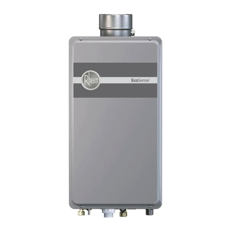
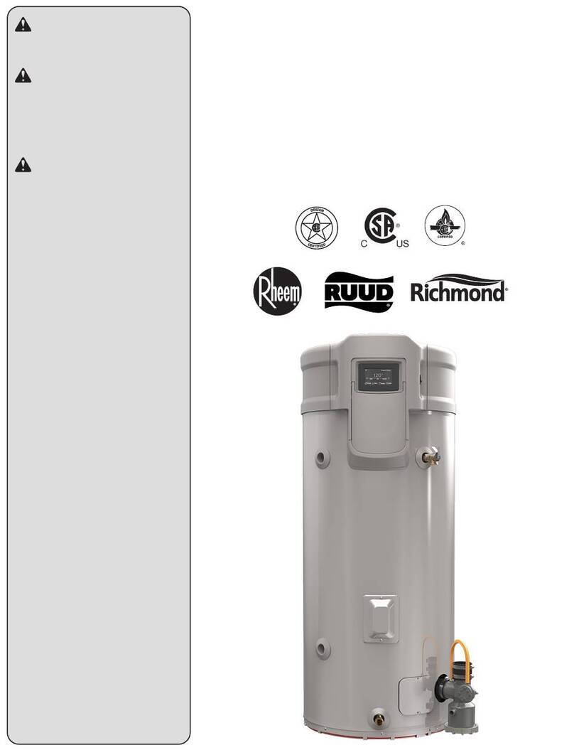
  9. Rheem PowerVent Commercial Gas Water Heater Reference manual

Rheem PowerVent Commercial Gas Water Heater Reference manual

Other manuals for PowerVent Commercial Gas Water Heater

2

Other Rheem Water Heater manuals

Rheem Universal GD100-250 User manual

Rheem

Rheem Universal GD100-250 User manual

Rheem VentMaster GP100-150 User manual

Rheem

Rheem VentMaster GP100-150 User manual

Rheem RTG-53X User manual

Rheem

Rheem RTG-53X User manual

Rheem GHE119SS User manual

Rheem

Rheem GHE119SS User manual

Rheem RUTG 64DV Programming manual

Rheem

Rheem RUTG 64DV Programming manual

Rheem PRO415TM User manual

Rheem

Rheem PRO415TM User manual

Rheem 27 Technical Document

Rheem

Rheem 27 Technical Document

Rheem RUUD AdvantagePlus Operating instructions

Rheem

Rheem RUUD AdvantagePlus Operating instructions

Rheem 60 User manual

Rheem

Rheem 60 User manual

Rheem MHD85245 User manual

Rheem

Rheem MHD85245 User manual

Rheem GG Series User manual

Rheem

Rheem GG Series User manual

Rheem Stellar 50L Technical Document

Rheem

Rheem Stellar 50L Technical Document

Rheem 27 874 Series Technical Document
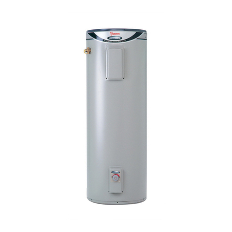
Rheem

Rheem 27 874 Series Technical Document

Rheem Gladiator User manual

Rheem

Rheem Gladiator User manual

Rheem Loline 271 Technical Document

Rheem

Rheem Loline 271 Technical Document

Rheem 613050 Operating instructions

Rheem

Rheem 613050 Operating instructions

Rheem Multipak MPE02 Technical Document

Rheem

Rheem Multipak MPE02 Technical Document

Rheem RTGH-RH10DV User manual

Rheem

Rheem RTGH-RH10DV User manual

Rheem PowerVent Commercial Gas Water Heater User manual

Rheem

Rheem PowerVent Commercial Gas Water Heater User manual

Rheem GHE80SS User manual

Rheem

Rheem GHE80SS User manual

Rheem 441 Series Technical Document

Rheem

Rheem 441 Series Technical Document

Rheem RETEX-04T User manual

Rheem

Rheem RETEX-04T User manual

Rheem PROG50-38N RH60 User manual

Rheem

Rheem PROG50-38N RH60 User manual

Rheem 265 series User manual

Rheem

Rheem 265 series User manual

Popular Water Heater manuals by other brands

clage German pool CEX13 operating instructions

clage

clage German pool CEX13 operating instructions

Noritz proTough NR98SV installation manual

Noritz

Noritz proTough NR98SV installation manual

DeDietrich KALIKO TWH 200 EV Installation and service manual

DeDietrich

DeDietrich KALIKO TWH 200 EV Installation and service manual

veito FLOW Installation and operating instructions

veito

veito FLOW Installation and operating instructions

ICI Caldaie COSMOGAS AGUATANK 150 Instructions for installation, use and maintenance manual

ICI Caldaie

ICI Caldaie COSMOGAS AGUATANK 150 Instructions for installation, use and maintenance manual

Savio Laser 11 A Instruction manual for installation and use

Savio

Savio Laser 11 A Instruction manual for installation and use

Kenmore 153.582400 Use & care guide

Kenmore

Kenmore 153.582400 Use & care guide

STIEBEL ELTRON Eltronom SHU 5 S Operating and installation instructions

STIEBEL ELTRON

STIEBEL ELTRON Eltronom SHU 5 S Operating and installation instructions

clage E-Mini Series Operating and installation instructions

clage

clage E-Mini Series Operating and installation instructions

Solar SunX 317365-002 instruction manual

Solar

Solar SunX 317365-002 instruction manual

Bradford White EF Series Service manual

Bradford White

Bradford White EF Series Service manual

Dimplex ECSd125-580 Installation and user instructions

Dimplex

Dimplex ECSd125-580 Installation and user instructions

Dux 32FCR6N installation manual

Dux

Dux 32FCR6N installation manual

Noritz N-132M Owner's guide and installation manual

Noritz

Noritz N-132M Owner's guide and installation manual

TESY GCV7/4S 10047 Instructions for use and maintenance

TESY

TESY GCV7/4S 10047 Instructions for use and maintenance

A.O. Smith Gphe 50 instruction manual

A.O. Smith

A.O. Smith Gphe 50 instruction manual

Rinnai REP199i Installation and operation manual

Rinnai

Rinnai REP199i Installation and operation manual

Toyotomi Oil Miser OM-148 (Type D) Operation and maintenance instructions

Toyotomi

Toyotomi Oil Miser OM-148 (Type D) Operation and maintenance instructions

manuals.online logo
manuals.online logoBrands
  • About & Mission
  • Contact us
  • Privacy Policy
  • Terms and Conditions

Copyright 2025 Manuals.Online. All Rights Reserved.

S
1626.docx
S
EQUENC
E
This is a
display.
T
Commu
n
port po
w
heater se
codes, a
n
temperat
u
codes).
U
heater.
The user
interacti
o
The disp
l
thermost
Tank is
f
Gas sup
p
Unit is p
l
prong pl
u
VAC.
Turn roc
k
blower t
o
Slide ga
s
the ON
p
Each ti
m
powered
random
a
(RAM),
t
and the
n
memory
Po
w
E
OF
O
PER
A
power vent
T
he word ‘c
n
ication bet
w
w
ered by a 2
4
t point, wat
e
n
d diagnosti
c
u
re, availab
l
U
ser displa
y
display has
o
n with the
d
l
ay is conne
c
at wire with
f
ull of water
.
p
ly is conne
c
l
ugged into
a
u
g wall soc
k
k
er switch
o
o
ON positi
o
s
control val
v
p
osition.
m
e the contro
up they tes
t
a
ccess mem
o
t
he progra
m
n
on-volatile
(EEPROM)
TEC
H
w
erVent wi
t
A
TIONS
water heate
r
ontrol’ in th
w
een the co
n
4
V transfor
m
e
r heater mo
c
s. Outputs
l
e hot water
,
y
will be pac
k
a backlight
d
isplay for a
c
ted to the
w
a maximu
m
.
c
ted.
a
3-
k
et 120
o
n the
o
n.
v
e to
ls are
t
the
o
ry
code
.
H
NICAL S
E
Technica
l
1-8
0
t
h Electron
i
r
control tha
t
is sequence
n
trol and the
m
er. Inputs
i
de of operat
include stat
u
,
diagnostic
s
k
aged with
t
that comes
o
minimum
o
w
ater heate
r
w
m
length of 1
Fill tank.
Connect ga
natural; an
d
Electrical s
o
wired pola
r
an earth gr
o
to brass scr
silver scre
w
ground.
Blower mo
t
controls all
b
lower mo
t
display.
At power
O
for heat, th
e
a self-test
d
If the self-
c
control loc
k
indications
and user di
s
E
RVICE D
E
l
Service B
u
0
0-432-837
3
i
c Control
S
t
provides t
w
will refer to
user displa
y
i
nclude wat
e
ion, error
u
s (mode,
s
and error
t
he water
o
n during
o
f 8 seconds.
w
ith 3-wire
00 feet.
s at 7” w.c
f
d
10” w.c. f
o
o
cket must
b
r
ity correct
w
o
un
d
. Black
e
w; white
w
w
; green wir
e
t
or
r
ocker s
w
power inpu
t
t
o
r
, gas valv
e
O
N and a de
m
e
control pe
r
d
iagnostic ro
u
c
heck fails, t
h
k
s out with
on the cont
r
s
play.
E
PARTME
N
u
lletin
3
S
equence of
w
o way co
m
the gas co
n
y
is achieve
d
e
r
.
f
or
o
r LP.
b
e
w
ith
wire
w
ire to
e
to
w
itch
t
s to
e
and
m
and
r
forms
utine.
h
e
r
ol
N
T
Operation
s
m
munication
s
n
trol valve.
d
through a
c
s
1
s
to a wired
u
c
ommunicat
i
u
ser
i
ons
1626.docx
“Unlock
”
pressing
arrow ke
temperat
u
exceed 1
Call for
H
Control
c
things:
1.
A
t
h
s
w
2.
A
E
s
w
The con
t
sequenc
e
entering
The har
d
require
a
cycle of
t
the hard
120V po
w
the cont
r
motor o
n
the gas c
Note: Pr
i
control i
s
b
etween
wires on
molex.
Po
w
”
the displa
y
the UP and
D
ys. Set the
w
u
re setting
n
20
0
F.
H
eat –
c
hecks for t
w
A
closed blo
w
h
ermal over
w
itch and…
A
n OPEN
E
XHAUST
p
w
itch
rol will atte
m
e
5 times be
f
into a hard
l
d
lockout wi
l
manual po
w
t
he control t
l
ockout.
w
er is passe
r
ol to the bl
o
n
the yellow
ontrol.
i
mary powe
r
s
120 VAC
the black a
n
the four po
s
TEC
H
w
erVent wi
t
y
by
D
OWN
w
ater
n
ot to
w
o
w
er
temp
.
p
ressure
m
pt this
f
ore
l
ockout.
l
l
w
er
o clear
d from
wer
wire on
r
to the
n
d white
s
ition
H
NICAL S
E
Technica
l
1-8
0
t
h Electron
i
Temperatu
r
electronica
l
Thermisto
r
bulb.
Heat icon
d
The norma
l
thermal sw
i
series
b
efo
r
switch.
If the vent
t
@180
0
F, t
h
switch will
thermal sw
i
will get an
e
In normal
o
pressure s
w
the start of
You will h
e
running.
E
RVICE D
E
l
Service B
u
0
0-432-837
3
i
c Control
S
r
e is sensed
l
ly by the
r
in the sens
i
d
isplay is on
l
ly closed
b
l
o
i
tch is wire
d
r
e the press
u
t
emp excee
d
h
en the ove
r
-
activate. IF
i
tch is OPE
N
e
rror code.
o
peration, th
e
w
itch is OPE
N
call for heat
e
a
r
the blow
e
E
PARTME
N
u
lletin
3
S
equence of
i
ng
.
owe
r
d
in
u
re
d
s
-
temp
the
N
, you
e
N
at
t
.
e
r
N
T
Operation
s
s
2
1626.docx
With the
the press
close.
The con
t
jumping
switch f
o
Pre-purg
seconds.
The con
t
sequenc
e
entering
A signal
pressure
control
v
(IF blow
e
pressure
Ignition
a
Po
w
blower run
n
ure switch
w
rol logic pr
e
this pressur
e
o
r main bur
n
e may last
u
rol will atte
m
e
5 times be
f
into a hard
l
is passed th
r
switch to th
e
v
alve.
e
r, venting,
&
switch are
a
a
ttempt
TEC
H
w
erVent wi
t
n
ing,
w
ill
e
vents
e
n
er.
p
to 30
m
pt this
f
ore
l
ockout.
r
u the
e
&
a
ll OK.)
H
NICAL S
E
Technica
l
1-8
0
t
h Electron
i
IF the exha
u
venting cre
a
b
ack press
u
b
lockage, t
h
switch will
inducing a
f
Exhaust pr
e
Breaks on
p
-.45 ± .05 i
n
The hard l
o
a manual p
o
control to c
lockout
This is the
s
energize th
e
igniter is e
n
valve is en
e
immediatel
y
begins.
Visually v
e
sparking in
s
combustio
n
Pilot flame
immediatel
y
E
RVICE D
E
l
Service B
u
0
0-432-837
3
i
c Control
S
u
st side of t
h
a
tes too mu
c
u
re due to
h
e pressure
not close
f
ault.
e
ssure switc
h
p
ressure fall
;
n
w.c.
o
ckout will r
e
o
wer cycle
o
lear the har
d
s
ignal need
e
e
igniter. T
h
n
ergized an
d
e
rgized
y
after the s
p
e
rify the igni
s
ide the
n
chambe
r
.
and main b
u
y
follow.
E
PARTME
N
u
lletin
3
S
equence of
h
e
c
h
h
:
;
e
quire
o
f the
d
e
d to
h
e
d
pilot
p
ark
i
ter is
u
rner
N
T
Operation
s
s
3
1626.docx
Flame is
There is
rectifica
t
while th
e
operatin
g
If flame
i
the Trial
turns off
,
closes, t
h
inducer
t
then tur
n
and ente
r
flashes t
h
error co
d
Water h
e
setting.
Blower
m
safety s
w
venting
t
Flamma
b
sensor is
Water is
Control
s
to the ga
s
Blower
c
purge to
and com
b
Unit is i
n
Po
w
rectified.
always a fla
m
t
ion circuit
c
e
main burn
e
g
.
i
s not sense
d
period, the
i
,
the pilot v
a
h
e control r
u
hrough Pos
t
n
s off the in
d
r
s Soft Loc
k
h
e Soft Loc
k
d
e.
e
ats to ther
m
m
otor therm
a
w
itch is mon
i
emperature
s
b
le Vapor (
F
monitoring
.
heated.
s
huts off all
p
s
valve.
c
ontinues a
p
vent excess
b
ustion gas
e
n
stan
d
-
b
y
m
TEC
H
w
erVent wi
t
m
e
heck
e
r is
d
during
i
gniter
a
lve
u
ns the
t
-purge
d
ucer
k
out and
k
out
m
ostat
a
l
i
toring
s
.
F
V)
.
p
ower
p
ost
heat
e
s.
m
ode.
H
NICAL S
E
Technica
l
1-8
0
t
h Electron
i
After flam
e
recognized
igniter will
IF the mai
n
during heat
recycle an
d
The contro
l
Lockout fo
r
automatica
l
the Deman
d
Control wi
l
times, then
Lockout.
ECO is mo
n
temperatur
e
Blower mo
t
switch trip
s
automatic r
FV Sensor
i
local envir
o
presence o
f
vapors
In stand-
b
y
control con
the water t
e
thermistor
t
water insid
e
within the
u
range.
Safeties m
o
health, oth
e
and the loc
a
for flamma
b
E
RVICE D
E
l
Service B
u
0
0-432-837
3
i
c Control
S
e
has been
(rectified),
t
turn off.
n
burner fail
s
ing, the uni
t
d
attempt ig
n
l
remains in
r
5 minutes
b
l
ly respondi
n
d
for Heat.
l
l cycle thre
e
go into a H
a
n
itoring wat
e
. Trips at 1
9
t
or thermal
s
s
at 180°F w
eset at 125°
F
i
s monitori
n
o
nment for
f
flammable
mode, the
g
stantly mon
i
e
mperature
v
t
o ensure th
e
e
the tank is
u
se
r
-selecte
d
o
nitors contr
er
fault cond
i
a
l environm
e
b
le vapors.
E
PARTME
N
u
lletin
3
S
equence of
t
he
s
t
will
n
ition.
Soft
b
efore
n
g to
e
a
rd
t
er
9
9°F.
s
afety
w
ith
F
.
n
g
g
as
i
tors
v
ia the
e
d
r
ol
d
itions
e
nt
N
T
Operation
s
s
4