3
The Rhino®Multi-Pro™gas powered
driver is designed to drive fence post,
ground rod, delineator post, vineyard post,
form pin, tent stake and other like items
into the ground.
Uses, other than those
intended, can result
in injury to the operator as well as those
around the operator. Damage to the driver
and to the surrounding area may result
as well. This post driver is intended for
use by professional installers. Never allow
children to operate this tool.
Most accidents can be prevented if you
follow all instructions in this manual and
on the post driver. The most common haz-
ards are discussed below, along with the
best method to protect yourself and others.
UNDERGROUND
UTILITIES: Driving
a post into an underground utility can be
EXTREMELY DANGEROUS, exposing
the operator and those around to poten-
tially life threatening danger. Damage to
surrounding property can also occur as a
result of a post being driven into an under-
ground utility. Be absolutely certain that
you are aware of all underground utilities
in the area in which you intend to drive
posts. Ensure that a certied locating ser-
vice has identied all underground utilities
prior to beginning your project. Failure to
do so can be catastrophic. Underground
utilities include but are not limited to:
Electric, Gas, Telephone, Water, Sewer,
TV Cable, Lawn Sprinklers, etc.
GASOLINE: Gasoline
is HIGHLY
FLAMMABLE and EXPLOSIVE. You
can be burned or seriously injured when
handling fuel.
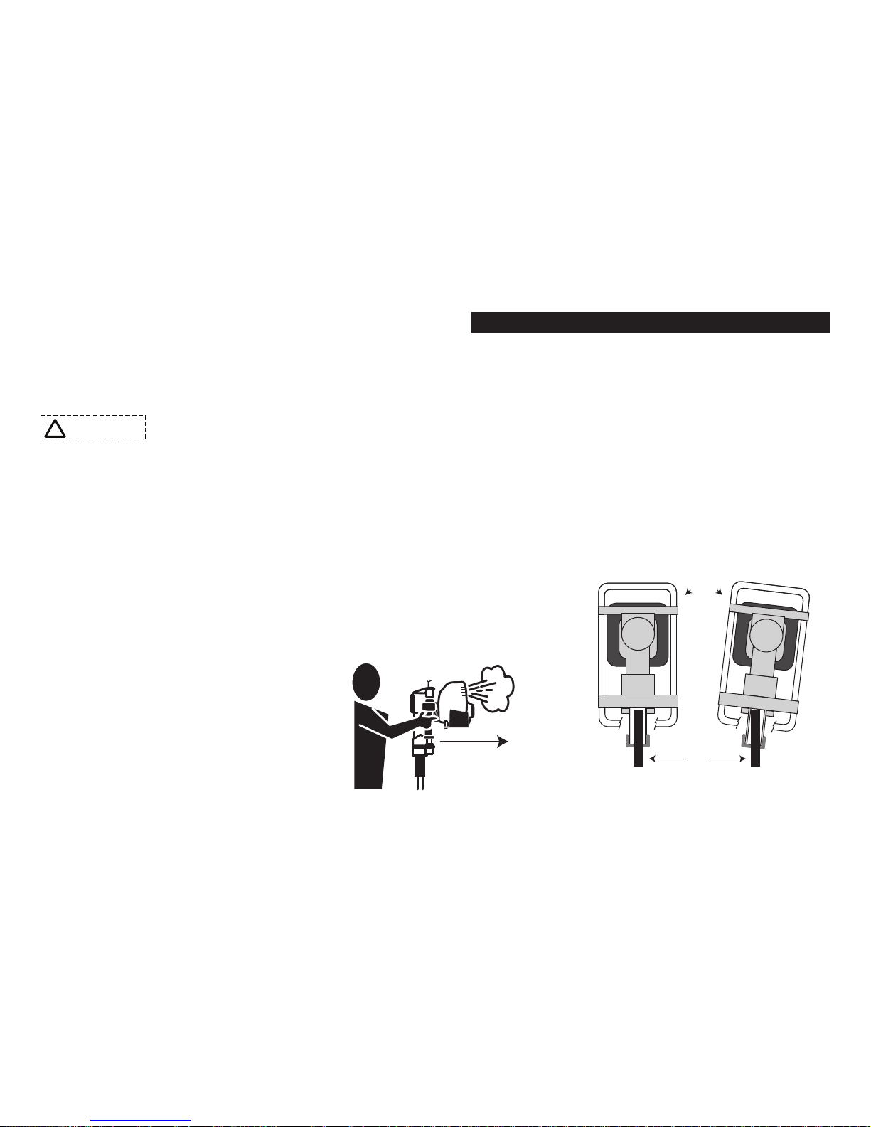
EXHAUST: The ex-
haust from the engine
contains poisonous carbon monoxide gas
that can build up to dangerous levels in
closed areas. Breathing carbon monoxide
can cause unconsciousness or death. Never
run the engine in a closed or even partly
closed area where people may be present.
The engine exhaust
from this product contains chemicals
known to the State of California to cause
cancer, birth defects or other reproductive
harm.
ENGINE
MAINTENANCE:
Improperly maintaining the engine on this
power tool, or failure to correct a problem
before operation, can cause a malfunc-
tion in which you can be seriously hurt
or killed. In accordance with the engine
owner’s manual, always perform a pre-
operation inspection of the engine before
each use and correct any problem.
DRIVER
MAINTENANCE:
Improperly maintaining the driving
mechanism on this power tool, or failure
to correct a problem before operation, can
cause a malfunction in which you can be
seriously hurt or killed.
In accordance with this manual, always
perform a pre-operation inspection of the
driving mechanism before each use and
correct any problem.
IMPORTANT SAFETY INFORMATION
POST DRIVER SAFETY
!WARNING