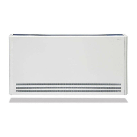
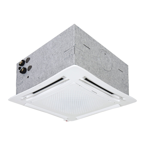
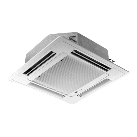
RHOSS Yardy EV3 User manual

Yardy EV3 | YardyDUCT2
IT | Motore AC - Ventilconvettori a pavimento e softto e canalizzabili.
Yardy EV3: Ventilconvettori con mantello e da incasso.
YardyDUCT2: Ventilconvettori canalizzabili.
EN | AC motor - Floor or ceiling ducted fan coils.
Yardy EV3: Fan coils with casing and for built-in installation.
YardyDUCT2: - Ducted fan coils.
FR | Moteur AC - Ventilo-convecteurs au sol et au plafond et
gainables.
Yardy EV3: Ventilo-convecteurs carrossés et encastrables.
YardyDUCT2: Ventilo-convecteurs gainables.
DE | Motor AC - Gebläsekonvektoren Stand-und Deckenmontage
und kanalisierbar.
Yardy EV3: Gebläsekonvektor mit Gehäuse und Einbau-
Ausführung.
YardyDUCT2: - Kanalisierbare Gebläsekonvektoren.
ES | Motor AC - Fan coils de piso y techo y canalizables.
Yardy EV3: Fan coils con camisa y empotrables.
YardyDUCT2: - Fan coils canalizables.
Yardy-I EV3 | Yardy-ID2
IT | Motore brushless EC - Ventilconvettori a pavimento e softto e
canalizzabili.
Yardy-I EV3: Ventilconvettori con mantello e da incasso.
Yardy-ID2: Ventilconvettori canalizzabili.
EN | EC brushless motor - Floor or ceiling ducted fan coils.
Yardy-I EV3: Fan coils with casing and for built-in installation.
Yardy-ID2: Ducted fan coils.
FR | Moteur brushless EC - Ventilo-convecteurs au sol et au plafond
et gainables.
Yardy-I EV3: Ventilo-convecteurs carrossés et encastrables.
Yardy-ID2: Ventilo-convecteurs gainables.
DE | Brushless-Motor EC - Gebläsekonvektoren Stand-und
Deckenmontage und kanalisierbar.
Yardy-I EV3: Gebläsekonvektor mit Gehäuse und Einbau-
Ausführung.
Yardy-ID2: Kanalisierbare Gebläsekonvektoren.
ES | Motor brushless EC - Fan coils de piso y techo y canalizables.
Yardy-I EV3: Fan coils con camisa y empotrables.
Yardy-ID2: Fan coils canalizables.
INSTRUCTIONS FOR USE
H58046/D

Dichiarazione di conformità
La società RHOSS S.p.A.
con sede ad Arquà Polesine (RO), via delle Industrie 211, dichiara,
sotto la propria esclusiva responsabilità, che i prodotti della serie
Yardy EV3 - YardyDUCT2 - Yardy-I EV3 - Yardy-ID2
sono conformi ai requisiti essenziali di sicurezza di cui alla Direttiva
Macchine 2006/42/CE.
------------
La macchina è inoltre conforme alle seguenti direttive:
- 2014/35/UE (Bassa Tensione).
- 2014/30/UE (Compatibilità Elettromagnetica).
- Regolamento n.327/2011/UE in attuazione alla Direttiva 2009/125/CE
ERP
- Direttiva restrizione d’uso di talune sostanze pericolose nelle
attrezzature elettriche ed elettroniche 2011/65/EU
Statement of conformity
RHOSS S.p.A.
located in Arquà Polesine (RO), via delle Industrie 211, hereby states on its
own exclusive responsibility that the products in the
Yardy EV3 - YardyDUCT2 - Yardy-I EV3 - Yardy-ID2
are compliant with the essential safety requirements as set forth in Machine
Directive 2006/42/CE.
------------
The machine is also compliant with the following directives:
- 2014/35/UE (Low Voltage).
- 2014/30/UE (Electromagnetic Compatibility).
- Regulation n.327/2011/UE implementing Directive 2009/125/EC ERP
- Restriction of the use of certain hazardous substances in electrical and
electronic equipment 2011/65/EU
Déclaration de conformité
La société RHOSS S.p.A.
dont le siège se trouve à Arquà Polesine (RO), via delle Industrie 211,
déclare, sous sa responsabilité exclusive, que les produits de la série
Yardy EV3 - YardyDUCT2 - Yardy-I EV3 - Yardy-ID2
sont conformes aux caractéristiques de sécurité requises par la
Directive Machines 2006/42/CE.
------------
L’appareil est par ailleurs conforme aux directives suivantes :
- 2014/35/UE (Basse Tension).
- 2014/30/UE (Compatibilité Electromagnétique).
- Règlement n° 327/2011/UE de mise en oeuvre de la Directive
2009/125/CE ERP
- Dorective restriction de l’utilisation de certaines substances
dangereuses dans les équipements électriques et électroniques
2011/65/EU
Konformitätserklärung
Der Hersteller RHOSS S.p.A.
mit Geschäftssitz in Arquà Polesine (RO), via delle Industrie 211, erklärt
eigenverantwortlich, dass die Geräte der Baureihe
Yardy EV3 - YardyDUCT2 - Yardy-I EV3 - Yardy-ID2
den grundsätzlichen Anforderungen an die Sicherheit in Übereinstimmung
mit der Maschinenrichtlinie 2006/42/EG entsprechen.
------------
Darüber hinaus entspricht die Maschine folgenden Richtlinien:
- 2014/35/UE, (Nieder Spannung).
- 2014/30/UE (Elektromagnetische Verträglichkeit).
- Verordnungen EU 327/2011 zur Umsetzung der Richtlinie 2009/125/EG
ERP
- Beschränkung der Verwendung bestimmter gefährlicher Stoffe in Elektro-
und Elektronikgeräten 2011/65/EU
Declaración de conformidad
La empresa RHOSS S.p.A.
con sede en Arquà Polesine (RO), via delle Industrie 211, declara bajo
su única responsabilidad que los productos de la serie
Yardy EV3 - YardyDUCT2 - Yardy-I EV3 - Yardy-ID2
Se encuentran en conformidad con los principales requisitos de
seguridad indicados en la Directiva de máquinas 2006/42/CE.
------------
La máquina, además, se encuentra en conformidad con las siguientes
directivas:
- 2014/35/UE, (Baja Tensòn).
- 2014/30/UE (Compatibilidad electromagnética).
- Reglamento n.327/2011/UE en cumplimiento de la Directiva
2009/125/CE ERP
- Directiva restricción a la utilización de determinadas sustancias
peligrosas en aparatos eléctricos y electrónicos 2011/65/EU
Codroipo, lì 20 giugno 2016 Responsabile progettazione / Responsible planning / Responsable
de la conception / Responsible Design / Responsable de diseño
Michele Albieri

3
Sezione I :: Utente IT
Italiano
I. SEZIONE I: UTENTE.................................................................4
Descrizione della macchina .................................................4
Condizioni di utilizzo previste...............................................4
,GHQWL¿FD]LRQHGHOODPDFFKLQD .............................................4
Versioni ................................................................................4
Limiti di funzionamento ........................................................4
Informazioni sugli usi non consentiti ....................................4
Rischi residui e pericoli che non possono essere eliminati..4
Istruzioni di utilizzazione ......................................................4
Pulizia dell’unità ...................................................................5
Avvertenze e suggerimenti...................................................5
II. SEZIONE II: INSTALLAZIONE E MANUTENZIONE................6
Istruzioni di trasporto............................................................6
Istruzioni di installazione......................................................6
Istruzioni per l’avviamento....................................................8
Istruzioni di manutenzione ...................................................8
SIMBOLOGIA UTILIZZATA
RIFERIMENTI NORMATIVI
UNI EN 292 Sicurezza del macchinario. Concetti fondamentali, principi generali di
progettazione
UNI EN 294 Sicurezza del macchinario. Distanze di sicurezza per impedire il
raggiungimento di zone pericolose con gli arti superiori.
UNI EN 563 6LFXUH]]DGHOPDFFKLQDULR7HPSHUDWXUHGHOOHVXSHU¿FLGLFRQWDWWR'DWL
HUJRQRPLFLSHUVWDELOLUHLYDORULOLPLWLGLWHPSHUDWXUDSHUVXSHU¿FLFDOGH
UNI EN 1050 Sicurezza del macchinario. Principi per la valutazione del rischio.
UNI 10893 Documentazione tecnica di prodotto. Istruzioni per l’uso
EN 13133 Brazing. Brazer approval
EN 12797 Brazing. Destructive tests of brazed joints
EN 378-1 Refrigeration systems and heat pumps – safety and environmental
UHTXLUHPHQWV%DVLFUHTXLUHPHQWVGH¿QLWLRQVFODVVL¿FDWLRQDQG
selection criteria
PrEN 378-2 Refrigeration systems and heat pumps – safety and environmental
requirements. Design, construction, testing, installing, marking and
documentation
CEI EN 60335-
2-40
Sicurezza degli apparecchi elettrici d’uso domestico e similare. Parte
2: Norme particolari per le pompe di calore elettriche, per i condizio-
QDWRULG¶DULDHSHULGHXPLGL¿FDWRUL
UNI EN ISO 3744 Determinazione dei livelli di potenza sonora delle sorgenti di rumore
mediante pressione sonora. Metodo tecnico progettuale in un campo
HVVHQ]LDOPHQWHOLEHURVXXQSLDQRULÀHWWHQWH
EN 50081-1:1992 Electromagnetic compatibility - Generic emission standard Part 1:
Residential, commercial and light industry
Simbolo 6LJQL¿FDWR
!
L’indicazione PERICOLO GENERICO è usata per informare
l’operatore ed il personale addetto alla manutenzione di rischi
FKHSRVVRQRFRPSRUWDUHODPRUWHGDQQL¿VLFLPDODWWLHLQTXDO-
sivoglia forma immediata o latente.
L’indicazione PERICOLO COMPONENTI IN TENSIONE è
usata per informare l’operatore ed il personale addetto alla
manutenzione circa i rischi dovuti alla presenza di tensione.
L’indicazione PERICOLO SUPERFICI TAGLIENTI è usata per
informare l’operatore ed il personale addetto alla manutenzio-
QHGHOODSUHVHQ]DGLVXSHU¿FLSRWHQ]LDOPHQWHSHULFRORVH
L’indicazione PERICOLO SUPERFICI CALDE è usata per in-
formare l’operatore ed il personale addetto alla manutenzione
GHOODSUHVHQ]DGLVXSHU¿FLFDOGHSRWHQ]LDOPHQWHSHULFRORVH
L’indicazione PERICOLO ORGANI IN MOVIMENTO è usata
per informare l’operatore ed il personale addetto alla manuten-
zione circa i rischi dovuti alla presenza di organi in movimento.
L’indicazione AVVERTENZE IMPORTANTI è usata per richia-
mare l’attenzione su azioni o pericoli che potrebbero creare
danni all’unità o ai suoi equipaggiamenti.
L’indicazione SALVAGUARDIA AMBIENTALE fornisce istru-
zioni per l’utilizzo della macchina nel rispetto dell’ambiente.
INDICE
Italiano.......................... 3
English.......................... 10
Français........................ 17
Deutsch ........................ 24
Espanol......................... 31
Le istruzioni originali della presente pubblicazione sono in lingua italiana, le altre lingue sono una traduzione delle istruzioni
originali.
E’ vietata la riproduzione la memorizzazione e la trasmissione anche parziale della presente pubblicazione, in qualsiasi
forma, senza la preventiva autorizzazione scritta della RHOSS S.p.A. I centri di assistenza tecnica della RHOSS S.p.A.
sono disponibili a risolvere qualunque dubbio inerente all’utilizzo dei suoi prodotti ove la manualistica fornita risulti non
soddisfacente. La RHOSS S.p.A. si ritiene libera di variare senza preavviso le caratteristiche dei propri prodotti. RHOSS
6S$ DWWXDQGR XQD SROLWLFD GL FRVWDQWH VYLOXSSR H PLJOLRUDPHQWR GHL SURSUL SURGRWWL VL ULVHUYD LO GLULWWR GL PRGL¿FDUH
VSHFL¿FKHHTXLSDJJLDPHQWLHGLVWUX]LRQLUHODWLYHDOO¶XVRHDOODPDQXWHQ]LRQHLQTXDOVLDVLPRPHQWRHVHQ]DDOFXQSUHDYYLVR
Italiano
ALLEGATI
Dimensionali.......................................................................38
Dimensioni e ingombri valvole............................................40
Schemi elettrici....................................................................43

4
Sezione I :: Utente
IT
I. SEZIONE I: UTENTE
DESCRIZIONE DELLA MACCHINA
Yardy sono ventilconvettori per il trattamento dell’aria in am-
bienti interni.
L’unità non é destinata all’installazione in locali ad uso lavande-
ria (norma CEI EN 60335-2-40).
CONDIZIONI DI UTILIZZO PREVISTE
!PERICOLO!
L’installazione della macchina è prevista solo all’interno in ambienti ad
uso domestico e similari.
PERICOLO!
E’ vietato introdurre oggetti attraverso le bocche di aspirazione e
mandata aria.
IMPORTANTE!
Il corretto funzionamento dell’unità è subordinato alla scrupolosa os-
servanza delle istruzioni d’uso, al rispetto degli spazi tecnici nell’instal-
lazione e dei limiti di impiego riportati nel presente manuale.
IMPORTANTE!
8Q¶LQVWDOOD]LRQHFKH QRQVRGGLV¿JOL VSD]LWHFQLFLFRQVLJOLDWL FDXVHUj
GLI¿FROWjGLPDQXWHQ]LRQHHXQDULGX]LRQHGHOOHSUHVWD]LRQL
Le unità sono provviste di una targa matricola posta all’interno
VXO¿DQFRGHVWUR GHOO¶XQLWjVLQLVWURQHO FDVRGLDWWDFFKL GHVWUL
dell’unità).
IDENTIFICAZIONE DELLA MACCHINA
VERSIONI
Yardy EV3 - Yardy-I EV3
• Versione MVP
Unità verticale con mantello con ripresa aria inferiore e manda-
ta aria superiore per installazione a parete o con piedini a terra.
• Versione MVT
Unità verticale con ripresa aria frontale e mandata superiore
per installazione a pavimento.
• Versione MXP
Unità orizzontale/verticale con mantello con ripresa aria poste-
ULRUHHPDQGDWDIURQWDOHSHULQVWDOOD]LRQHRUL]]RQWDOHDVRI¿WWR
verticale a parete o a terra con piedini.
• Versione MXT
Unità orizzontale/verticale con ripresa aria inferiore e manda-
WDIURQWDOH SHULQVWDOOD]LRQHRUL]]RQWDOHDVRI¿WWRRYHUWLFDOHD
pavimento.
<DUG\(9<DUG\,(9GDLQFDVVR
• Versione IVP
Unità verticale da incasso con ripresa aria inferiore e mandata
superiore per installazione a parete.
• Versione IVF
Unità verticale da incasso con ripresa aria inferiore e mandata
frontale per installazione a parete.
• Versione IXP
Unità orizzontale/verticale da incasso con ripresa aria posteriore
HPDQGDWDIURQWDOHSHULQVWDOOD]LRQHLQFRQWURVRI¿WWRRGDLQFDVVR
a parete.
<DUG\'8&7<DUG\,'YHUVLRQHGDLQFDVVRFDQDOL]]DELOH
• Versione CXP
Unità da incasso canalizzabile, per installazione verticale a pa-
UHWHHRUL]]RQWDOHDVRI¿WWR
LIMITI DI FUNZIONAMENTO
IMPORTANTE!
Un’ installazione che non soddisfa i limiti di funzionamento indicati sol-
leva RHOSS S.p.A. da ogni responsabilità in caso di danni a cose o
a persone.
IMPORTANTE!
Prestare la massima attenzione ai simboli e alle indicazioni posti sulla
macchina.
Le unità sono conformi alle seguenti Direttive:
ƕDirettiva macchine 2006/42/CE
ƕDirettiva bassa tensione 2014/35/UE
ƕDirettiva compatibilità elettromagnetica 2014/30/UE
ƕRegolamento n.327/2011/UE in attuazione alla Direttiva 2009/125/
CE ERP
Se il ventilconvettore funziona in modo continuativo in raffreddamento
all’interno di un ambiente con elevata umidità relativa, si potrebbe ave-
re formazione di condensa sulla mandata dell’aria e all’esterno dell’ap-
parecchio. Tale condensa, potrebbe depositarsi sul pavimento e sugli
eventuali oggetti sottostanti. Per evitare fenomeni di condensazione
sulla struttura esterna dell’apparecchio con ventilatore in funzione, la
temperatura dell’acqua non deve essere inferiore ai limiti riportati nella
tabella sottostante, che dipendono dalle condizioni termoigrometriche
dell’aria ambiente.
I suddetti limiti si riferiscono al funzionamento con ventilatore in moto
alla minima velocità. In caso di prolungata situazione con ventilatore
spento e passaggio di acqua fredda in batteria, è possibile la formazio-
ne di condensa all’esterno dell’apparecchio, pertanto si richiede l’inse-
rimento dell’accessorio valvola a 3 vie o a 2 vie.
0LQLPDWHPSHUDWXUDGHOO¶DFTXD
MINIMA
TEMPERATURA
INGRESSO ACQUA
[°C]
7HPSHUDWXUDDEXOERVHFFRGHOO¶DULDDPELHQWH
21 23 25 27 29 31
Temperatura
a bulbo umi-
do dell’aria
ambiente
15 333333
17 333333
19 333333
21 654333
23 -87655
Temperatura acqua ingresso: 3÷90°C.
Pressione massima dello scambiatore: 6 bar.
Tensione di alimentazione: 230 V ±10%.

5
Sezione I :: Utente IT
INFORMAZIONI SUGLI USI NON CONSENTITI
IMPORTANTE!
La macchina è stata progettata e costruita solo ed esclusivamente
per funzionare come unità terminale per il trattamento dell’aria con
canalizzazione o con plafonatura; ogni altro uso diverso da questo è
espressamente vietato. E’ vietata l’installazione della macchina in am-
biente esplosivo.
RISCHI RESIDUI E PERICOLI CHE NON POSSONO ESSERE
ELIMINATI
ISTRUZIONI DI UTILIZZAZIONE
0HVVDIXRULVHUYL]LR
Riavvio dopo lunga inattività
Per mezzo dei pannelli di comando è possibile eseguire le se-
guenti operazioni:
Prima del riavvio:
Durante i lunghi periodi di fermo macchina bisogna isolare elet-
tricamente l’unità aprendo l’interruttore generale dell’impianto,
posto dall’installatore.
Il mancato utilizzo dell’unità nel periodo invernale può causare
il congelamento dell’acqua nell’impianto. Bisogna prevedere in
tempo lo svuotamento del circuito acqua. In alternativa misce-
lare all’acqua un’ adeguata quantità di liquido antigelo.
/HVSHFL¿FKHLVWUX]LRQLSHUO¶XVRGHLFRQWUROOLVRQRDOOHJDWH
DLFRQWUROOLVWHVVL
• Marcia/arresto dell’unità.
• Scelta delle tre velocità del ventilatore.
• Regolazione del termostato e mantenimento in ambiente della
temperatura desiderata.
• Commutazione del ciclo di funzionamento: raffrescamento/riscal-
damento.
• Comando di ventilazione continua.
• 3XOLUHRVRVWLWXLUHLO¿OWURGHOO¶DULD
• Pulire lo scambiatore.
• Pulire o liberare da possibili ostruzioni lo scarico della va-
schetta raccolta condensa.
• 6¿DWDUHO¶DULDGDOO¶LPSLDQWRLGUDXOLFR
• Si raccomanda di far funzionare l’unità alla massima velocità
per alcune ore.
IMPORTANTE!
Il mancato utilizzo dell’unità nel periodo invernale può causare il con-
gelamento dell’acqua nell’impianto.
PULIZIA DELL’UNITÀ
Nelle versioni con mantello è pos-
sibile pulire la parte esterna dell’u-
nità.
Per la pulizia utilizzare un panno
VRI¿FH OHJJHUPHQWH LPEHYXWR GL
acqua ed alcool.
Non utilizzare acqua calda, so-
stanze abrasive o corrosive, ne
solventi.
PERICOLO!
Togliere sempre tensione prima di iniziare le operazioni di pulizia o
manutenzione. Non versare acqua sull’unità.
3XOL]LDGHO¿OWURDULD
3HUJDUDQWLUHXQDFRUUHWWDDVSLUD]LRQHGHOO¶DULDLO¿OWURGHYHHV-
sere pulito almeno un volta al mese, o più frequentemente se la
macchina è in funzione in ambienti molto polverosi. Per essere
SXOLWRLO¿OWURGHYHHVVHUHVHPSUHULPRVVRGDOO¶XQLWj
,O¿OWURDULDqDOORJJLDWRQHOODSDUWHEDVVDGHOO¶XQLWjQHOOHYHUVLRQL
MVP, MXP, IXP, CXP, IVP e IVF con l’aspirazione dell’aria infe-
riore o posteriore; mentre è alloggiato nel mantello frontale nelle
versioni MVT e MOT con l’aspirazione dell’aria frontale.
3HUULPXRYHUHLO¿OWURQHOOHYHUVLRQL0930;3,;3&;3,93H
IVF procedere come indicato.
,O ¿OWUR DULD SXz HVVHUH SXOLWR PHGLDQWH VRI¿DWXUD FRQ DULD
FRPSUHVVDRODYDQGROR FRQDFTXD3ULPD GLULPRQWDUHLO ¿OWUR
DVVLFXUDUVL FKH VLD SXOLWR H FRPSOHWDPHQWH DVFLXWWR 6H LO ¿O-
WURqGDQQHJJLDWRGHYHHVVHUHVRVWLWXLWRFRQXQ¿OWURRULJLQDOH
RHOSS S.p.A..
3HU ULPXRYHUH LO ¿OWUR QHOOH YHUVLRQL 097 H 0;7 SURFHGHUH
FRPHLQGLFDWRLQ¿JXUD
AVVERTENZE E SUGGERIMENTI
(YLWDUH VHPSUH GL RVWUXLUH LO ÀXVVR GHOO¶DULD R GL XVDUH O¶XQLWj
come piano d’appoggio. L’utilizzo di acqua o di bombolette
spray in prossimità dell’unità possono causare scosse elettri-
che e malfunzionamenti.

6
Sezione II :: Installazione e manutenzione
IT
Yardy EV3 - Yardy-I EV3
Versione MXP
Tutte le operazioni di seguito riportate devono essere eseguite
in conformità alle norme di sicurezza vigenti, sia per quanto
riguarda le attrezzature usate, sia per quanto riguarda le moda-
lità operative. Prima di dar corso ad operazioni di movimenta-
zione assicurarsi che la capacità di sollevamento sia adeguata
al peso dell’unità in questione.
Le unità sono movimentabili/sollevabili manualmente o per
mezzo di un apposito carrello. Se il peso dell’unità è superiore
a 30 Kg, la movimentazione manuale deve essere effettuata da
due persone: si consiglia tuttavia di utilizzare un carrello. Se de-
vono essere movimentate più macchine contemporaneamente
si consiglia di inserire le macchine all’interno di un contenitore
ed il sollevamento deve avvenire mediante una gru o similare.
3HUODULPR]LRQHGHOO¶LPEDOORVHJXLUHOHVHJXHQWLLVWUX]LRQL
II. SEZIONE II: INSTALLAZIONE E MANUTENZIONE
ISTRUZIONI DI TRASPORTO
,PEDOORFRPSRQHQWL
,QGLFD]LRQLSHUODPRYLPHQWD]LRQH
• 9HUL¿FDUHODSUHVHQ]DGLGDQQLYLVLELOL
• Aprire l’imballo;
• 9HUL¿FDUHFKHDOO¶LQWHUQRFLVLDODEXVWDFRQWHQHQWHLOPDQXDOH
d’uso e manutenzione;
• Eliminare il materiale d’imballaggio rispettando le vigenti nor-
mative, smaltendolo negli appositi centri di raccolta o di rici-
claggio.
!PERICOLO!
Non lasciare gli imballi a portata di bambini.
!PERICOLO!
La movimentazione dell’unità deve essere eseguita con cura onde evi-
tare danni alla struttura esterna e alle parti meccaniche ed elettriche
interne. Assicurarsi inoltre che non vi siano ostacoli o persone lungo
il tragitto, onde evitare pericoli di urti, schiacciamento o ribaltamento
del mezzo di sollevamento. Usare sempre i mezzi di protezione indi-
viduale.
SALVAGUARDIA AMBIENTALE
Smaltire i materiali dell’imballo in conformità alla legislazione naziona-
le o locale vigente nel Vostro paese.
150
150
100
150
150
150
100
150
Le unità imballate sono immagazzinabili sovrapponendo non
più di quattro unità e devono essere stoccate all’asciutto.
&RQGL]LRQLGLLPPDJD]]LQDPHQWR
6SD]LGLULVSHWWRSRVL]LRQDPHQWR
IMPORTANTE!
Il posizionamento o la non corretta installazione dell’unità possono causare
XQ¶DPSOL¿FD]LRQHGHOODUXPRURVLWjRGHOOHYLEUD]LRQLJHQHUDWHGXUDQWHLOVXR
funzionamento.
Versione MVT
Versione MVP
150
150
Versione MXT
Versione IVP Versione IVF
Versione IXP, DUCT2 e ID2
ISTRUZIONI DI INSTALLAZIONE
!PERICOLO!
L’installazione deve essere eseguita esclusivamente da tecnici esperti
abilitati ad operare su prodotti per il condizionamento e la refrigerazio-
ne. Un’installazione non corretta può determinare un cattivo funziona-
mento dell’unità con conseguenti sensibili cali di rendimento.
!PERICOLO!
È fatto obbligo al personale di seguire le normative locali o nazionali
vigenti all’atto della messa in opera della macchina. Usare sempre i
mezzi di protezione individuale.

7
Sezione II :: Installazione e manutenzione IT
3HUO¶LQVWDOOD]LRQHVHJXLUHOHLQGLFD]LRQLULSRUWDWHGLVHJXLWR
• 6PRQWDUHLOPDQWHOORGLFRSHUWXUDVYLWDQGROHYLWLFKHOR¿VVD-
QRDOODVWUXWWXUDFRPHLQGLFDWRLQ¿JXUD
• )LVVDUHO¶XQLWjDYYLWDQGROHTXDWWURYLWLGL¿VVDJJLRQHJOLDSSRVLWL
tasselli.
• 6HJQDUHVXOODSDUHWHRVXOVRI¿WWRLSXQWLGL¿VVDJJLRXWL-
OL]]DQGR TXHOOL SUHVHQWL VXOO¶XQLWj R IDFHQGR ULIHULPHQWR
DOOHTXRWHSUHVHQWLQHOODVH]LRQH$OOHJDWL$ 0DQWHQHUH
XQDOHJJHUDLQFOLQD]LRQHYHUVRORVFDULFRGHOODFRQGHQVD
SHUIDYRULUHODIXRULXVFLWDGHOO¶DFTXD
IMPORTANTE!
I collegamenti idraulici sono operazioni molto importanti da farsi con
particolare cura da parte di personale specializzato.
&ROOHJDPHQWLLGUDXOLFL
Collegamento all’impianto
Collegare l’unità all’impianto d’acqua tramite gli attacchi en-
trata/uscita indicati. Garantire con apposito sigillante la tenuta
degli attacchi.
IN
OUT
Tutte le batterie ad acqua (compresa quella aggiuntiva), sono
SURYYLVWHGLYDOYROLQDGLV¿DWRDULDLQSURVVLPLWjGHOO¶DWWDFFRVX-
periore, e di valvolina scarico acqua in prossimità di quello in-
feriore. Tutte le valvoline sono manovrabili mediante cacciavite
o chiave esagonale.
IMPORTANTE!
Le batterie ad acqua sono parzialmente drenabili; per il completo dre-
QDJJLRVLFRQVLJOLDGLVRI¿DUHDULDDOO¶LQWHUQRGHOODEDWWHULD
Ad installazione avvenuta è necessario:
• 6¿DWDUHO¶DULDFRQWHQXWDQHOFLUFXLWR
• Assicurarsi che non vi siano perdite d’acqua.
• Rivestire l’eventuale valvola ed i tubi di collegamento con
materiale anticondensa di 10 mm di spessore o installare le
vaschette ausiliarie.
• 9HUVDUHDFTXDQHOODYDVFKHWWDUDFFROWDFRQGHQVDHYHUL¿FDUH
che il liquido venga scaricato regolarmente, seguendo il per-
FRUVR¿QRDOO¶XVFLWDGHOORVFDULFRFRQGHQVD,QFDVRFRQWUDULR
controllare la pendenza e ricercare eventuali ostruzioni.
&UHD]LRQHGHOORVFDULFRFRQGHQVD
Il sistema di scarico della condensa deve prevedere un’ade-
guata pendenza per favorire la fuoriuscita dell’acqua. Di segui-
to vengono riportate le indicazioni per la creazione di un corret-
to scarico condensa.
3 cm/m
15 mm
3 cm/m
&UHD]LRQHGHOVLIRQHLGUDXOLFR
Il sistema di scarico della condensa deve prevedere un ade-
JXDWR VLIRQH SHU SUHYHQLUH O¶LQ¿OWUD]LRQH GL RGRUL 'L VHJXLWR
vengono riportate le indicazioni per la creazione di un sifone
idraulico.
50 mm
100 mm
Prevedere sempre un tappo per la pulizia nella parte bassa del
sifone o realizzarlo in modo da permetterne un veloce smon-
taggio.
IMPORTANTE!
Posizionare la tubazione di scarico in modo da non sollecitare mecca-
nicamente l’attacco di scarico dell’unità.

8
Sezione II :: Installazione e manutenzione
IT
&RPHUXRWDUHOHEDWWHULHGDDWWDFFKLVLQLVWUDVWDQGDUGDGHVWUD
L’unità viene fornita di serie con gli attacchi batteria a sinistra è
possibile comunque ruotare la batteria in modo da portare gli
attacchi a destra.
L’operazione di rotazione della batteria principale e aggiuntiva
può essere eseguita ad unità già installata ma è consigliabi-
le effettuarla prima dell’installazione, con l’unità appoggiata a
terra.
3HUUXRWDUHODEDWWHULDVHJXLUHOHVHJXHQWLRSHUD]LRQL
• Rimuovere i mantello (nelle unità MVP, MVT, MXP ed MXT);
• 5LPXRYHUHOHYLWLFKH¿VVDQRODEDWWHULDDOODVWUXWWXUDGHOO¶XQLWj
su entrambi i lati;
• 5XRWDUHODEDWWHULDQHOVHQVRLQGLFDWRLQ¿JXUD
• 5LDYYLWDUHOHYLWLGL¿VVDJJLR
• Rimontare il mantello (nelle unità MVP, MVT, MXP ed MXT).
3URWH]LRQHDQWLJHOR
Il mancato utilizzo dell’unità nel periodo invernale può causare
il congelamento dell’acqua nell’impianto. Bisogna prevedere in
tempo lo svuotamento del circuito acqua. Se l’operazione di
scarico dell’acqua viene ritenuta onerosa, può essere miscela-
ta all’acqua un’adeguata quantità di liquido antigelo.
IMPORTANTE!
Con l’unità messa fuori servizio, bisogna prevedere in tempo lo svuo-
tamento dell’intero contenuto d’acqua del circuito.
IMPORTANTE!
/DPLVFHOD]LRQHGHOO¶DFTXDFRQLOJOLFROHPRGL¿FDOHSUHVWD]LRQLGHOO¶X-
nità. Prestare attenzione alle indicazioni di sicurezza riguardanti il gli-
cole riportate sulla confezione.
Controllare che la tensione e la frequenza dell’impianto elettrico
corrispondano a 230 V (±10%) monofase a 50 Hz; che la poten-
]DLQVWDOODWDGLVSRQLELOHVLDVXI¿FLHQWHDOIXQ]LRQDPHQWRHFKHL
cavi della linea d’alimentazione siano di sezione adeguata alla
corrente massima richiesta.
Assicurarsi che l’impianto elettrico di alimentazione sia confor-
me alle vigenti norme nazionali per la sicurezza.
Gli allacciamenti devono essere eseguiti rispettando gli sche-
mi a corredo della macchina. Per il collegamento dell’unità alla
UHWHHOHWWULFDXWLOL]]DUHFDYRÀHVVLELOHGRSSLRLVRODPHQWRELSROD-
re + terra, sezione 1,5 mm² del tipo H05RN-F.
IMPORTANTE!
Il collegamento elettrico dell’unità deve essere eseguito da personale
competente in materia e nel rispetto delle normative vigenti nel pae-
se di installazione dell’unità. Un allacciamento elettrico non conforme
solleva RHOSS S.p.a. da responsabilità per danni alle cose ed alle
persone.
&ROOHJDPHQWLHOHWWULFL
PERICOLO!
Installare sempre in zona protetta ed in vicinanza della macchina un
interruttore automatico generale con curva caratteristica ritardata, di
adeguata portata e potere d’interruzione e con distanza minima di
apertura dei contatti di 3 mm.
Il collegamento a terra dell’unità è obbligatorio per legge e salvaguar-
da la sicurezza dell’utente con la macchina in funzione.
Far passare il cavo di alimentazione attraverso la feritoia a lato
GHO¿OWUR(VHJXLUHODVJXDLQDWXUDVRORLQSURVVLPLWjGHLPRUVHWWL
di collegamento.
1HO FDVR LQ FXL O¶XQLWj YHQJD ¿VVDWD VX XQD SDUHWH PHWDOOLFD
deve essere prevista la messa a terra secondo le norme vigenti
nel paese d’installazione. In presenza dell’accessorio resisten-
za elettrica prevedere un’alimentazione di potenza separata:
XWLOL]]DUHFDYRÀHVVLELOHGRSSLRLVRODPHQWRELSRODUHWHUUDVH-
zione 2,5 mm² del tipo H05RN-F.
Il conduttore di terra deve essere più lungo degli altri conduttori
in modo che esso sia l’ultimo a tendersi in caso di allentamento
GHOGLVSRVLWLYRGL¿VVDJJLRGHOFDYR
Controlli preliminari all’avviamento
1. l’unità sia posizionata in modo corretto;
2. le tubazioni di mandata e ritorno dell’impianto idraulico sia-
no correttamente collegate e coibentate;
3. le tubazioni siano state pulite e scaricate dall’aria;
4. la pendenza dell’unità verso lo scarico ed il sifone siano
corretti;
5. gli scambiatori siano puliti;
6. i collegamenti elettrici siano corretti;
7. OHYLWLFKH¿VVDQRLFRQGXWWRULVLDQREHQVHUUDWH
8. la tensione di alimentazione sia quella richiesta;
9. l’assorbimento dell’elettroventilatore sia corretto e non su-
peri quello massimo consentito, vedi allegati A1 Dati Tec-
nici.
IMPORTANTE!
La messa in funzione o primo avviamento della macchina (dove pre-
visto) deve essere eseguito esclusivamente da personale abilitato ad
operare su questa tipologia di prodotti.
PERICOLO!
Agire sempre sull’interruttore generale per isolare l’unità dalla rete
prima di qualunque operazione manutentiva su di essa anche se a
FDUDWWHUH SXUDPHQWH LVSHWWLYR 9HUL¿FDUH FKH QHVVXQR DOLPHQWL DFFL-
dentalmente la macchina, bloccare l’interruttore generale in posizione
di zero.
ISTRUZIONI PER L’AVVIAMENTO
ISTRUZIONI DI MANUTENZIONE
!PERICOLO!
Prima della messa in funzione assicurarsi che l’installazione ed i colle-
gamenti elettrici siano stati eseguiti conformemente a quanto riportato
nel presente manuale.Assicurarsi inoltre che non vi siano persone non
autorizzate nei pressi della macchina durante le suddette operazioni.
!PERICOLO!
Gli interventi manutentivi vanno eseguiti da tecnici esperti, abilitati a
operare su prodotti per il condizionamento e la refrigerazione. Utilizza-
re idonei guanti di lavoro.
3ULPDGHOO¶DYYLDPHQWRGHOO¶XQLWjDVVLFXUDUVLFKH
6LUDFFRPDQGDGLIDUIXQ]LRQDUHO¶XQLWjDOODPDVVLPDYHORFL-
WjSHUDOFXQHRUH
PERICOLO!
E’ vietato introdurre oggetti appuntiti attraverso le griglie di aspirazione/
mandata aria.

9
Sezione II :: Installazione e manutenzione IT
,¿OWULGHOO¶DULDVRQRLQ¿EUDODYDELOHFRQDFTXD/RVWDWRGLSX-
OL]LDGHL¿OWULGHYHHVVHUHFRQWUROODWRDOO¶LQL]LRGHOODVWDJLRQHGL
funzionamento e di norma mensilmente.
ƕ9HUL¿FDGHOORVWDWRGLSXOL]LDGHL¿OWULDULD
0DQXWHQ]LRQHRUGLQDULD
Mensile
A unità spenta, togliere il mantello della macchina e controllare
lo stato dello scambiatore e dello scarico condensa. Se neces-
sario:
ƕ9HUL¿FD GHOOR VWDWR GL SXOL]LD GHOOR VFDPELDWRUH H GHOOR
VFDULFRFRQGHQVD
Ogni 6 mesi
• DVSRUWDUH GDOOD VXSHU¿FLH DOHWWDWD TXDOVLDVL FRUSR HVWUDQHR
che possa ostruire il passaggio dell’aria;
• eliminare la polvere depositata mediante un getto d’aria com-
pressa;
• effettuare un blando lavaggio con acqua, unito ad un leggero
spazzolamento;
• effettuare l’asciugatura con aria compressa;
• controllare che lo scarico condensa non presenti ostruzioni
FKHSRVVDQRLPSHGLUHLOQRUPDOHGHÀXVVRGHOO¶DFTXD
ƕ9HUL¿FDGHOODSUHVHQ]DGLDULDQHOO¶LPSLDQWRDFTXD
1. Togliere il mantello della macchina;
2. avviare l’impianto per alcuni minuti;
3. fermare l’impianto;
4. DOOHQWDUHODYLWHGLV¿DWRVXOFROOHWWRUHG¶LQJUHVVRHV¿DWDUH
5. 5LSHWHUHO¶RSHUD]LRQHSLYROWH¿QRDTXDQGRQRQIXRULHVFH
più aria dall’impianto.
3HUHYLWDUHURWWXUHGRYXWHDOFRQJHODPHQWRDGRJQL¿QHVWDJLR-
ne è consigliabile scaricare l’acqua dell’impianto.
Se il circuito dell’acqua deve rimanere vuoto per più di un mese, l’intero
circuito va sottoposto a carica di azoto per evitare rischi di corrosione
per aerazione differenziale.
Per la manutenzione del circuito elettrico sono raccomandate
le seguenti operazioni:
ƕ6YXRWDPHQWRLPSLDQWRDFTXDSHUWXWWHOHEDWWHULH
$¿QHVWDJLRQH
&LUFXLWRHOHWWULFR
• YHUL¿FD GHOO¶DVVRUELPHQWR HOHWWULFR GHOO¶XQLWj PHGLDQWH SLQ]D
amperometrica e confronto del valore con quelli riportati sulla
documentazione.
• LVSH]LRQHHYHUL¿FD VHUUDJJLR FRQWDWWLHOHWWULFLH UHODWLYL PRU-
setti.
In caso di guasto del motore elettrico del ventilatore è necessa-
ria la sostituzione dell’intero gruppo ventilatore.
ƕ3HUULPXRYHUHLOYHQWLODWRUHVHJXLUHOHVHJXHQWLRSHUD]LRQL
0DQXWHQ]LRQHVWUDRUGLQDULD
6RVWLWX]LRQHGHOJUXSSRYHQWLODQWH
• Rimuovere il mantello;
• Scollegare il cavo elettrico di colle-
gamento del ventilatore;
• 5LPXRYHUH OH YLWL FKH ¿VVDQR LO
ventilatore alla struttura dell’unità
su entrambe i lati;
• Estrarre il ventilatore.
ƕ3HUULPXRYHUHORVFDPELDWRUHVHJXLUHOHVHJXHQWLRSHUD]LRQL
6RVWLWX]LRQHGHOORVFDPELDWRUH
• Rimuovere il mantello;
• Intercettare mandata e ri-
torno dell’acqua;
• Scollegare la batteria
dall’impianto;
• 5LPXRYHUHOHYLWLFKH¿VVD-
no la batteria alla struttura
dell’unità su entrambi i lati;
• Estrarre lo scambiatore.
• Se l’impianto è addizionato con liquido antigelo, quest’ultimo
non va scaricato liberamente, perché inquinante.
• Deve essere raccolto ed opportunamente smaltito;
• La componentistica elettronica (condensatori elettrolitici) è da
FRQVLGHUDUVL UL¿XWR VSHFLDOH FRPH WDOH YD FRQVHJQDWD DG XQ
ente autorizzato alla raccolta;
• Il materiale di isolamento dei tubi, in gomma poliuretanica
espansa, in polietilene espanso reticolato,in poliuretano espan-
so e la spugna fonoassorbente che riveste la pannellatura, de-
YRQRHVVHUHULPRVVLHWUDWWDWLFRPHUL¿XWLDVVLPLODELOLDJOLXUEDQL
• Non utilizzare ioni di ammonio NH4+ nell’acqua, sono molto nocivi per
il rame. Questo è uno dei fattori più importanti per la durata della vita
operativa dei tubi di rame. Un contenuto di varie decine di mg/l corro-
derà aggressivamente il rame nel tempo.
• Gli ioni di Cloruro Cl- sono nocivi per il rame con rischio di perforazioni
per corrosione o foratura. Se possibile mantenersi al di sotto dei 10
mg/l.
• Gli ioni di solfato SO4 2- possono causare corrosione perforante se il
loro contenuto è superiore ai 30 mg/l.
• 1RQXWLOL]]DUHLRQLGLÀXRUXURPJO
• Non devono essere presenti ioni Fe2+ e Fe3+ con livelli non trascurabili
GLRVVLJHQRGLVFLROWR)HUURGLVFLROWRPJOFRQRVVLJHQRGLVFLROWR
5 mg/l.
• Silicio disciolto: il silicio è un elemento acido dell’acqua e può anch’es-
VRFRPSRUWDUHULVFKLRGLFRUURVLRQH&RQWHQXWRPJO
• Durezza dell’acqua: > 0,5 mmol/l. Si consigliano valori compresi tra 1 e
2,5 Questo faciliterà la formazione di depositi calcarei in grado di limi-
tare la corrosione del rame. Valori troppo alti possono causare il blocco
dei tubi nel corso del tempo. È consigliabile un titolo alcalimetrico com-
pleto (TAC) inferiore a 100.
• Ossigeno disciolto: Evitare qualsiasi cambiamento improvviso delle
condizioni dell’ossigenazione dell’acqua. È nocivo sia deossigenare
l’acqua mischiandola con gas inerte che sovraossigenarla mischiando-
ODFRQRVVLJHQRSXUR8QDPRGL¿FDGHOOHFRQGL]LRQLGLRVVLJHQD]LRQH
dell’acqua favorisce la destabilizzazione dell’idrossido di rame e l’in-
grandimento delle particelle.
• 5HVLVWHQ]DVSHFL¿FDFRQGXWWLYLWjHOHWWULFDSLqDOWDODUHVLVWHQ]DVSH-
FL¿FDSLqEDVVDODWHQGHQ]DDOODFRUURVLRQH
• Si consigliano valori superiori ai 30 Ohm·m. Un ambiente neutro favo-
ULVFHYDORULGLUHVLVWHQ]DVSHFL¿FDPDVVLPL3HUODFRQGXWWLYLWjHOHWWULFD
si consigliano valori compresi tra 20 e 60 mS/m.
• S+&DVRLGHDOHGLS+QHXWURD&S+
,QGLFD]LRQLSHUORVPDQWHOODPHQWRGHOO¶XQLWjHVPDOWLPHQWR
VRVWDQ]HGDQQRVH
5DFFRPDQGD]LRQL5+266VXLÀXLGLGLVFDPELRWHUPLFR
Lo smantellamento dell’unità va eseguito solo da parte di ditta
autorizzata al ritiro di prodotti/macchine in obsolescenza.
La macchina nel suo complesso è costituita da materiali
trattabili come MPS (materia prima secondaria), con l’obbligo
di rispettare le prescrizioni seguenti:
SALVAGUARDIA AMBIENTALE
RHOSS da sempre è sensibile alla salvaguardia dell’ambiente.
E’ importante che le indicazioni seguenti vengano scrupolosamente
seguite da chi effettuerà lo smantellamento dell’unità
• Perrimontareloscambiatore operare inmanierainversa.
• Perrimontareilventilatore operare inmanierainversa.

10
Section I :: User
EN
(QJOLVK
I. SECTION I :: USER.................................................................11
Machine description...........................................................11
Declared conditions of use.................................................11
0DFKLQHLGHQWL¿FDWLRQ.........................................................11
Versions .............................................................................11
Functioning limits ...............................................................11
Information regarding unintended use ...............................11
Residual risks and hazards that cannot be eliminated.......11
Instructions for use.............................................................11
Cleaning the unit................................................................12
Warnings and suggestions.................................................12
II. SECTION II :: INSTALLATION AND MAINTENANCE............13
Instruction for transport......................................................13
Installation instructions.......................................................14
Instructions for start-up ......................................................15
Instructions for maintenance..............................................15
SYMBOLS USED
REFERENCE STANDARDS
UNI EN 292 Safety of machinery. Concetti fondamentali, principi generali di
progettazione
UNI EN 294 Safety of machinery. Distanze di sicurezza per impedire il raggiungi-
mento di zone pericolose con gli arti superiori.
UNI EN 563 Safety of machinery. Temperature of contact surfaces. Ergonomic data
to establish limit values for temperatures of hot surfaces.
UNI EN 1050 Safety of machinery. Principles of risk assessment.
UNI 10893 Product technical documentation. User instructions
EN 13133 Brazing. Brazer approval
EN 12797 Brazing. Destructive tests of brazed joints
EN 378-1 Refrigeration systems and heat pumps – safety and environmental
UHTXLUHPHQWV%DVLFUHTXLUHPHQWVGH¿QLWLRQVFODVVL¿FDWLRQDQG
selection criteria
PrEN 378-2 Refrigeration systems and heat pumps – safety and environmental
requirements. Design, construction, testing, installing, marking and
documentation
CEI EN 60335-
2-40
Sicurezza degli apparecchi elettrici d’uso domestico e similare. Parte
2: Norme particolari per le pompe di calore elettriche, per i condizio-
QDWRULG¶DULDHSHULGHXPLGL¿FDWRUL
UNI EN ISO 3744 Determinazione dei livelli di potenza sonora delle sorgenti di rumore
mediante pressione sonora. Metodo tecnico progettuale in un campo
HVVHQ]LDOPHQWHOLEHURVXXQSLDQRULÀHWWHQWH
EN 50081-1:1992 Electromagnetic compatibility - Generic emission standard Part 1:
Residential, commercial and light industry
Symbol Meaning
!The DANGER sign warns the operator and maintenance per-
sonnel about risks that may cause death, physical injury, or
immediate or latent illnesses of any kind.
The DANGER: LIVE COMPONENTS sign warns the operator
and maintenance personnel about risks due to the presence
of live voltage.
The DANGER: SHARP EDGES sign warns the operator and
maintenance personnel about the presence of potentially dan-
gerous sharp edges.
The DANGER: HOT SURFACES sign warns the operator and
maintenance personnel about the presence of potentially dan-
gerous hot surfaces.
The DANGER: MOVING PARTS sign warns the operator and
maintenance personnel about risks due to the presence of
moving parts.
The IMPORTANT WARNING sign indicates actions or hazards
that could damage the unit or its equipment.
The environmental safeguard sign provides instructions on
how to use the machine in an environmentally friendly manner.
INDEX
Italiano.......................... 3
English.......................... 10
Français........................ 17
Deutsch ........................ 24
Espanol......................... 31
The original instructions of this publication are in Italian, other languages are a translation of the original instructions.
Reproduction, data storage and transmission, even partial, of this publication, in any form,without the prior written
authorisation of RHOSS S.p.A., is prohibited. RHOSS S.p.A. technical service centres can be contacted for all queries
UHJDUGLQJWKHXVHRILWVSURGXFWVVKRXOGWKHLQIRUPDWLRQLQWKHPDQXDOVSURYHWREHLQVXI¿FLHQW5+2666S$UHVHUYHVWKH
right to alter features of its products without notice. RHOSS S.p.A. follows a policy of continuous product development and
LPSURYHPHQWDQGUHVHUYHVWKHULJKWWRPRGLI\VSHFL¿FDWLRQVHTXLSPHQWDQGLQVWUXFWLRQVUHJDUGLQJXVHDQGPDLQWHQDQFH
at any time, without notice.
(QJOLVK
ENCLOSED DOCUMENTS
Dimensions.........................................................................38
Valve dimensions and volume............................................40
Electrical connections.........................................................43

11
Section I :: User EN
I. SECTION I :: USER
MACHINE DESCRIPTION
Yardy are fan coils for the treatment of air in indoor environments.
The unit is not designed to be installed in rooms used for laun-
dry purposes (IEC EN 60335-2-40).
DECLARED CONDITIONS OF USE
!DANGER!
Themachine isonly tobeinstalled indomestic orsimilarenvironments.
DANGER!
It is prohibited to insert objects through the air inlet and outlet vents.
IMPORTANT!
The unit will function correctly only if the instructions for use are scru-
SXORXVO\IROORZHGLIWKHVSHFL¿HGFOHDUDQFHVDUHFRPSOLHGZLWKGXULQJ
installation, as well as the use restrictions indicated in this manual.
IMPORTANT!
If the recommended technical spaces are not complied with during
installation, this could problems during maintenance and reduced per-
formance.
The units are equipped with a serial number plate inside the
right side of the unit (on the left if the connections are on the
right side of the unit).
MACHINE IDENTIFICATION
The units comply with the following Directives:
ƕ2006/42/EC Machinery Directive
ƕLow voltage Directive 2014/35/UE
ƕElectromagnetic compatibility Directive 2014/30/UE
ƕRegulation n.327/2011/UE implementing Directive 2009/125/
EC ERP
VERSIONS
Yardy EV3 - Yardy-I EV3
• MVP version
9HUWLFDOXQLWZLWKFDELQHWZLWKORZHUDLUUHWXUQDQGXSSHUDLUÀRZ
to be wall-mounted or set on the ground with feet.
• MVT version
9HUWLFDOXQLWZLWKFDELQHWZLWKIURQWDLUUHWXUQDQGXSSHUÀRZIRU
ÀRRULQVWDOODWLRQ
• MXP version
Horizontal/vertical unit with cabinet with rear air inlet and front
outlet for horizontal ceiling installation, vertical wall mounting or
with feet on the ground.
• MXT version
Horizontal/vertical unit with lower air inlet and front outlet for
KRUL]RQWDOFHLOLQJRUYHUWLFDOÀRRULQVWDOODWLRQ
<DUG\(9<DUG\,(9UHFHVVHGYHUVLRQV
• IVP version
Recessed vertical unit with lower air inlet and upper outlet for
wall installation.
• IVF version
Recessed vertical unit with lower air inlet and front outlet for
wall installation.
• IXP version
Recessed horizontal/vertical unit with rear air inlet and front outlet
for false ceiling or recessed wall installation.
<DUG\'8&7<DUG\,'EXLOWLQGXFWHGYHUVLRQ
• CXP version
Ductable recessed unit for vertical wall or horizontal ceiling in-
stallation.
FUNCTIONING LIMITS
IMPORTANT!
,QVWDOODWLRQWKDWGRHV QRWPHHWWKHRSHUDWLQJOLPLWVVSHFL¿HGUHOLHYHV
RHOSS S.p.A. of liability from liability concerning damage to objects
and persons.
IMPORTANT!
Pay the utmost attention to the signs and symbols located on the ap-
pliance.
If the fan coil cools in a high relative humidity environment, condensa-
WLRQFRXOGIRUPRQWKHDLUÀRZDQGRXWVLGHWKHGHYLFH6DLGFRQGHQVD-
WLRQFRXOGGHSRVLWRQWKHÀRRUDQGRQDQ\LWHPVXQGHUQHDWK7RDYRLG
condensation forming on the device’s outer structure when the fan is
on, the water temperature must not be any lower than limits indicated in
the table below which depend on ambient air hygrothermal conditions.
Said limits refer to operations with the fan in motion at minimum speed.
In the event of a prolonged situation with the fan off and the passage
of cold water in the battery, it is possible the formation of condensation
on the outside of the unit, so it requires the insertion of the accessory
valve 3-way or 2-way.
Minimum water temperature
MINIMUM AVERAGE
WATER
TEMPERATURE [°C]
Dry bulb temperature of ambient air
21 23 25 27 29 31
Wet bulb tem-
perature of
ambient air
15 333333
17 333333
19 333333
21 654333
23 -87655
Water inlet temperature: 3÷90°C.
Maximum exchanger pressure: 6 bar.
Power supply voltage: 230 V ±10%.

12
Section I :: User
EN
CLEANING THE UNIT
The external surface of the unit can
be cleaned in versions with the ca-
binet. Clean with a soft cloth lightly
dampened with water and alcohol.
Do not use hot water, corrosive or
abrasive substances or solvents.
DANGER!
Always disconnect the electric power before cleaning or performing
maintenance operations. Do not pour water on the unit.
&OHDQLQJWKHDLU¿OWHU
7RHQVXUHFRUUHFWDLULQWDNHWKHDLU¿OWHUPXVWEHFOHDQHGDWOHDVW
once a month or more often if the machine is used in very dusty
HQYLURQPHQWV7KLV¿OWHUPXVWDOZD\VEHUHPRYHGIURPWKHXQLW
to be cleaned.
7KHDLU¿OWHU LV KRXVHGLQWKH ORZHU SDUWRIWKHXQLW LQYHUVLRQV
MVP, MXP, IXP, CXP, IVP and IVF with the air intake at the bot-
tom or at the back; while it is housed in the front casing in ver-
sions MVT and MOT with front air intake.
7RUHPRYHWKH¿OWHULQYHUVLRQV0930;3,;3&;3,93DQG,9)
proceed as instructed.
7KHDLU¿OWHUFDQEHFOHDQHGE\EORZLQJLWRXWZLWKFRPSUHVVHG
DLURUZDVKLQJLWLQZDWHU%HIRUHUH¿WWLQJWKH¿OWHUPDNHVXUHLW
LVFOHDQDQGFRPSOHWHO\GU\,IWKH¿OWHULVGDPDJHGLWPXVWEH
UHSODFHGZLWKDQRULJLQDO5+2666SD¿OWHU
7RUHPRYHWKH¿OWHULQYHUVLRQV097DQG0;7SURFHHGDVVKRZQ
LQWKH¿JXUH
WARNINGS AND SUGGESTIONS
$OZD\VDYRLGREVWUXFWLQJWKHDLUÀRZRUXVLQJWKHXQLWDVDVXS-
porting surface. Using water or aerosol spray near the unit can
cause electric shocks and malfunctions.
INFORMATION REGARDING UNINTENDED USE
IMPORTANT!
The machine has been designed and constructed solely and exclu-
sively to function as an air treatment terminal unit with ducting or pa-
nelling; any other use is strictly forbidden. Installing the machine in an
explosive environment is prohibited.
RESIDUAL RISKS AND HAZARDS THAT CANNOT BE ELIMI-
NATED
INSTRUCTIONS FOR USE
'HFRPPLVVLRQLQJ
5HVWDUWDIWHUSURORQJHGVKXWGRZQ
The following operations can be carried out via the control panels:
Before starting up again:
When the machine is not used for long periods of time, it must be
disconnected from the mains by opening the mains switch of the
system, set in place by the installer.
If the unit is not used during the winter period, the water contai-
ned in the system may freeze. All the water in the circuit must
be drained in good time. Alternatively, a suitable quantity of anti-
freeze liquid should be mixed with the water.
7KHVSHFL¿FLQVWUXFWLRQVIRUXVHRIWKHFRQWUROVDUHSURYL-
GHGZLWKWKHUHODWLYHFRQWUROV
• Drive/stop the unit.
• Selection from the three fan speeds.
• Adjustment of the thermostat and maintaining the desired
room temperature.
• Switchover of the functioning cycle: cooling and heating.
• Continuous ventilation control.
• &OHDQRUUHSODFHWKHDLU¿OWHU
• Clean the exchanger.
• Clean or unclog the drain of the condensate tray.
• Bleed the water system.
• It is advisable to run the unit at maximum speed for several
hours.
IMPORTANT!
If the unit is not used during the winter period, the water contained in
the system may freeze.

13
Section II :: Installation and maintenance EN
Packaged units can be stored by stacking a maximum of four
on top of each other and must be stored in a dry area.
Yardy-EV3 - Yardy-I EV3
MVP version
MVT version
MXP version
All the operations listed below must be carried out in accordan-
ce with current health and safety regulations, with reference to
the equipment used as well as the procedures followed. Before
commencing handling operations, ensure that the lifting device
has the required capacity for the unit in question.
The units can be moved or lifted by hand or by means of a
suitable truck. If the unit weighs more than 30 kg and is to be
handled manually, this must be carried out by two persons: ho-
wever, it is recommended to use a truck. If several units need
to be moved at the same time, it is advisable to put the machi-
nes in a container and lift them by means of a crane or similar
vehicle.
)ROORZWKHVHLQVWUXFWLRQVWRUHPRYHWKHSDFNDJLQJ
II. SECTION II :: INSTALLATION AND MAINTENANCE
INSTRUCTION FOR TRANSPORT
3DFNDJLQJDQGFRPSRQHQWV
Handling guidelines
6WRUDJHFRQGLWLRQV
&OHDUDQFHDQGSRVLWLRQLQJ
• Check for any visible damage;
• Open the packaging;
• Check that the envelope containing the use and maintenance
manual is in the packaging;
• Remove the packaging material and dispose of it in the ap-
propriate collection points or recycling facilities, in compliance
with the regulations in force.
!DANGER!
Do not leave the packaging within reach of children.
!DANGER!
Movement of the unit must be performed with care, in order to avoid
damage to the external structure and to the internal mechanical and
electrical components. Also make sure that there are no obstacles or
people along the route, in order to prevent the risk of impact, crushing
or tipping the lifting device.Always use personal protective equipment.
SAFEGUARD THE ENVIRONMENT
Dispose of the packaging materials in compliance with the national or
local legislation in force in your country.
IMPORTANT!
Incorrect positioning or installation of the unit may amplify noise levels and
vibrations generated during operation.
MXT version
IVP version IVF version
IXP, DUCT and ID2 version
150
150
100
150
150
150
100
150
150
150

14
Section II :: Installation and maintenance
EN
)ROORZWKHVHLQVWDOODWLRQJXLGHOLQHV
INSTALLATION INSTRUCTIONS
!DANGER!
,QVWDOODWLRQPXVWRQO\EHFDUULHGRXWE\VNLOOHGWHFKQLFLDQVTXDOL¿HGIRU
working on air conditioning and refrigeration systems. Incorrect instal-
lation could cause the unit to run badly, with a consequent deteriora-
tion in performance.
!DANGER!
The unit must be installed according to national or local standards
in force at the time of installation. Always use personal protective
equipment.
• Remove the cover panel, by loosening the screws that fasten
LWWRWKHVWUXFWXUHDVVKRZQLQ¿J
• Fasten the unit by tightening the four fastening screws in the
relative plugs.
• Mark the fastening points on the wall or ceiling using those on
the unit or referring to the values in Attachments A2. Keep a
slight tilt towards the condensate drain to help the water drain.
IMPORTANT!
It is very important for the water connections to be implemented with
JUHDWFDUHE\TXDOL¿HGSHUVRQQHO
IMPORTANT!
Water coils can be partially drained; it is recommended to bleed the air
inside the coil to be drained completely.
:DWHUFRQQHFWLRQV
6HWWLQJXSWKHFRQGHQVDWHGUDLQ
&RQQHFWLRQWRWKHV\VWHP
The condensation drainage system must be set up with an ade-
quate inclination to make sure the water comes out properly.
Hereunder are the guidelines to set up the condensate drain
correctly.
All water batteries (including the additional one), are equipped
with an air vent valve near the upper connection, and with a
water drain valve near the lower one.All the valves can be adju-
sted with a screwdriver or hex key.
Once installation is complete:
IN
OUT
• Bleed the air contained in the circuit.
• Make sure that there are no water leaks.
• Coat the valve and connection pipes with 10 mm thick anti-
condensation material or install the auxiliary pans.
• Pour water into the condensate collection pan and check that
the liquid is drained regularly, following the route up to the
condensate drain outlet. Otherwise, check the inclination and
look for possible blockages.
3 cm/m
15 mm
3 cm/m
6HWWLQJXSWKHZDWHUVLSKRQ
The condensate drain system must be set up with an adequate
VLSKRQLQRUGHUWRSUHYHQWWKHLQ¿OWUDWLRQRIRGRXUV7KHGLDJUDP
below shows how a hydraulic siphon is installed.
50 mm
100 mm
Connect the unit to the hydraulic system with the indicated inlet/
outlet connections. Make sure the connections are air tight with
the relative sealer.

15
Section II :: Installation and maintenance EN
+RZWRURWDWHWKHFRLOVIURPOHIWVWDQGDUGWRULJKWFRQQHFWLRQV
$QWLIUHH]HSURWHFWLRQ
Always set up or install a plug for cleaning in the lower part of
the siphon in order to allow quick disassembly.
If the unit is not used during the winter period, the water contai-
ned in the system may freeze. All the water in the circuit must
be drained in good time. If draining the system seems too labo-
rious, a suitable quantity of antifreeze liquid can be mixed with
the water.
The unit is supplied as standard with left coil connections, howe-
ver, the coil can be rotated for the connections to be on the right.
The main and additional coil can be rotated after the unit is
installed, however, it is recommended to do so before the instal-
lation, with the unit resting on the ground.
Check that the voltage and the frequency of the electrical
system correspond to 230 V (±10%) single phase at 50 Hz;
WKDW WKH DYDLODEOH LQVWDOOHG SRZHU LV VXI¿FLHQW IRU UXQQLQJ WKH
equipment and that the supply cables are of adequate section
for the maximum current required.
Make sure the electrical supply system complies with current
National safety regulations.
The connections must be implemented in accordance with the
diagrams supplied with the machine. Use an H05RN-F type,
ÀH[LEOHGRXEOHLQVXODWHGELSRODUHDUWKFDEOHZLWKDPPð
section to connect the unit to the mains.
)ROORZWKHVHLQVWUXFWLRQVWRURWDWHWKHFRLO
IMPORTANT!
Position the drain pipes so as not to mechanically stress the drain
connection of the unit.
IMPORTANT!
When the unit is out of service, drain all the water from the circuit.
IMPORTANT!
0L[LQJWKHZDWHUZLWKJO\FROPRGL¿HVWKHSHUIRUPDQFHRIWKHXQLW3D\
attention to the safety instructions on the package regarding glycol.
IMPORTANT!
7KHHOHFWULFDOFRQQHFWLRQRIWKHXQLWPXVWEHFDUULHGRXWE\TXDOL¿HG
personnel, in compliance with the regulations applicable in the count-
ry where the unit is installed. Non-conforming electrical connections
releases RHOSS S.p.A. from liability concerning damage to objects
and persons.
• Remove the casing (in units MVP, MVT, MXP and MXT);
• Remove the screws that secure the battery to the unit struc-
ture on both sides;
• 7XUQWKHEDWWHU\LQWKHGLUHFWLRQVKRZQLQWKH¿JXUH
• 7LJKWHQWKH¿[LQJVFUHZVDJDLQ
• Remount the casing (in units MVP, MVT, MXP and MXT).
(OHFWULFDOFRQQHFWLRQV
DANGER!
Always install a general automatic switch in a protected area near the
PDFKLQHZKLFKKDVDFKDUDFWHULVWLFGHOD\HGFXUYHVXI¿FLHQWFDSDFL-
ty and breaking power. There must be a minimum distance of 3 mm
between the contacts.
Earth connection is compulsory by law to ensure user safety while the
machine is in use.
3DVVWKHVXSSO\FDEOHWKURXJKWKHRSHQLQJDWWKHVLGHRIWKH¿O-
ter. If the unit is mounted on a metal surface, the earth connec-
tion must be installed in compliance with local regulations. In
presence of the electric resistor accessory provide a separate
SRZHUXQLWXVHELSRODUGRXEOHLQVXODWHGÀH[LEOHFDEOHHDUWK
section 2.5 mm² type H05RN-F.
The earth conductor must be longer than the other conductors
VRWKDWLWLVWKHODVWRQHWRVWUHWFKLQWKHHYHQWWKHFDEOH¿[LQJ
device comes loose.
3UHOLPLQDU\FKHFNVEHIRUHVWDUWXS
1. the unit is positioned correctly;
2. (QVXUHWKDWWKHÀRZDQGUHWXUQSLSHVRIWKHK\GUDXOLFXQLW
are connected and insulated properly;
3. that the pipes are clean and bled;
4. that the inclination of the unit towards the drain and the
siphon are correct;
5. that the exchangers are clean;
6. that the wiring connections are correct;
7. that the screws that secure the conductors are clamped;
8. that the supply voltage is that required;
9. that the electric fan consumption is correct and does not
exceed the maximum allowed value, see attachments A1
Technical Data.
IMPORTANT!
Machine start-up or commissioning (where applicable) must be carried
RXWE\VNLOOHGSHUVRQQHOTXDOL¿HGWRZRUNRQWKLVW\SHRISURGXFW
DANGER!
Always use the mains switch to isolate the unit from the mains before
carrying out any maintenance work on the unit, even if it is for inspec-
tion purposes only. Make sure that no one supplies power to the ma-
chine accidentally; lock the master switch in zero position.
INSTRUCTIONS FOR START-UP
INSTRUCTIONS FOR MAINTENANCE
!DANGER!
Before starting up, make sure that the installation and electrical con-
nections have been carried out in compliance with the instructions in
this manual.Also make sure that there are no unauthorised persons in
the vicinity of the machine during the above operations.
!DANGER!
0DLQWHQDQFHZRUNPXVW RQO\EHFDUULHGRXWE\TXDOL¿HGWHFKQLFLDQV
TXDOL¿HG WR ZRUN RQ DLUFRQGLWLRQLQJ DQG UHIULJHUDWLRQ V\VWHPV 8VH
suitable work gloves.
%HIRUHVWDUWLQJXSWKHXQLW
,WLVDGYLVDEOHWRUXQWKHXQLWDWPD[LPXPVSHHGIRUVHYH-
UDOKRXUV
DANGER!
'RQRWLQWURGXFHSRLQWHGREMHFWVWKURXJKWKHDLUÀRZDQGLQWDNHJULOOHV

16
Section II :: Installation and maintenance
EN
7KHDLU¿OWHUVDUHPDGHRI¿EUHZKLFKFDQEHZDVKHGZLWKZD-
WHU7KHOHYHORIFOHDQOLQHVVRIWKH¿OWHUVPXVWEHFKHFNHGDWWKH
beginning of the season when the machine will be used and
generally every month.
It is advisable to drain the water from the system at the end of
the season in order to prevent breakage due to freezing.
The following operations are recommended to perform mainte-
nance on the electrical circuit:
If the electric motor of the fan malfunctions, the entire fan unit
must be replaced.
ƕ&KHFNLQJWKHOHYHORIFOHDQOLQHVVRIWKHDLU¿OWHUV
ƕ'UDLQLQJWKHZDWHUV\VWHPIRUDOOFRLOV
ƕ)ROORZWKHVHLQVWUXFWLRQVWRUHPRYHWKHIDQ
ƕ&KHFNLQJZKHWKHUWKHUHLVDLULQWKHZDWHUV\VWHP
1. Remove the machine casing;
2. start the system for a few minutes;
3. stop the system;
4. loosen the vent screw on the inlet collector and bleed it;
5. Repeat the operation several times until air is no longer
released from the system.
5RXWLQHPDLQWHQDQFH
6SHFLDOPDLQWHQDQFH
0RQWKO\
)DQXQLWUHSODFHPHQW
End of season
(OHFWULFDOFLUFXLW
• check the unit power consumption using a clip-on meter and
compare the reading with the values shown in the documen-
tation;
• inspect and check that the electrical contacts and relative ter-
minals are tightened correctly.
• Remove the casing;
• Disconnect the electric
fan connection cable;
• Remove the screws that
secure the fan to the unit
structure on both sides;
• Remove the fan.
• Follow the instructions in the reverse order to re-mount the fan.
With the unit switched off, remove the machine casing and
check the condition of the exchanger and condensate drain. If
necessary:
ƕ&KHFNWKHOHYHORIFOHDQOLQHVVRIWKH H[FKDQJHU DQG RI
WKHFRQGHQVDWHGUDLQ
(YHU\PRQWKV
• UHPRYHDQ\IRUHLJQERG\IURPWKH¿QQHGVXUIDFHWRFOHDUWKH
air passage;
• remove the deposited dust using compressed air;
• gently wash with water and brush slightly;
• dry using compressed air;
• keep the condensate drain free from any obstructions that
PD\SUHYHQWQRUPDOZDWHUÀRZ
• If the appliance contains antifreeze, this should not just be di-
sposed of freely, as it causes pollution.
• It must be collected and disposed of properly;
• The electronic components (electrolytic condensers) are consi-
dered special waste, and must be delivered to a body authori-
sed to collect such items;
• The pipe insulation made of polyurethane foam, polyethylene
foam mesh and the sound-absorbing sponge that lines the pa-
nelling must be removed and processed as urban waste.
,QVWUXFWLRQVWRGLVPDQWOHWKHXQLWDQGGLVSRVHRIKD]DUGRXV
VXEVWDQFHV
7KHXQLWPXVWRQO\EHGLVPDQWOHGE\D¿UPDXWKRULVHGIRUWKH
disposal of scrap machinery/products.
The unit as a whole is composed of materials considered as
secondary raw materials and the following conditions must be
complied with:
SAFEGUARD THE ENVIRONMENT
RHOSS has always cared about protecting the environment.
When the unit is dismantled it is important to adhere scrupulously to
the following procedures.
ƕ)ROORZWKHVHLQVWUXFWLRQVWRUHPRYHWKHH[FKDQJHU
5HSODFLQJWKHH[FKDQJHU
• Remove the casing;
• )LQGWKHZDWHUÀRZDQG
return;
• Disconnect the battery
from the system;
• Remove the screws that
secure the battery to the
unit structure on both si-
des;
• Remove the exchanger.
• Follow the instructions in the reverse order to re-mount the
exchanger.
If the water circuit must be emptied for longer than one month, the com-
plete circuit must be placed under nitrogen charge to avoid any risk of
corrosion by differential aeration.
• No NH4+ ammonium ions in the water, they are very detrimental for
copper. This is one of the most important factors for the operating life
of copper piping. A content of several tenths of mg/l will badly corrode
the copper over time.
• Cl- Chloride ions are detrimental for copper with a risk of perforations by
corrosion by puncture. If possible keep below 10 mg/l.
• SO4 2- sulphate ions can cause perforating corrosion, if their content
is above 30 mg/l.
• 1RÀXRULGHLRQVPJO
• No Fe2+ and Fe3+ ions with non negligible levels of dissolved oxygen
PXVW EH SUHVHQW 'LVVROYHG LURQ PJO ZLWK GLVVROYHG R[\JHQ
mg/l.
• Dissolved silicon: silicon is an acid element of water and can also lead
WRFRUURVLRQULVNV&RQWHQWPJO
• Water hardness: > 0.5 mmol/l. Values between 1 and 2.5 can be re-
commended. This will facilitate scale deposit that can limit corrosion of
copper. Values that are too high can cause piping blockage over time.
A total alkalimetric titre (TAC) below 100 is desirable.
• Dissolved oxygen: Any sudden change in water oxygenation condi-
tions must be avoided. It is as detrimental to deoxygenate the water
by mixing it with inert gas as it is to over-oxygenate it by mixing it with
pure oxygen. The disturbance of the oxygenation conditions encoura-
ges destabilisation of copper hydroxides and enlargement of particles.
• 6SHFL¿FUHVLVWDQFH±HOHFWULFFRQGXFWLYLW\WKHKLJKHUWKHVSHFL¿FUHVL-
stance, the slower the corrosion tendency.
• Values above 30 Ohm·m are desirable. A neutral environment favours
PD[LPXPVSHFL¿FUHVLVWDQFHYDOXHV)RUHOHFWULFFRQGXFWLYLW\YDOXHVLQ
the order of 20-60 mS/m can be recommended.
• S+,GHDOFDVHS+QHXWUDODW&S+
5+266UHFRPPHQGDWLRQVRQKHDWH[FKDQJHÀXLGV

17
Section I :: Utilisateur FR
I. SECTION I: UTILISATEUR .....................................................18
Description de l'appareil.....................................................18
Conditions de fonctionnement prévues..............................18
,GHQWL¿FDWLRQGHO¶DSSDUHLO...................................................18
Versions .............................................................................18
Limites de fonctionnement.................................................18
Informations concernant les utilisations interdites..............18
Risques residuels et dangers ne pouvant etre elimines.....18
Instructions d'utilisation......................................................18
Nettoyage de l'unité............................................................19
Mises en garde et recommandations.................................19
II. SECTION II: INSTALLATION ET ENTRETIEN.......................20
Instructions de transport.....................................................20
Instructions d'installation....................................................21
Instructions pour le démarrage ..........................................22
Instructions d'entretien.......................................................22
SYMBOLES UTILISÉS
NORMES DE REFERENCE
UNI EN 292 Sécurité des machines. Concetti fondamentali, principi generali di
progettazione
UNI EN 294 Sécurité des machines. Distanze di sicurezza per impedire il raggiun-
gimento di zone pericolose con gli arti superiori.
UNI EN 563 Sécurité des machines. Températures des surfaces de contact. Don-
nées ergonomiques de calcul des valeurs limites de température des
surfaces chaudes
UNI EN 1050 Sécurité des machines. Principes d'évaluation des risques.
UNI 10893 Documentation technique du produit. Instructions d'utilisation
EN 13133 %UDVDJHIRUW4XDOL¿FDWLRQGHVEUDVHXUVHQEUDVDJHIRUW
EN 12797 Brasage fort. Essais destructifs des assemblages réalisés en brasage
fort
EN 378-1 Systèmes de réfrigération et pompes à chaleur – exigences de
sécurité et de protection de l’environnement. Exigences de base,
Gp¿QLWLRQVFODVVL¿FDWLRQHWFULWqUHVGHFKRL[
PrEN 378-2 Systèmes de réfrigération et pompes à chaleur – exigences de sé-
curité et de protection de l’environnement. Conception, construction,
essais, installation, marquage et documentation
CEI EN 60335-
2-40
Sicurezza degli apparecchi elettrici d’uso domestico e similare. Parte
2: Norme particolari per le pompe di calore elettriche, per i condizio-
QDWRULG¶DULDHSHULGHXPLGL¿FDWRUL
UNI EN ISO 3744 Determinazione dei livelli di potenza sonora delle sorgenti di rumore
mediante pressione sonora. Metodo tecnico progettuale in un campo
HVVHQ]LDOPHQWHOLEHURVXXQSLDQRULÀHWWHQWH
EN 50081-1:1992 Compatibilité électromagnétique – Normes génériques sur l’émission
Partie 1: Environnements résidentiels, commerciaux et de l’industrie
légère
Symbole 'H¿QLWLRQ
!
L'indication DANGER GENERAL est utilisée pour informer
l'opérateur et le personnel assurant l'entretien de la présence
de dangers exposant à des risques de mort, de blessures ou
de lésions aussi bien immédiates que latentes.
L'indication DANGER COMPOSANTS SOUS TENSION est
utilisée pour informer l'opérateur et le personnel assurant l'en-
tretien des risques dus à la présence de tension.
L'indication DANGER SURFACES COUPANTES est utilisée
pour informer l'opérateur et le personnel assurant l'entretien
de la présence de surfaces potentiellement dangereuses.
L'indication DANGER SURFACES CHAUDES est utilisée pour
informer l'opérateur et le personnel assurant l'entretien de la
présence de surfaces chaudes potentiellement dangereuses.
L'indication DANGER ORGANES EN MOUVEMENT est utili-
sée pour informer l'opérateur et le personnel assurant l'entre-
tien des risques dus à la présence d'organes en mouvement.
L'indication MISES EN GARDE IMPORTANTES est utilisée
pour attirer l'attention sur les actions ou les risques suscepti-
bles d'endommager l'unité et ses équipements.
L'indication protection de l'environnement accompagne les in-
structions à respecter pour assurer une utilisation de l'appareil
dans le respect de l'environnement.
Français
INDEX
Italiano.......................... 3
English.......................... 10
Français........................ 17
Deutsch ........................ 24
Espanol......................... 31
Les instructions originales de la présente publication sont en langue italienne, les autres langues sont une traduction des
instructions originales.
La reproduction, la mémorisation et la transmission quand bien même partielles de la présente publication sont interdites,
sous quelque forme que ce soit, sans l’autorisation préalable de RHOSS S.p.A. Les centres d’assistance technique de
RHOSS S.p.A. sont à la disposition de l’utilisateur pour fournir toute information supplémentaire sur ses produits dans
OH FDV R OHV QRWLFHV IRXUQLHV V¶DYqUHUDLHQW LQVXI¿VDQWHV 5+266 6S$ FRQVHUYH OD IDFXOWp GH PRGL¿HU VDQV SUpDYLV
les caractéristiques de ses produits. Mettant en œuvre des activités de développement et de constante amélioration
GHVHVSURGXLWV5+2666S$VHUpVHUYHODIDFXOWpGHPRGL¿HUjWRXWPRPHQWHWVDQV SUpDYLVDXFXQVSpFL¿FDWLRQV
équipements et instructions d’utilisation et d’entretien.
Français
ANNEXOS
Dimensions..........................................................................38
Dimensions et encombrements des vannes.......................40
Branchementsèlectriques...................................................43

18
Section I :: Utilisateur
FR
I. SECTION I: UTILISATEUR
DESCRIPTION DE L'APPAREIL
Yardy sont des ventilo-convecteurs pour le traitement d'air dans
les intérieurs.
L’unité n’est pas destinée à l’installation dans des locaux à usa-
ge de buanderie (norme CEI EN 60335-2-40).
CONDITIONS DE FONCTIONNEMENT PRÉVUES
!DANGER!
L'appareil est exclusivement prévu pour être installé à l'intérieur de
locaux à usage domestique ou assimilés comme tels.
DANGER!
Il est rigoureusement interdit d'introduire des objets à travers les grilles
GDVSLUDWLRQHWGHVRXIÀDJHGDLU
IMPORTANT!
Le bon fonctionnement de l’unité dépend du strict respect des instruc-
tions d’utilisation, des espaces techniques d’installation et des limites
d’utilisation indiquées dans la présente notice.
IMPORTANT!
Une installation qui ne respecte pas les espaces techniques nécessai-
UHVUHQGSOXVGLI¿FLOHOHVLQWHUYHQWLRQVGHQWUHWLHQHWGLPLQXHOHVSHU-
formances de l'appareil.
Les unités sont équipées d'une plaque signalétique située sur
le côté droit de l'appareil (gauche en cas de raccords droits de
l'unité).
IDENTIFICATION DE L’APPAREIL
Les unités sont conformes aux Directives suivantes:
ƕDirective machines 2006/42/CE
ƕDirective basse tension 2014/35/UE
ƕDirective compatibilité électromagnétique 2014/30/UE
ƕRèglement n° 327/2011/UE de mise en œuvre de la Directive
2009/125/CE ERP
VERSIONS
Yardy EV3 - Yardy-I EV3
• Version MVP
Unité verticale avec enveloppe dotée de reprise d'air inférieure
et refoulement d'air supérieur pour installation murale ou au sol
avec pieds de soutien.
• Version MVT
Unité verticale avec reprise d'air avant et refoulement supérieur
pour une installation au sol.
• Version MXP
Unité horizontale/verticale carrossée équipée de reprise d'air
postérieure et refoulement frontal, pour installation horizontale
au plafond, verticale murale ou avec pieds au sol.
• Version MXT
Unité horizontale/verticale avec reprise d'air inférieure et refou-
lement frontal pour installation horizontale au plafond ou verti-
cale au sol.
<DUG\(9<DUG\,(9HQFDVWUDEOHV
• Version IVP
Unité verticale à encastrer équipée de reprise d'air inférieure et
refoulement supérieur, pour installation murale.
• Version IVF
Unité verticale à encastrer équipée de reprise d'air inférieure et
refoulement frontal, pour installation murale.
• Version IXP
Unité horizontale/verticale encastrable avec reprise d'air po-
stérieure et refoulement frontal, pour installation sur faux plafond
ou pour encastrement mural.
<DUG\'8&7<DUG\,'YHUVLRQHQFDVWUDEOHJDLQDEOH
• Version CXP
Unité à encastrer canalisable, verticale pour installation murale
et horizontale pour installation au plafond.
IMPORTANT!
Une installation ne satisfaisant pas les limites de fonctionnement indi-
quées dégage RHOSS S.p.A. de toute responsabilité en cas de dom-
mages aux biens ou aux personnes.
IMPORTANT!
Accorder la plus grande attention aux symboles et aux indications ap-
posés sur la machine.
LIMITES DE FONCTIONNEMENT
Si un ventilo-convecteur fonctionne de façon continue en refroidisse-
ment dans un environnement à humidité relative élevée, de la con-
densation pourrait se former sur le refoulement de l’air et à l’extérieur
de l’appareil. Cette condensation pourrait se déposer sur le sol, ain-
VL TXH VXU OHV pYHQWXHOV REMHWV SODFpV HQ GHVVRXV$¿Q G¶pYLWHU GHV
phénomènes de condensation sur la structure externe de l’appareil
avec le ventilateur en fonction, la température de l’eau ne doit pas être
inférieure aux limites indiquées dans le tableau ci-après, qui dépendent
des conditions thermo-hygrométriques de l’air ambiant. Ces limites se
réfèrent au fonctionnement avec un ventilateur tournant à la vitesse
minimale. Dans le cas d’une situation prolongée avec le ventilateur et
le passage d’eau froide dans la batterie, il est possible la formation de
condensation sur l’extérieur de l’unité, de sorte qu’il exige l’insertion de
la valve accessoire à 3 voies ou 2 voies.
Température minimale de l’eau
TEMPÉRATURE MO-
YENNE MINIMALE
DE L’EAU [°C]
7HPSpUDWXUHjEXOEHVHFGHO¶DLUDPELDQW
21 23 25 27 29 31
Températu-
re à bulbe
KXPLGH
de l’air am-
biant
15 333333
17 333333
19 333333
21 654333
23 -87655
Température entrée d’eau: 3÷90°C.
Pression maximum de l'échangeur: 6 bar.
Tension d'alimentation: 230 V ±10%.

19
Section I :: Utilisateur FR
NETTOYAGE DE L'UNITÉ
DANGER!
Veiller à toujours couper l'alimentation électrique avant de procéder
à des opérations de nettoyage ou d'entretien. Ne jamais verser d'eau
sur l'unité.
1HWWR\DJHGX¿OWUHjDLU
3RXUJDUDQWLUXQHERQQHDVSLUDWLRQGDLUOH¿OWUHGRLWrWUHQHWWR\p
au moins une fois par mois voire plus fréquemment si l'appareil
est utilisé dans un milieu très poussiéreux. Pour le nettoyage du
¿OWUHLOHVWQpFHVVDLUHGHOHUHWLUHUGHOXQLWp
/H¿OWUHjDLUHVWORJpGDQVODSDUWLHLQIpULHXUHGDQVOHVYHUVLRQV
MVP, MXP, IXP, CXP, IVP et IVF avec aspiration d'air inférieure
ou postérieure ; tandis qu'il est logé dans l'enveloppe avant dans
les versions MVT et MOT avec l'aspiration d'air à l'avant.
3RXUUHWLUHUOH¿OWUHGDQVOHVYHUVLRQV0930;3,;3&;3,93
et IVF, agir comme indiqué.
/H¿OWUHjDLUSHXWrWUHQHWWR\pSDUVRXIÀDJHGDLUFRPSULPpRX
DYHFGHOHDX$YDQWGHUHPRQWHUOH¿OWUHVDVVXUHUTXLOHVWSDU-
IDLWHPHQWSURSUHHWVHF6LOH¿OWUHHVWHQGRPPDJpOHUHPSODFHU
SDUXQ¿OWUHQHXIGRULJLQH5+2666S$
3RXUUHWLUHUOH¿OWUHGDQVOHVYHUVLRQV097HW0;7DJLUFRPPH
LQGLTXpVXUOD¿JXUH
MISES EN GARDE ET RECOMMANDATIONS
9HLOOHUjFHTXHOHÀX[GDLUQHVRLWSDVHQWUDYpHWQHSDVXWLOL-
ser l'unité comme plan d'appui. L'utilisation d'eau ou de bombes
spray à proximité de l'unité peut provoquer des décharges élec-
triques ou entraîner un mauvais fonctionnement.
INFORMATIONS CONCERNANT LES UTILISATIONS IN-
TERDITES
IMPORTANT!
L'appareil a été conçu et réalisé pour fonctionner seulement et exclusi-
vement comme unité terminale pour le traitement d'air par canalisation
ou plafonnage ; toute autre utilisation est rigoureusement interdite. Il
est interdit d'installer l'appareil en milieu explosif.
RISQUES RESIDUELS ET DANGERS NE POUVANT ETRE
ELIMINES
INSTRUCTIONS D'UTILISATION
0LVHKRUVVHUYLFH
Redémarrage après une longue période d’arrêt
Par les consoles de commande, il est possible d'effectuer les
opérations suivantes :
Avant la remise en marche :
Pendant les longues périodes d'arrêt, l'utilisateur doit isoler l'ap-
pareil de l'alimentationélectrique en plaçant l'interrupteur général
sur la position OFF.
La non-utilisation de l’unité pendant l’hiver peut provoquer la
congélation de l’eau présente dans le circuit. Il est nécessaire
de prévoir à temps la vidange complète du circuit d'eau. En alter-
QDWLYHDMRXWHUjOHDXXQHTXDQWLWpVXI¿VDQWHGHOLTXLGHDQWLJHO
/HVLQVWUXFWLRQVVSpFL¿TXHVSRXUOXWLOLVDWLRQGHVFRQWU{OHV
VRQWMRLQWHVjFHVGHUQLHUV
• Marche/arrêt de l'unité.
• Choix des trois vitesses du ventilateur.
• Réglage du thermostat et maintient de la température
souhaitée dans le milieu.
• Commutation du cycle de fonctionnement : rafraîchissement/
chauffage.
• Commande de ventilation continue.
• 1HWWR\HURXUHPSODFHUOH¿OWUHjDLU
• Nettoyer l'échangeur
• Nettoyer ou libérer des obstructions éventuelles l'évacuation
du bac de récupération de la condensation
• Purger l'air de l'installation hydraulique.
• Nous recommandons de faire marcher l'unité à la vitesse ma-
ximum pendant quelques heures.
IMPORTANT!
La non-utilisation de l’unité pendant l’hiver peut provoquer la congéla-
tion de l’eau présente dans le circuit.
Dans les versions carrossées, il est possible de nettoyer la partie
extérieure de l'unité. Pour le nettoyage, utiliser un chiffon doux
légèrement imbibé d'eau et d'alcool. N'utiliser ni d'eau chaude, ni
de substances abrasives ou corrosives, ni de solvants.

20
Section II :: Installation et entretien
FR
Les unités emballées peuvent être stockées en superposant un
maximum de quatre unités et elles doivent être stockées dans
un endroit sec.
Yardy EV3 - Yardy-I EV3
Version MVP
Toutes les opérations décrites ci-dessous doivent être effec-
tuées conformément aux normes de sécurité en vigueur, aussi
bien en ce qui concerne les outils utilisés que les modalités mi-
ses en œuvre.Avant toute opération de manutention, s'assurer
que la capacité de levage est appropriée au poids de l'unité en
question.
Les unités peuvent être manutentionnées/levées à la main ou
par un charriot prévu à cet effet. Si le poids de l'unité dépasse
30 kg, la manutention manuelle doit être effectuée par deux
personnes : nous conseillons quand même de se servir d'un
charriot. Si plusieurs appareils doivent être déplacés simul-
tanément, il est recommandé de les placer à l'intérieur d'un
conteneur et de les déplacer ensuite à l'aide d'une grue ou au-
tre engin similaire.
3RXUOHGpEDOODJHVXLYUHOHVLQVWUXFWLRQVFLGHVVRXV
II. SECTION II: INSTALLATION ET ENTRETIEN
INSTRUCTIONS DE TRANSPORT
(PEDOODJHHWFRPSRVDQWV
,QGLFDWLRQVSRXUODPDQXWHQWLRQ
&RQGLWLRQVGHVWRFNDJH
(VSDFHVWHFKQLTXHVHWSRVLWLRQQHPHQW
• Contrôler la présence de dommages visibles ;
• Ouvrir l'emballage ;
• 9pUL¿HUjOLQWpULHXUODSUpVHQFHGHOHQYHORSSHDYHFOHPDQXHO
d'utilisation et entretien ;
• Éliminer le matériel d'emballage dans le respect des normes
HQ YLJXHXU HQ OH UHPHWWDQW DX[ FHQWUHV VSpFL¿TXHV GH FRO-
lecte et recyclage.
!DANGER!
Ne pas laisser les emballages à la portée des enfants.
!DANGER!
La manutention de l’unité doit être effectuée en prenant soin de ne pas
endommager la structure externe et les parties mécaniques et élec-
triques internes. S'assurer également de l'absence d'obstacles et de
personnes le long du trajet pour prévenir les risques de choc, d'écra-
sement et de renversement de l'appareil de levage. Toujours utiliser
des équipements de protection individuelle.
PROTECTION DE L’ENVIRONNEMENT
Veiller à éliminer les matériaux d'emballage conformément à la législa-
tion nationale ou locale en vigueur sur le lieu d'installation.
IMPORTANT!
Le positionnement ou l'installation incorrecte de l’unité peut entraîner une
DPSOL¿FDWLRQGXEUXLWRXGHVYLEUDWLRQVpPLVHVSDUFHOOHFLGXUDQWVRQIRQ-
ctionnement.
Version MXP
150
150
100
150
150
150
100
150
Version MVT
150
150
Version MXT
Version IVP Versione IVF
Version IXP, DUCT2 e ID2
This manual suits for next models
3
Table of contents
Languages:
Other RHOSS Air Conditioner manuals
Popular Air Conditioner manuals by other brands

Frigidaire
Frigidaire FAA063P7A16 Use & care manual

Mitsubishi Electric
Mitsubishi Electric Mr. SLIM PKA-M-LAL Series installation manual

Carrier
Carrier CRTWOPOS007A00 installation instructions

Mitsubishi Electric
Mitsubishi Electric MSZ-A09/A12YV Series installation manual

Chigo
Chigo CCB-12HR1 Technical manual

Bosch
Bosch Climate 5000 MS 42 OU installation instructions