Rhydolabz eCee PIC 18F4580 User manual

www.rhydolabz.com
We bring the world to you..
Document : Datasheet Model # : DEV - 1122
Date : 18-Apr-08
eCee PIC 18F4580
Development Board
Quick Start Guide
Rhydo Technologies (P) Ltd.
(An ISO 9001:2008 Certified R&D Company)
Golden Plaza, Chitoor Road,
Cochin – 682018, Kerala State, India
Phone : 0091- 484-2370444, 2371666
Cell : 0091-99466 70444
Fax : 0091- 484-2370579
E-mail : info@rhydolabz.com, sales@rhydolabz.com
WebSite : http://www.rhydolabz.com

www.rhydolabz.com
We bring the world to you..
CONTENTS
OVERVIEW
eCee PIC18F4580 BOARD FEATURES
eCee PIC18F4580 PACKAGE CONTENTS
PIC18F4580 MICROCONTROLLER SPECIFICATIONS
FUNCTIONAL BLOCK
INTERFACE OVERVIEW
POWER SUPPLY
CLOCK SOURCE
SETTING UP eCee PIC18F4580
PROGRAMMING STEPS

www.rhydolabz.com
We bring the world to you..
eCee PIC18F45
8
0
BOARD
FEATURES
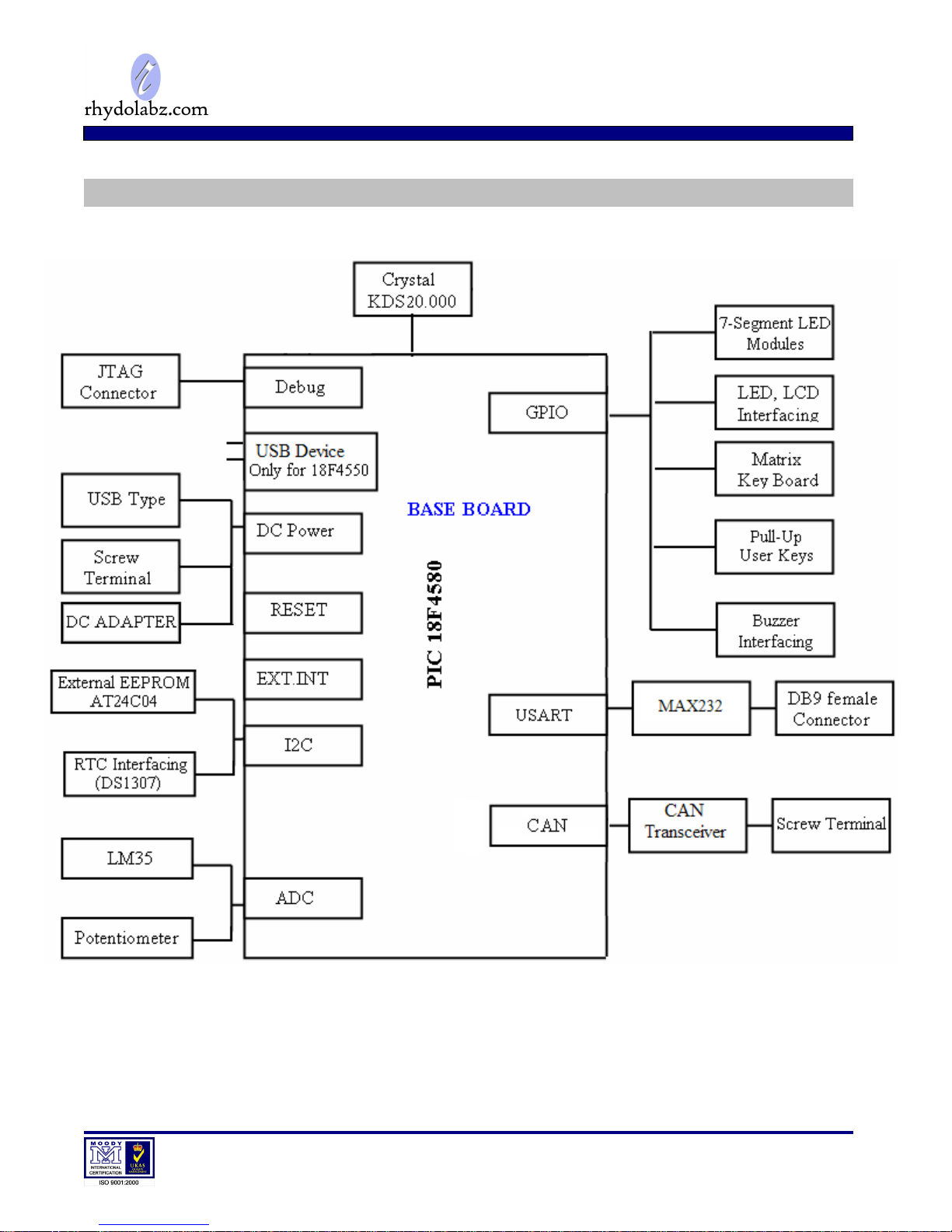
The eCee-PIC18F4580 Development and Evaluation Board from RhydoLabz can be used to
evaluate and demonstrate the capabilities of microchip PIC18F4580 microcontrollers. The board is
designed for general purpose applications and includes a variety of hardware to exercise
microcontroller peripherals. Ideally suitable for training and development purposes.
Compact and Ready to use design
Professional and Fully EMI/RFI Complaint PCB Layout Design for Noise Reduction
High Quality Two layer PTH PCB
Includes PIC18F4580 Microcontroller with built-in CAN Module
Board Supports PIC 16F877A/18F 4520/4550 Microcontrollers
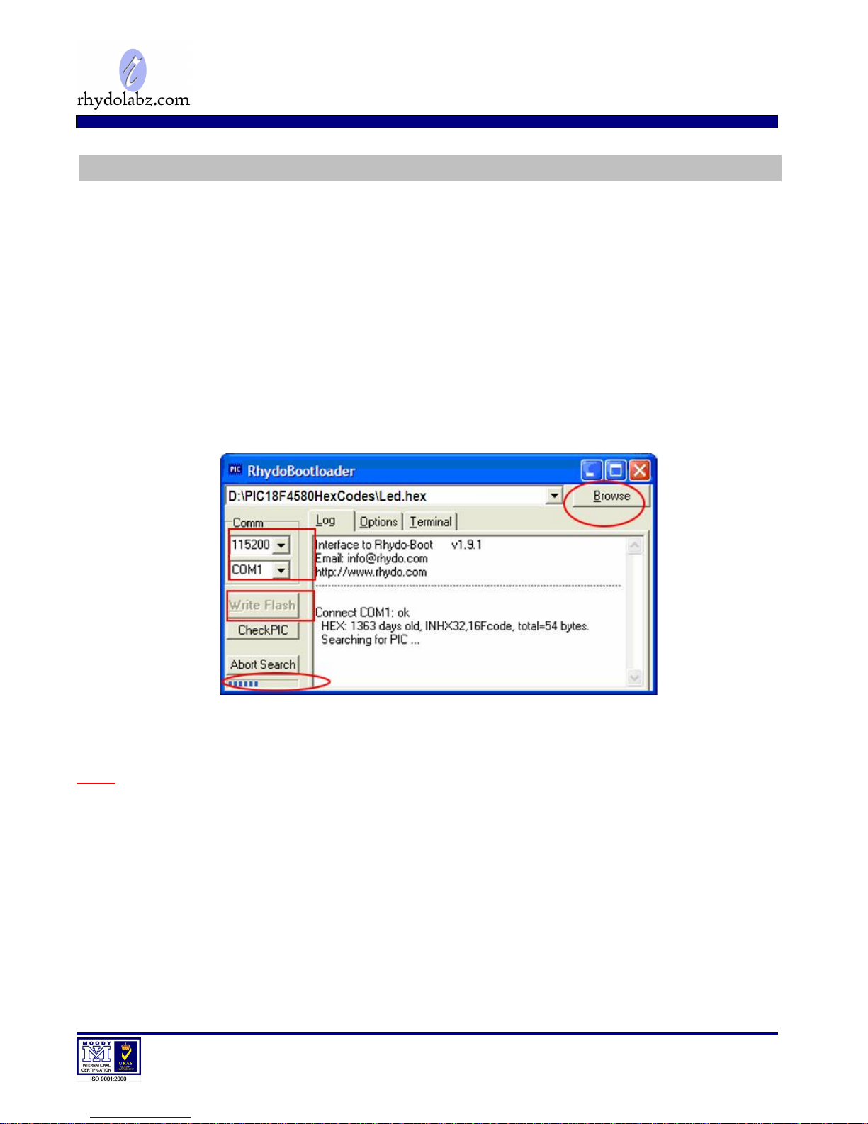
No separate programmer required (Built in Boot loader)
No Separate power adapter required (USB power source)
Screw terminal for External power Supply (with Jumper Select Option)
External Power Supply range of 7V to 20V
Adaptor (any standard 9-12V power supply) option
RS-232 Interface (For direct connection to PC’s serial port)
On board Two Line LCD Display (2x16)
On board I2C EEPROM (4K-AT24C04)
On board I2C RTC (DS 1307) with Crystal and Battery
On board 32.768 KHz Crystal for RTC
Four multiplexed 7-Segment LED Display
Built in Matrix keyboard (12 keys)
Built in Pull-Up (4 Keys) Keyboard
Built in IR Sensor Interface – TSOP 1738
Built in 8 LED Interface to test I/O
On Board External Interrupt and Reset buttons
Built in Potentiometer interface for ADC
On Board Temperature Sensor Interface

www.rhydolabz.com
We bring the world to you..
eCee PIC
18F4580
PACKAGE
CONTENTS
On Board Buzzer Interface
On Board PWM Output pin
Screw terminal for CAN BUS (with Jumper Select Option)
On Board CAN Transceiver IC
On Board ICD Connector for Debugging/Programming
On Board ICSP Connector
On Board 20 MHz Crystal Oscillator
On Board Power LED Indicator
On Board DB9 Connector
On Board USB Connector
All Port Pins available at IDC (2x5) Connector
Power Supply Reverse Polarity Protection
On Board 1 Amp Voltage Regulator
Can be used as main board for developing applications
Demo HEX codes included for testing of board features
Example codes included
Fully Assembled and Tested eCee PIC18F4580 Development board
Software CDROM with
oSchematic
oProgramming Software
oSample Hex Code
oExample Codes for
Led Blinking LCD Display
Matrix Keyboard External Interrupt Interfacing
I2C Protocol 7-Segment Display
Led Control with Timer0 UART Communication
PWM Generation Buzzer Interfacing
ADC Interfacing Pull-Up Keyboard
Capture Module Compare Module
Timer 1 Timer 2
CAN Communication

www.rhydolabz.com
We bring the world to you..
PIC1
8F45
8
0
SPECIFICATION
S
High Performance RISC CPU
32 KB Programmable Flash Memory
1536 bytes Data Memory (SRAM)
256 bytes EEPROM
Supports Up to 40 MHz Operation
36 I/O pins
11-Channel 10-bit Analog to Digital Converter(ADC)
One Capture module/ Compare Module/PWM Module
One Enhanced Capture Module/ Compare Module/ PWM module
One ECAN Module with Message bit rates up to 1 Mbps
Parallel Communications (PSP) Support
One 8-Bit Timer/Counter and Three 16-Bit Timer/Counter
One Enhanced USART (Supports RS-232, RS-485 and LIN 1.3)
One Master Synchronous Serial Port (MSSP)
One Serial Peripheral Interface(SPI) Module
One Inter-Integrated Circuit (I2C) Module
Power-On Reset (POR), Power-Up Timer (PWRT) and Oscillator Start-up Timer (OST)
Interrupt Capability (up to 20 sources)
Three External Interrupts
In-Circuit Serial Programming (ICSP) via two pins
In-Circuit Debug (ICD) via two pins
Self Programmable under software control
Programmable Brown Out Reset
Low Voltage Programming
Power Saving Sleep Mode
Extended WatchDog Timer(WDT)
Wide Operating Voltage 2.0V to 5.5V
Low Power Consumption using nanoWatt Technology

www.rhydolabz.com
We bring the world to you..
FUNCTIONAL BLOCK

www.rhydolabz.com
We bring the world to you..
INTERFACE OVERVIEW
LCD Module
PIC
18F45
8
0
IC
BUZZER
MAX232N
RESET SWITCH
PULL UP
KEYBOARD
IR SENSOR
EXTERNAL POWER
(7V
-
20V)
VOLTAGE REGULATOR
3×4 MATRIX KE
YBOARD
USB POWER
INTERFACE
DB9 CONNECTOR
(SERIAL INTERFACE)
EXTERNAL EEPROM
EXTERNAL INTERRUPT KEY
LCD CONTRAST KNOB
RJ
-
45 CONNECTOR
LED ARRAY
RTC BATTERY UNDER
THE LCD SCREEN
ADC KNOB
TEMPER
ATURE
SENSOR
-
LM35
CAN PORT
(CANH and CANL)
7
-
SEGMENT DISPLAY
ADAPTER PLUGIN
PORTB PINOUTS
PORTC PINOUTS
PORTD PINOUTS
CAN
TRANSCEIVER IC
PORTA and PORTE PINOUTS

www.rhydolabz.com
We bring the world to you..
POWER SUPPLY
CLOCK SOURCE
eCee PIC18F4580 Board has three power supplies; you can choose one of the following ways to
supply power :
(1) Through a Screw Terminal (7V - 20V External DC Power Supply)
(2) Through the motherboard USB port
(3) Through an adapter (7V - 20V External DC Power Supply)
The Power Supply circuit is given below:
eCee PIC18f4580 evaluation board has two clock sources:
32.768 KHz as the RTC clock source
20 MHz Crystal as the MCU clock source
Vin
1
GN D
2
Vout 3
U3
LM7805
D- 1
VCC 2
D+ 3
GND 4
K1
USB
1
2
3
K2
POWERSELECTION
+5
D9
1N4007
1
2
K3
CONN2PIN
C9
470MF/40V C5
0.1MF C6
0.1MF
C10
47MF/16V
R43
470R
D10
PWRLED
J1
DCPOWER
+12V
DC
USB
DC

www.rhydolabz.com
We bring the world to you..
SETTING UP eCee PIC
18f45
8
0
Power the development board with a USB Cable.
Make sure that the Power-On LED is ON and the jumper is in proper position.
Connect the RS-232 Cable to the COM port of your computer.
Connect the other end to the Serial Port of your Demo Kit.

www.rhydolabz.com
We bring the world to you..
PROGRAMMING STEPS
The PIC18F4580 Demo Kit is preloaded with Boot loader firmware. This allows the user to program
the microcontroller without using separate programmer.
1. Setup Rhydo Boot Loader.
2. Select COM port and set Baud rate as 115200 bps.
3. Browse your Hex files.
4. Ensure RS-232 connection and power connection.
5. Click the Write Flash button.
6. Reset PIC using the Reset button while Boot loader searches for PIC.
Note: The microcontroller is preloaded with boot-loader software. Programming with other
devices/programmers or removing the microcontroller from the development board could damage the
boot-loader. In this case, the company won’t be liable for the damages caused and no
replacement/refunding/reloading is entertained.

www.rhydolabz.com
We bring the world to you..
TECHNICAL SUPPORT
If you are experiencing a problem that is not described in this manual, please contact us. Our
phone lines are open from 9:00 AM – 5.00 PM (Indian Standard Time) Monday through Saturday
LIMITATIONS AND WARRANTEES
This product is intended for personal or lab experimental purpose and in no case should be used where
it harmfully effect human and nature. No liability will be accepted by the publisher for any
consequence of its use. Use of the product software and or hardware is with the understanding that any
outcome whatsoever is at the users own risk. All products are tested for their best performance before
shipping, still rhydoLABZ is offering One year Free service warranty (Components cost + Shipping
cost will be charged from Customer).
DISCLAIMER
Copyright © Rhydo Technologies (P) Ltd
All rights are reserved. Reproduction in whole or in part is prohibited without the prior written consent
of the copyright owner. The information presented in this document does not form part of any
quotation or contract, is believed to be accurate and reliable and may be changed without notice.
Rhydo Technologies (P) Ltd.
(An ISO 9001:2008 Certified R&D Company)
Golden Plaza, Chitoor Road,
Cochin – 682018, Kerala State, India
Phone : 0091- 484-2370444, 2371666
Cell : 0091- 99466 70444
Fax : 0091 - 484-2370579
E-mail : info@rhydolabz.com, sales@rhydolabz.com
WebSite : http://www.rhydolabz.com
Table of contents
Other Rhydolabz Motherboard manuals