Ricmotech GTpro1 User manual

GTpro1 Gen2 Pedals Setup Guide

Features and Benefits
•Built using real after-market automotive pedals
•Brake can read up to 100lbs of pedal force, can be higher upon request
•Brake has exponentially increasing resistance like real brakes
•Brake pedal firmness is infinitely adjustable
•Brake designed to push back with hydraulic fluid rather than a spring
•Real master cylinder on brake and clutch with metal reservoir to eliminate breakage and leaks
•Industrial pressure sensor on master cylinders reads pedal forces with high accuracy
•Pedal adjustability as possible in a real car
•Remote sensor unit for brake has user-changeable resistance modules to tailor the pedal resistance
•Brake pedal has small initial dead zone typical of the master cylinder bypass valve closing
•Optional resistance modules provide different brake pedal resistance effects
•Microcontroller based Intelligent Pedal Control Unit (PCU)
•PCU firmware is upgradable
•Reads pedals 1000 times per second
•Up to 1,000 pedal updates sent to game per second (PC Limitation)
•Electronic adjustable dead zones and limits for all pedals
•Changeable response (linearity) curves for all pedals imitates characteristics of various brake pad compounds, clutch
materials, and carburetor/throttle body responses
•Stores Profiles in on PC
•Baseline Settings Stored In Black Box EEPROM to work across all games
•Powered by USB
•For PC only
•Compatible with Win XP, Vista, 7, 8 and 10 (32- and 64-bit)
•Simple Installation
•Free Technical Support
•One-year warranty on mechanical components
•Two-year warranty on electronic components

Congratulations on your purchase of the most realistic sim-racing pedals available. This setup guide will help you get the most out of
your new GTpro pedals. Your GTpro pedals will provide you with all the adjustability that they would have in a real race car in order
to provide you with the purest sim-racing experience possible.
Your pedals arrive to you fully filled and purged. The PCU (pedal control box) is calibrated for your pedals before shipping and are
ready to drive after they have been mounted.
About this Manual
As we continue to improve the design of the pedals, some photos may not reflect all the upgrades and therefore may differ from the
product you receive.
Tools and Items Required for Installation (not included)
•Mounting bolts, nuts, and washers
•Drill and drill bits
•Screwdrivers and wrenches
Step 1: Getting Your Pedals Ready for Installation
The brake pedal has been secured in the down position to prevent air from getting trapped at the pressure sensor during shipping.
This is done to avoid the need to bleed the brake at the time of installation. Do not remove the strap yet. Check that the reservoir is
filled to about 30% capacity with fluid.
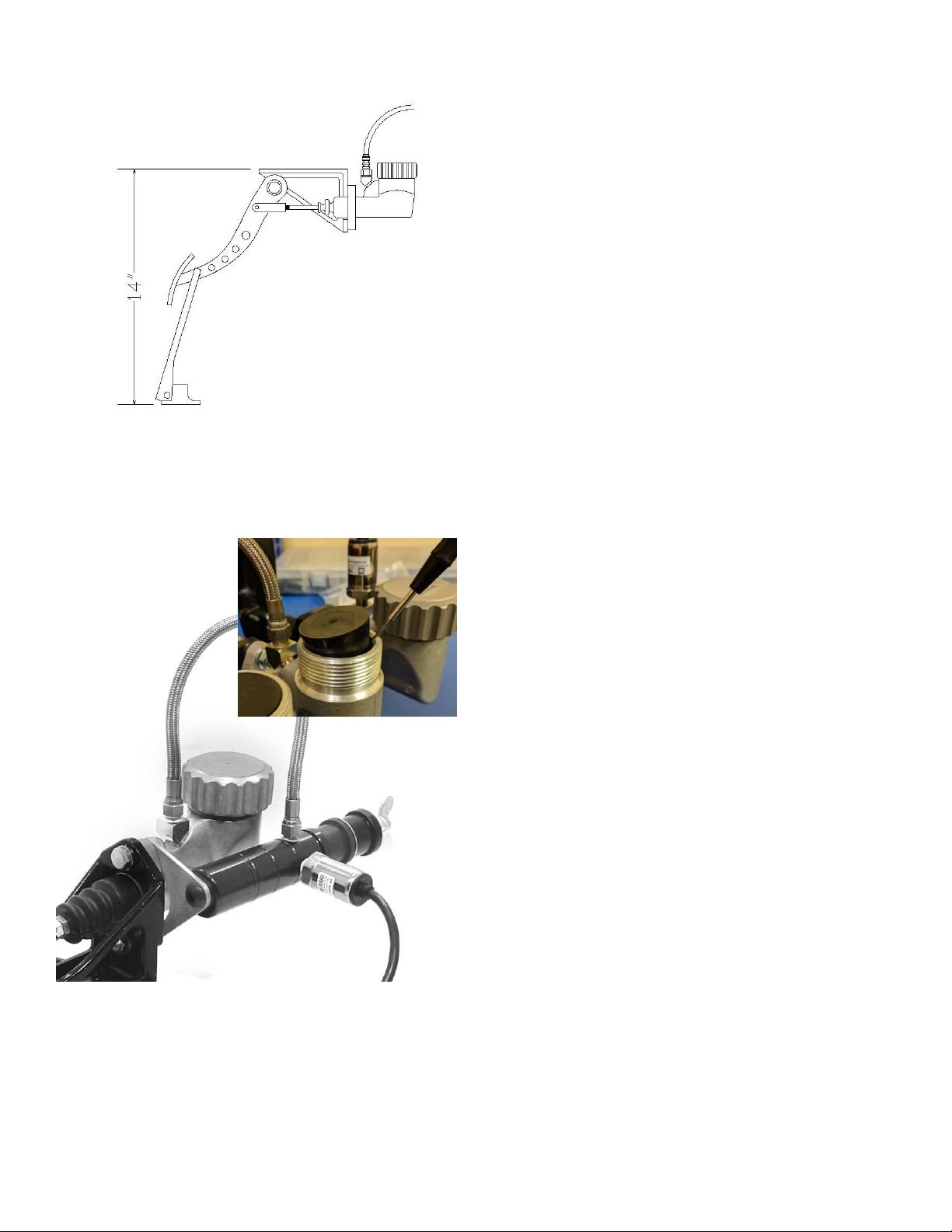
Set the pedal assembly tilted to 45 degrees, as shown, for a period of 5 minutes to allow any air bubbles to rise to the top of the
reservoir. Remove the strap holding down the pedal and press on the pedal with your hand, the pedal should not move more than ¼
inch (6mm) before the stacking units begin to squeeze. Turn assembly upright and do not lay it on its side from this point forward.
Purging Procedure
If the pedal does move more than ¼ inch (6mm) without squeezing on the stacking units then air has made its way into the system
during shipping. To remove the air, begin by removing the nuts that keep the stacking units in place (refer to figure 3 on next page)
and putting the wing nut back on. Keep the pedal assembly tilted as indicated above and hold the remote sensor assembly below
the height of the pedal. While holding the sensor assembly with the hose exiting straight up, pump the stacking unit shaft in and out
with your hand about 5 to 10 times to flush any air bubbles to the reservoir above. Reinstall the stacking units and test the pedal, if
the problem persists then repeat the steps above.
The pedal should also be pumped before any racing to prime the system and build up pressure in the system.
ATTENTION! The clutch reservoir ships empty and should remain empty at all times. This is intentional. Adding fluid will overload
the sensor and will result in permanent failure.
Step 2: Mounting Your Pedals
Identify each pedal by the markings on the reservoir cap.

Ricmotech recommends hard mounting the pedals directly to your sim-racing chassis. The mounting positions suggested are only
that, a suggestion. Please feel free to change the placement of the pedals to accommodate your preferred driving style.
Suspended pedals should be mounted at a height of about 17 inches (43cm) above the sim-chassis floor. The pedals should be
mounted so the brake pedal is approximately even with the throttle pedal when it is fully depressed, typically about 1 inch (25mm),
but this may vary based upon the pedal firmness setting. Mount the pedals using ¼ inch or 6mm thick bolts or screws (not included).
Use nuts and washers to be sure the screws will not pull out.
Your pedals may include a mounting frame to facilitate the placement of your pedals.
Position the remote sensor assembly as shown in the image below. Be sure the hose is
not stretched or kinked.
Route the cables to avoid having them get pinched or chafed using zip ties. Mount the PCU (Pedal Control Unit) in a location that is
both out of the way yet within reach of the driver, such as next to your wheel.
Open the brake fluid reservoir and pry out the rubber plug. This plug is only to prevent spills during transport. Keep the plug in case
the pedals or rig need to be moved in the future.

The initial position of the brake and clutch pedal can be adjusted by threading the master cylinder rod into or out of the clevis. First
loosen the jam nut and then rotate the master cylinder shaft. After you have reached the desired position tighten the jam nut to
prevent it from moving.
Step 3: Making the Connections
Plug the pedals into the PCU as follows:
Port A = Throttle
Port B = Brake
Port C = Clutch
Port D = Hand Brake (Optional)
Port E = (Spare for warranty purposes)
Windows will install its internal drivers. The pedals are powered from the USB port, no external power is required.
Step 4: Test Your Pedals to be Sure Windows has Installed Drivers Correctly
Windows XP, Vista, and 7: click Start, type: joy.cpl and ENTER
Windows 8: go to the Start screen, type: joy.cpl and ENTER
Windows 10: hit the “Windows”key, type: joy.cpl and ENTER
The Game Controllers panel will open and there should be a controller named GTpro Gen2, double click on it. A window with several
axis and buttons should appear. Press each pedal in sequence and verify the X, Y and Z axis respond. If they do then Windows has
properly installed the drivers and the data is getting to the PC. There are other axis and buttons displayed in this window. Those are
not used at this time but are there for future use.
If your Game Controllers panel opens but does not show any axis or buttons, please go to the next step. There is an unresolved bug
that may cause Windows to install an incorrect driver for the pedals. Your pedals will still function in the game. If you wish to resolve
the issue and are comfortable navigating through the windows registry, then please contact Ricmotech support and someone will
walk you through the steps to resolve this.
Open your favorite racing sim title and navigate to the controllers setup screen. Set the new axis for each pedal according to that
software’s procedure. It is recommended to calibrate each pedal to its maximum and remove any linearity or other custom settings
in the sim. The pedal PCU will allow customizations to be done and will be retained in the pedal PCU memory. The settings in the
pedal PCU will work in every game. Setting custom settings in both the pedals and the game can yield undesired results.
Step 5: Programming and Calibration
Follow the instructions in the SmartPanel User Guide to make electronic adjustments to the pedals.

Optional Brake Tuning Kit
An optional brake tuning kit is available for those that want to
tailor the sensation of the brake pedal. The kit includes two
soft bushings (orange), two medium bushings (black), and
one hard spacer. When these are used in conjunction with
the original bushings (hard red bushing and extra-hard black
bushing) there are 10 combinations possible.
When placing the bushings on the slave cylinder, it does not
matter in which position they are placed, the resulting
firmness is the same. Use the table below to achieve the
desired firmness, where 1 is the softest combination and 10 is
the firmest combination.
Bushing Combinations
Bushing 1
Bushing 2
Firmness Rating
Stepped Black
Hard Spacer
10
Stepped Red
Hard Spacer
9
Cylindrical Black
Hard Spacer
8
Cylindrical Orange
Hard Spacer
7
Stepped Black
Stepped Red
6 (Stock)
Stepped Black
Cylindrical Black
5
Stepped Black
Cylindrical Orange
4
Cylindrical Black
Cylindrical Black
3
Cylindrical Black
Cylindrical Orange
2
Cylindrical Orange
Cylindrical Orange
1
Table of contents
Other Ricmotech Music Pedal manuals