Ricmotech GTpro3 Gen2 Assembly instructions

GTpro3 Gen2 Pedals
Installation and Setup Guide

Features and Benefits
•Built using real Tilton 600 Series after-market automotive pedals
•Adjustable pedal stops for both ends of travel on throttle
•Magnetic Hall-Effect sensor on throttle pedal is contact-less for long life and high accuracy
•Brake can read up to 175lbs of pedal force
•Brake has exponentially increasing resistance like real brakes
•Brake pedal firmness is infinitely adjustable
•Brake designed to push back with hydraulic fluid rather than a spring
•Real master cylinder on brake and clutch with metal reservoir to eliminate breakage and leaks
•Industrial pressure sensor on master cylinders reads pedal forces with high accuracy
•Pedal adjustability as possible in a real car
•Remote sensor unit for brake has user-changeable resistance modules to tailor the pedal resistance
•Brake pedal has small initial dead zone typical of the master cylinder bypass valve closing
•Optional resistance modules provide different brake pedal resistance effects
•Microcontroller based Intelligent Pedal Control Unit (PCU)
•PCU firmware is upgradable
•Reads pedals 1000 times per second
•Up to 1,000 pedal updates sent to game per second (PC Limitation)
•Electronic adjustable dead zones and limits for all pedals
•Changeable response (linearity) curves for all pedals imitates characteristics of various brake pad compounds, clutch
materials, and carburetor/throttle body responses
•Stores Profiles in on PC
•Baseline Settings Stored In Black Box EEPROM to work across all games
•Powered by USB
•For PC only
•Compatible with Win XP, Vista, 7, 8 and 10 (32- and 64-bit)
•Simple Installation
•Free Technical Support

Congratulations on your purchase of the most realistic sim-
racing pedals available. This setup guide will help you get the
most out of your new GTpro3 Xtreme pedals. Your GTpro3
pedals will provide you with all the adjustability that they
would have in a real race car to provide you with the purest
sim-racing experience possible.
About this Manual
As we continue to improve the design of the pedals, some
photos may not reflect all the upgrades and therefore may
differ from the product you receive.
Tools and Items Required for Installation (not included)
•Mounting bolts, nuts, and washers
•Drill and drill bits
•Screwdrivers and wrenches
Step 1: Getting Your Pedals Ready for Installation
Mount the slave cylinder to the mounting bracket as shown.
The brake pedal has been secured in the down position to
prevent air from getting trapped at the pressure sensor
during shipping. This is done to avoid the need to bleed the
brake at the time of installation. Do not remove the strap yet.
Remove the “leak-prevention” stoppers from the reservoir
and store them for transporting your pedals in the future.
Check that it is filled to about 30% capacity with fluid.
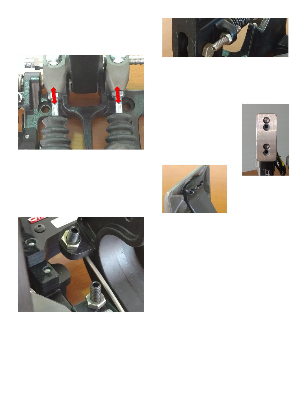
Set the pedal assembly tilted to 45 degrees, as shown, for a
period of 5 minutes to allow any air bubbles to rise to the top
of the reservoir. Remove the strap holding down the pedal
and press on the pedal with your hand, the pedal should not
move more than ¼ inch (6mm) before the stacking units
begin to squeeze. Turn assembly upright and do not lay it
sideways from this point forward.
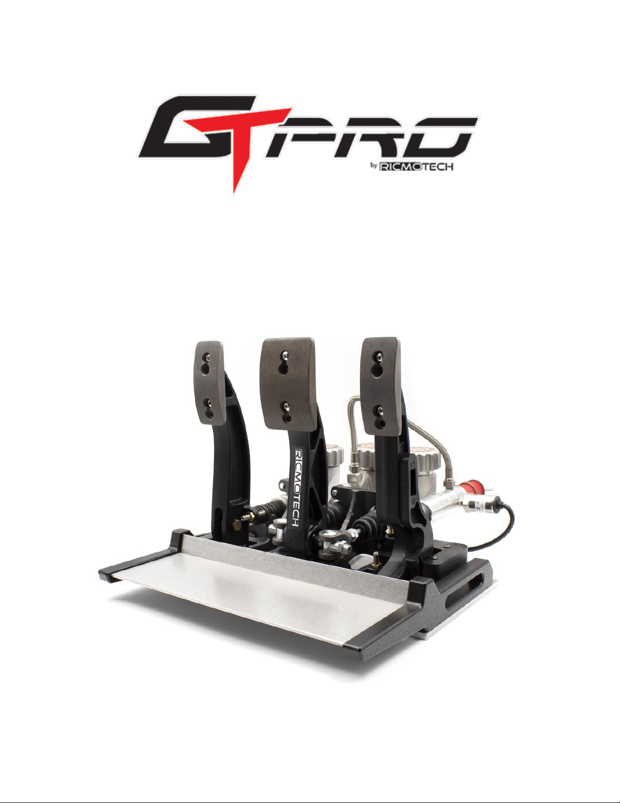
If the pedal does move more than ¼ inch (6mm) without
squeezing on the stacking units then air has made its way into
the system during shipping. To remove the air, begin by
removing the nuts that keep the stacking units in place (refer
to figure 3 on next page) and putting the wing nut back on.
Keep the pedal assembly tilted as indicated above and hold
the remote sensor assembly below the height of the pedal.
While holding the sensor assembly with the hose exiting
straight up, pump the stacking unit shaft in and out with your
hand about 5 to 10 times to flush any air bubbles to the
reservoir above. Reinstall the stacking units and test the
pedal, if the problem persists then repeat the steps above.
The pedal should also be pumped before any racing to prime
the system and build up pressure in the system.
ATTENTION! The clutch reservoir ships empty and should
remain empty at all times. This is intentional. Adding fluid
will overload the sensor and will result in permanent failure.
Step 2: Mounting Your Pedals
Ricmotech recommends hard mounting the pedals directly to
your sim-racing chassis. The mounting positions suggested
are only that, a suggestion. Please feel free to change the
placement of the pedals to accommodate your preferred
driving style.
Pre-drill mounting holes in the floor of your racing simulator
according to the template provided. Secure the pedals using
5/16 inch or 8mm thick bolts or screws (not included). Use
nuts and washers to be sure the screws will not pull out.
Route the cables to avoid having them get pinched or chafed
using the supplied cable straps. Mount the PCU in a location
that is both out of the way and within reach of the
programming switch.

The initial position of the brake pedal can be adjusted by
threading the master cylinder rod into or out of the clevises.
First loosen the jam nut and then rotate the master cylinder
shaft. After you have reached the desired position tighten the
jam nut to prevent it from moving.
The starting and ending positions of the throttle pedal can be
adjusted by turning the stop screws located to the left of the
throttle pedal. Turning clockwise will reduce the travel and
counter-clockwise will increase the travel. Tighten the lock
nuts when complete to prevent the settings from changing.
Over-extending the pedal range is not recommended as it
places additional strain on the spring which may cause them
to break. The spring is a consumable item and replacements
can be purchased as needed.
Similarly, the clutch pedal ending position can be adjusted by
turning the stop screw located to the right of the pedal.
Turning the screw clockwise will reduce the travel, while
turning the screw counter-clockwise will increase the travel.
Tighten the jam nut when the adjustments are complete to
prevent the setting from changing.
When any adjustments are made to the travel of the throttle
or clutch pedal, those pedals should be recalibrated by
setting the new Absolute Min and Absolute Max in the
SmartPanel software.
The pedal faces can be installed in one of 4 different positions
vertically and 3 different positions
horizontally. The height can be
adjusted to two different positions
by moving the pedal face to the
other screw hole and can be set to 2
additional positions by flipping the
pedal face upside-down. The holes
are drilled off-center to allow four
different positions.
Three different horizontal
positions can be attained by
moving the pedal to one of
the other three mounting
holes on the pedal arm.
Step 3: Making the Connections
Plug the pedals into the PCU as follows:
Port A = Throttle
Port B = Brake
Port C = Clutch
Port D = Hand Brake (Optional)
Port E = (Spare for warranty purposes)
Windows will install its internal drivers. The pedals are
powered from the USB port, no external power is required.
Step 4: Test Your Pedals to be Sure Windows has Installed
Drivers Correctly
Windows XP, Vista, 7 and 10: click Start, type: joy.cpl and
ENTER
On Windows 8 and 8.1 go to the Start screen, type: joy.cpl
and ENTER
The Game Controllers panel will open and there should be a
controller named GTpro Gen2, double click on it. A window
with several axis and buttons should appear. Press each pedal
in sequence and verify the X, Y and Z axis respond. If they do
then Windows has properly installed the drivers and the data

is getting to the PC. There are other axis and buttons
displayed in this window. Those are not used at this time but
are there for future use.
If your Game Controllers panel opens but does not show any
axis or buttons, please go to the next step. There is an
unresolved Windows issue that may cause this. Your pedals
will still function in the game. If you wish to resolve the issue
and are comfortable navigating through the windows registry,
then please contact Ricmotech support and someone will
walk you through the steps to resolve this.
Open your favorite racing sim title and navigate to the
controllers setup screen. Set the new axis for each pedal
according to that software’s procedure. It is recommended to
calibrate each pedal to its maximum and remove any linearity
or other custom settings in the sim. The pedal PCU will allow
customizations to be done and will be retained in the pedal
PCU memory. The settings in the pedal PCU will work in every
game. Setting custom settings in both the pedals and the
game can yield undesired results.
___________________________________________________________________________________________________________
Adjusting the Brake Pedal Firmness
The firmness can be adjusted by turning the “bias”screw.
Loosening the bias locknut and turning the screw clockwise
will make the pedal firmer, while turning the screw counter-
clockwise will make the pedal softer. It is possible to add a
remote bias adjuster to perform this operation while sitting in
the driver’s seat. Tighten the locknut when adjustments are
complete to prevent the adjustment from changing.
It is recommended to first adjust the pedal firmness to your
liking first, then calibrating the point of maximum braking
electronically (100% braking).
An optional brake tuning kit is available for those that want to
tailor the sensation of the brake pedal. The kit includes two
soft bushings (orange), two medium bushings (black), and
one hard spacer. When these are used in conjunction with
the original bushings (hard red bushing and extra-hard black
bushing) there are 10 combinations possible.
The pedals are set up so that the master cylinder on right is at
its firmest, while the master cylinder on the left is set softer
and can be adjusted by changing bushings. The “bias”
adjustment allows the user to make the pedal favor the soft
side or the firm side. This is how infinite adjustability is
achieved.
Care should be taken when softening the brake pedal to be
sure mechanism does not bind causing strain to the pedal and
master cylinder assembly. In the fully pressed position be
certain the knuckles do not bind against both sides of the
pedal arm. The mechanism can slide side-to-side so at least
one side needs to have clearance.
When placing the bushings on the slave cylinder, it does not
matter in which position they are placed, the resulting
firmness is the same. Use the table below to achieve the
desired firmness, where 1 is the softest combination and 10 is
the firmest combination.
Bushing Combinations
Bushing 1
Bushing 2
Firmness Rating
Stepped Black
Hard Spacer
10
Stepped Red
Hard Spacer
9
Cylindrical Black
Hard Spacer
8
Cylindrical Orange
Hard Spacer
7
Stepped Black
Stepped Red
6 (Stock)
Stepped Black
Cylindrical Black
5

Stepped Black
Cylindrical Orange
4
Cylindrical Black
Cylindrical Black
3
Cylindrical Black
Cylindrical Orange
2
Cylindrical Orange
Cylindrical Orange
1
This pedal set has the ability to replicate the pedal firmness of
various styles of race cars. There are many factors that affect
the way a pedal should feel based on the type of car being
simulated. In a white paper titled “Brake Systems and
Upgrade Selection”published by Stephen Ruiz, Engineering
Manager and Carroll Smith, Consulting Engineer at StopTech
LLC, all aspects of a high performance racing brake system are
discussed. The full document is available at:
http://www.stoptech.com/technical-support/technical-
white-papers/brake-system-and-upgrade-selection
For our purposes, we are only interested in the section about
brake firmness and modulation. Here is an excerpt as it
applies to racing simulators:
BRAKE PEDAL FIRMNESS AND MODULATION
The human brain/body system modulates most effectively by force,
not by displacement. The side control sticks on current fighter aircraft
hardly move. The feel of the brake pedal should approach the firmness
and consistency of a brick. There are several factors at work here:
1) Brake hoses: Optimum pedal firmness cannot be achieved with the
stock fabric reinforced rubber flexible hoses which swell under
pressure - decreasing pedal firmness while increasing both pedal travel
and brake system reaction time. The first step in upgrading the
braking system of any vehicle is to replace the OEM flexible hoses
with. . .
2) Master cylinders and Caliper piston diameters: While it is true that
the most effective master cylinder arrangement is the twin cylinder
with adjustable bias bar that is universal in racing, replacing the OEM
master cylinder on a road going car is simply not practical. When
selecting an aftermarket system, make sure that the caliper bores are
designed for the specific application.
3) Disc run out and thickness variation: Run out in excess of six
thousandths of an inch (0.006") can be felt by the driver as can more
than 0.001" of thickness variation and any amount of material transfer
from overheated pads. Run out is caused by poor design of either
vanes or the junction between the friction surfaces and the mounting
bell, by poor machining, by thermal stress or by any combination of
the three.
4) Caliper and caliper mounting stiffness: Clamping force tries to open
the opposing sides of the calipers - resulting in a longer than optimum
pedal travel and uneven pad wear. The only solution is optimal
mechanical design and material selection - there is no effective
development fix for "soft" calipers. . .
Other Ricmotech Music Pedal manuals