RIDGE RYDER RR50A User manual

RIDGE
ACCESSORIES
PAGE 1
PRO HANDHELD
52
PLU 564552

PAGE 2
INTRODUCTION
WELCOME
Thank you for purchasing the Ridge Ryder RR50A 5 Watt UHF CB Radio. Please ensure that you
have read the product manual and instructions in full, prior to installation and use.
Failure to do so may result in product failure/damage or incorrect operation and therefore impact
the product performance.
FEATURES
The Ridge Ryder RR50A 5 Watt UHF CB Radio kit includes a rechargeable 5 Watt handheld radio,
240V charging dock, and 12V in car charger, belt clip and hand strap. Key radio features include:
• Up to 15km range • VOX voice operated exchange
• 5 Watt transmission power • LED torch light
• 80 Narrowband channels • FM radio
• Squelch control (automatic) • 10 call ring tones
• CTCSS (38ch)/ DCS (83ch) codes • Roger beep
• Duplex range extender • Button beep
• Channel scan function • Changeable backlight display (Blue, orange and purple)
• Dual channel monitor
BOX CONTENTS
.
Instruction
Manual
Antenna Li-ion Battery Charger
AC Adaptor
Belt Clip
(including screws)
Car Charger
Earphone Hand Strap

PAGE 3
CONTENTS
SAFETY INFORMATION AND WARNINGS........................................ PAGE: 4
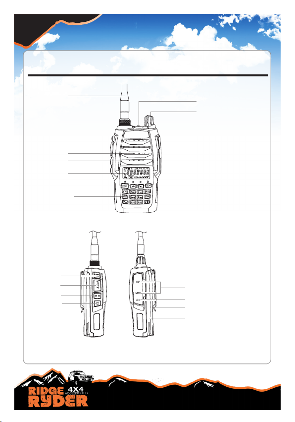
RADIO CONTROLS
...............................................................................PAGE: 6
LCD DISPLAY & BATTERY INFORMATION....................................... PAGE: 7
INSTALLING BATTERY & BELT CLIP
..................................................
PAGE: 7
CHARGING & BATTERY MAINTENANCE
............................................
PAGE: 8
RADIO OPERATION
- Power ON/OFF
.................................................
PAGE: 9
- Volume control
..................................................
PAGE: 9
- Battery voltage display
......................................
PAGE: 9
- FM Radio scan function ................................... PAGE: 9
- LED light
...........................................................
PAGE: 9
-
Keypad lock
......................................................
PAGE: 9
CHANNEL OPERATIONS
- Setup
...............................................................................
PAGE:10
- CTCSS & DCS decode setup
..........................................
PAGE:10
- CTCSS & DCS encode setup
..........................................
PAGE:10
- CTCSS & DCS encode/decode sync setup .....................PAGE:11
- Offset function
...................................................................
PAGE:11
- Wide/Narrow band setup
...................................................
PAGE:11
- Frequency reverse/talk around setup
................................
PAGE:12
- Busy channel lockout
.........................................................
PAGE:12
- PTT ID setup
......................................................................
PAGE:12
- TX off
..................................................................................
PAGE:13
BACKGROUND OPERATIONS
- TOT timer setup
...............................................................
PAGE:13
- VOX/ VOX delay / VOX beep setup
.................................
PAGE:14
- Frequency step size setup
...............................................
PAGE:15
- Squelch level /
Battery save
setup
...................................
PAGE:15
- LCD backlight/ colour setup
...............................................
PAGE:16
- Scan dwell time setup
........................................................
PAGE:16
- Display mode/ Primary channel setup
...............................
PAGE:17
- Battery voltage setup
.........................................................
PAGE:17
- Factory reset
......................................................................
PAGE:18
- Channel selection
...............................................................
PAGE:18
- Scanning
............................................................................
PAGE:18
- Transmitting
........................................................................
PAGE:18
- Receiving
............................................................................
PAGE:18
FUNCTION
- CTCSS & DCS
.................................................................
PAGE:19
- Dual channel monitor (DCM)
...........................................
PAGE:19
- Button beep
......................................................................
PAGE:19
- Transmitting & receive procedure/range
..........................
PAGE:20
- Duplex mode
....................................................................
PAGE:21
DUPLEX INFORMATION
.......................................................................
PAGE:22
UHF CB CHANNEL GUIDELINES
.........................................................
PAGE:23
UHF CB CHANNELS AND FREQUENCIES
- UHF channel frequency table
..........................................
PAGE:24
- CTCSS tone table
............................................................
PAGE:25
- DCS code table
................................................................
PAGE:26
TECHNICAL SPECIFICATIONS
.............................................................
PAGE:28
TROUBLE SHOOTING GUIDE
...............................................................
PAGE:29
WARRANTY INFORMATION
..................................................................
PAGE:30

PAGE 4
SAFETY INFORMATION AND WARNINGS
INFORMATION ON SAFE OPERATION
Please read this information before installing or using your UHF radio.
The operation of your UHF radio in Australia is subject to conditions in the following Licence:
In Australia the ACMA Radio communications (Citizen Band Radio Stations) and in New Zealand by
MED the General User Radio Licence for Citizen Band Radio.
SAFETY AND GENERAL USE WHILST IN A VEHICLE
Check the State and Federal laws and regulations regarding the use of two way radios in the area
where you drive, and always obey them.
FOR VEHICLES FITTED WITH AIRBAGS
When using the radio in a vehicle, do not place your radio in the area over an airbag, or in the
airbag deployment area. Airbags inate with great force, if a radio is placed in the airbag
deployment area and the air bag inates, it may be propelled with great force and cause serious
injury to the occupants of the vehicle.
POTENTIALLY EXPLOSIVE ATMOSPHERES
Turn your radio OFF when in any area with a potentially explosive atmosphere. Sparks in such areas
could cause an explosion or re resulting in injury or even death. NOTE: Areas with potentially
explosive atmospheres are often, but not always clearly marked. They include fueling areas such
as below deck on boats; fuel or chemical transfer or storage facilities; areas where the air contains
chemicals or particles, such as grain, dust, or metal powders; and any other area where you would
normally be advised to turn of your vehicle engine.
BLASTING CAPS AND AREAS
To avoid possible interference with blasting operations; turn your radio OFF near electrical blasting
caps, or in a “blasting area”, or in areas posted: “Turn off the two way radio.” Obey all signs and
instructions.
EXPOSURE TO RADIO FREQUENCY ENERGY
Your two-way radio complies with Australian Communications Authority Radio Communications
(Electromagnetic Radiation-Human Exposure) Standard, 2003. To assure optimal radio performance
and make sure human exposure to radio frequency electromagnetic energy is within the guidelines
set out in the above standards always adhere to the following radio operating procedures.
RADIO OPERATION AND EME EXPOSURE
Unauthorised antennas, modications, or attachments could damage the radio and violate
compliance. DO NOT hold the antenna when the radio is “IN USE.” Holding the antenna reduces
the effective range. DO NOT use the radio if the antenna is damaged. If a damaged antenna makes
contact with a persons skin, a minor burn may result.

PAGE 5
SAFETY INFORMATION AND WARNINGS (continued)
ELECTROMAGNETIC INTERFERENCE/COMPATIBILITY
Nearly every electronic device is susceptible to electromagnetic interference (EMI). To avoid the pos-
sibility of electromagnetic interference and/or compatibility conicts, turn off the radio in any location
where posted notices instruct you to do so such as health care facilities.
AIRCRAFT
When instructed to do so, turn off your radio when on-board an aircraft. Any use of a radio must be in
accordance with applicable regulations per airline crew instructions.
MEDICAL DEVICES – PACEMAKERS
The Advanced Medical Technology Association recommends a minimum separation of 15cm be
maintained between a radio and pacemaker. These recommendations are consistent with the
independent research by, and recommendations of, the U.S. Food and Drug Administration. People
with pacemakers should:
•ALWAYS keep the radio more than 15cm away from the pacemaker when the radio is powered on.
•NOT carry the radio in the breast pocket (handheld models).
•Use the ear opposite the pacemaker to minimise the potential for interference.
•Turn the radio OFF immediately there is any reason to suspect that interference is taking place.
MEDICAL DEVICES – HEARING AIDS
Some radios may interfere with some hearing aids. In the event of such interference, you may want
to consult your hearing aid manufacturer to discuss alternatives.
MEDICAL DEVICES - OTHER
If you use any other personal medical device, consult the manufacturer of your device to determine
if it is adequately shielded from RF energy. You physician may be able to assist you in obtaining this
information.
GENERAL WARNINGS
Keep the radio out of reach of babies and/or young children. Never use your radio outdoors
during a thunderstorm.
BATTERIES
All batteries can cause property damage and/or bodily injury such as burns if conductive material
such as jewelery, keys, or beaded chains touch exposed terminals. The material may complete
an electrical circuit (short circuit) and become quite hot. Exercise care in handling any charged
battery, particularly when placing it inside a pocket, purse, or other container with metal objects.
Do not replace or charge batteries in a potentially explosive atmosphere. Contact sparking may
occur while installing or removing batteries and cause an explosion.

PAGE 6
RADIO CONTROLS
RADIO LAYOUT
.
LED light
Power / VolumeSwitch
Antenna
Speaker
Microphone
LCD
Numeric keys
Right PanelLeft Panel
PTT key
PF2
PF1
LED light
Speaker / Microphone jacks
Belt clip
DC charging jack
Battery

PAGE 7
Battery pack:
Match the battery pack with the corresponding guides on the back of the transceiver, and push it
upwards till it is fully locked by the battery latch. To remove the battery lift locking battery latch up
(see arrow direction). Note: If the battery needs to be stored, keep it in status of 50% discharged.
Belt clip:
Place the belt clip to the corresponding grooves on the back of the transceiver, and then screw it
clockwise with screws provided.
The battery pack is not charged at the factory; please charge it before use. Charging the battery pack
for the rst time after purchase or extended storage (more than 2 months) may not bring the battery
pack to its normal operating capacity. After fully charging/ discharging cycle for two or three times,
the operating capacity will reach its best performance. The battery pack life is over when its operating
time decreases even though it is fully and correctly charged. Change to a new battery pack.
Note: Batteries are only covered by a 1 year warranty.
Charger Applied
Please use the specic charger appointed by our company. Other models may cause explosion and
personal injury. After installing the battery pack, if the radio displays low battery with red ashing
lamp or voice prompt, please charge the battery.
▲ Always switch OFF the transceiver equipped with a battery pack before charging. Otherwise, it will
interfere with correct charging.
▲ To avoid interference with charging, please do not cut off the power or take out the battery during
charging.
▲ Do not recharge the battery pack if it is already fully charged. This may shorten the life of the
battery pack or damage the battery pack.
▲ Do not charge the battery or transceiver if it is damp. Dry it before charging to avoid danger.
LCD DISPLAY
INSTALLING THE BATTERY & BELT CLIP
Talk around
Negative offset frequency
Narrow band
Func
Signal
Frequency Reverse
VOX Function
CTCSS
Keypad Lockout
DCS
Battery indicator
Busy Channel
Channel serial number/
FUNC menu s/no
NOTE:
Battery capacity indicator(full) No power,replace battery pack or charge battery
Battery capacity remnant Real time display receiving signal
strength/Power Indicator
CHARGING & BATTERY MAINTENANCE

PAGE 8
You can charge the battery or transceiver separately.
1.Plug the AC adaptor into the AC outlet, and then plug the cable of the AC adaptor into the DC jack
located on the back of the charger. Charging indicator---Red.
2.Plug the battery or transceiver into the charger. Make sure that the battery is well connected with
charging connectors. Charging indicator---Red. Once fully charged. Charging indicator---Green.
It takes approximately 4 hours to fully charge the battery. But, the actual charging time depends on
the dump battery. After fully charged, please remember to remove the battery or transceiver out of
charger. Over charging will shorten the battery life and reduce its performance.
Connect the transceiver directly with adaptor or car charger to charge.
Note: Please power off the transceiver before charging the transceiver in this way. Also, it takes
longer time (totally 12hours) to fully charge the transceiver in this way.
How to Store the Battery
1.If the battery needs to be stored, keep it in status of 50% discharged.
2.It should be kept in low temperature and dry environment.
3.Keep it away from hot places and direct sunlight.
WARNING:
▲ Do not short circuit battery terminals.
▲ Never attempt to remove the casing from the battery pack.
▲ Never assemble the battery in dangerous surroundings, sparks may cause an explosion.
▲ Do not put the battery in hot environment or throw it into a re, it may cause an explosion.
CHARGING & BATTERY MAINTENANCE

PAGE 9
RADIO OPERATION
POWER ON/OFF
Turn “POWER/VOLUME” CONTROL KNOB clockwise to turn the RR50A ON. Turn “POWER/
VOLUME” CONTROL KNOB anticlockwise to turn the RR50A OFF
VOLUME CONTROL
Under power-on state, turn “POWER/VOLUME” CONTROL KNOB clockwise or anticlockwise to
adjust volume.
When unit is ON press “(FUNC) BUTTON”, a F icon will appear on the top left corner of
the screen then press “(1FM) BUTTON” and use the “UP ARROW” or “DOWN ARROW” to scan
for a radio station. To switch back to CB mode repeat above operation. If you have
problems with switching back to CB mode turn the RR50A OFF and ON and repeat
steps above.
Under standby state, press “(BLUE) BUTTON” on the side of the RR50A to switch on the LED light.
Press it again to switch off.
BATTERY VOLTAGE DISPLAY
FM RADIO SCAN FUNCTION
LED LIGHT
Under standby state, pressing [PF2], LCD displays current battery voltage. Press this button again to
clear the display.
KEYPAD LOCK
Press “(FUNC) BUTTON” and then press and hold the “(*ENT) BUTTON” for 2 seconds to lock the
keypad. A small key symbol will appear above the channel number to indicate the keypad is locked.
To unlock the keypad repeat the above. The small key symbol will now disappear from the display
and the keypad will be functional.
NOTE: When keypad is locked, only PTT / PF1 / PF2 / “(FUNC) BUTTON” are available.

PAGE 10
CTCSS/DCS DECODE SETUP
Channel operation refers to a temporary change on a current channel function. Once the
radio is turned off or switched to another channel, the temporary change will be erased. Under
frequency+channel mode, channel+Name Tag mode or VFO mode, the operating methods are as
follows:
1. After pressing the “(FUNC) BUTTON”, the top left corner of LCD displays an F icon, then press
“(8SET) BUTTON” to enter function menu.
2. Press “UP ARROW” or “DOWN ARROW” button to choose the desired function to be set.
3. Press “(FUNC) BUTTON” to enter into function menu setup.
4. Press “UP ARROW” or “DOWN ARROW” button to choose the desired contents to be set.
5. Press “(FUNC) BUTTON” to return to upward menu.
6. Press “(ESC/M) BUTTON”or “(*ENT) BUTTON” to conrm and exit.
NOTE: When transceiver works in professional transceiver mode, operation pressing “(FUNC)
BUTTON” followed by “(8SET) BUTTON” is not valid. Under frequency mode (VFO), once the radio
is turned off or changed to new VFO frequency, the channel operations setting will be remained until
next change.
CHANNEL OPERATIONS
If this function is enabled, you shield your radio from other transceivers of same frequency.
1. After pressing the “(FUNC) BUTTON”, the top left corner of LCD displays an F icon, then press
“(8SET) BUTTON” to enter function menu.
2. Press “UP ARROW” or “DOWN ARROW” button to choose No.1 function item. It shows “R-CDC”
on LCD
3. Press “(FUNC) BUTTON” to enter into function menu setup.
4. Press “(1FM) BUTTON” to choose CTCSS, DCS or OFF. When DCS signaling is selected, press
“(*T/R) BUTTON” to choose DCS positive and inverse code.
5. Press “UP ARROW” or “DOWN ARROW” button to choose the desired CTCSS / DCS encodes
signaling.
6. CTCSS: 67Hz- 254.1Hz, 50 groups in total, Default: 67Hz.
7. DCS: 017N-765I, 232 groups in total. “N” stands for positive code, “I” Stands for reverse code.
8. Press “(FUNC) BUTTON” to go back to previous menu. Press “(ESC/M) BUTTON”or “(*ENT)
BUTTON” to conrm and exit.
CTCSS/DCS ENCODE SETUP
1. After pressing the “(FUNC) BUTTON”, the top left corner of LCD displays an F icon, then press
“(8SET) BUTTON” to enter function menu.
2. Press “UP ARROW” or “DOWN ARROW” button to choose No.2 function item. It shows “T-CDC”
on LCD
3. Press “(FUNC) BUTTON” to enter into function menu setup.
4. Press “(1FM) BUTTON” to choose CTCSS, DCS or OFF. When DCS signaling is selected, press
“(*T/R) BUTTON” to choose DCS positive and inverse code.
5. Press “UP ARROW” or “DOWN ARROW” button to choose the desired CTCSS / DCS encodes
signaling.
6. CTCSS: 67Hz- 254.1Hz, 50 groups in total

PAGE 11
7. DCS: 017N-765I, 232 groups in total. “N” stands for positive code, “I” Stands for inverse code.
8. Press “(FUNC) BUTTON” to go back to previous menu. Press “(ESC/M) BUTTON”or “(*ENT)
BUTTON” to conrm and exit.
CTCSS/DCS ENCODE/DECODE SYNCHRONOUS SETUP
THIS means that users can synchronize the CTCSS/DCS decode and encode. Users can also adjust
them simultaneously.
1. After pressing the “(FUNC) BUTTON”, the top left corner of LCD displays an F icon, then press
“(8SET) BUTTON” to enter function menu.
2. Press “UP ARROW” or “DOWN ARROW” button to choose No.3 function item. It shows “C-CDC”
on LCD
3. Press “(FUNC) BUTTON” to enter into function menu setup.
4. Press “(1FM) BUTTON” to choose CTCSS, DCS or OFF. When DCS signaling is selected, press
“(*T/R) BUTTON” to choose DCS positive and inverse code.
5. Press “UP ARROW” or “DOWN ARROW” button to choose the desired CTCSS / DCS encodes
signaling.
6. CTCSS: 67Hz- 254.1Hz, 50 groups in total.
7. DCS: 017N-765I, 232 groups in total. “N” stands for positive code, “I” Stands for reverse code.
8. Press “(FUNC) BUTTON” to go back to previous menu. Press “(ESC/M) BUTTON”or “(*ENT)
BUTTON” to conrm and exit.
OFFSET FUNCTION
This function is dissabled
WIDE/NARROW BAND SETUP
On the basis of national conditions, users can set channel spacing as 25K (wide band) or 12.5K
(narrow band) to communicate.
1. After pressing the “(FUNC) BUTTON”, the top left corner of LCD displays an F icon, then press
“(8SET) BUTTON” to enter function menu.
2. Press “UP ARROW” or “DOWN ARROW” button to choose No.5 function item. It shows “W/N”
on LCD
3. Press “(FUNC) BUTTON” to enter into function menu setup.
4. Press “UP ARROW” or “DOWN ARROW” button to select desired band width W25K: wide band.
N12.5: Narrow band.
5. Press “(FUNC) BUTTON” to go back to previous menu. Press “(ESC/M) BUTTON”or “(*ENT)
BUTTON” to conrm and exit.

PAGE 12
FREQUENCY REVERSE/ TALK AROUND OPTION
1. After pressing the “(FUNC) BUTTON”, the top left corner of LCD displays an F icon, then press
“(8SET) BUTTON” to enter function menu.
2. Press “UP ARROW” or “DOWN ARROW” button to choose No.6 function item. It shows
“REV/TA” on LCD
3. Press “(FUNC) BUTTON” to enter into function menu setup.
4. Press “UP ARROW” or “DOWN ARROW” button to select desired setup. REV: The frequency
reverse function is selected. TA: The talk around function is selected.
5. Press “(FUNC) BUTTON” to go back to previous menu. Press “(ESC/M) BUTTON”or “(*ENT)
BUTTON” to conrm and exit.
NOTE: After relevant function is selected on current channel, under standby mode, users can press
“(FUNC) BUTTON” and then hold “(*T/R) BUTTON” to start chosen function.
BUSY CHANNEL LOCKOUT
BCLO is to disable transmitting while RX signal is received. Once the channel is busy and you press
PTT, the radio will beep as warning and get back to receiving.
1. After pressing the “(FUNC) BUTTON”, the top left corner of LCD displays an F icon, then press
“(8SET) BUTTON” to enter function menu.
2. Press “UP ARROW” or “DOWN ARROW” button to choose No.7 function item. It shows
“BUSY” on LCD.
3. Press “(FUNC) BUTTON” to enter into function menu setup.
4. Press “UP ARROW” or “DOWN ARROW” button to select desired setup. BCL: Enable BCL,
carrier wave lockout, transmitting is prohibited when current channel receives a matching carrier
wave; BTL: Enable BTL, transmitting is prohibited when current channel receives a matching carrier
wave with dis-matching CTCSS/DCS. OFF: Busy Channel Lockout is turned off.
5. Press “(FUNC) BUTTON” to go back to previous menu. Press “(ESC/M) BUTTON”or “(*ENT)
BUTTON” to conrm and exit.
PTT ID SETUP
1. After pressing the “(FUNC) BUTTON”, the top left corner of LCD displays an F icon, then press
“(8SET) BUTTON” to enter function menu.
2. Press “UP ARROW” or “DOWN ARROW” button to choose No.8 function item. It shows
“PTT-ID” on LCD.
3. Press “(FUNC) BUTTON” to enter into function menu setup.
4. Press “UP ARROW” or “DOWN ARROW” button to select desired setup. BOT: Start, press [PTT]
button to send a series of DTMF code. EOT: End, release [PTT] button to send a series of DTMF
code. BOTH: Start and End; OFF: PTT ID is turned off.
5. Press “(FUNC) BUTTON” to go back to previous menu. Press “(ESC/M) BUTTON”or “(*ENT)
BUTTON” to conrm and exit.

PAGE 13
TX OFF
After starting this function, [PTT] button is unavailable. Current channel of transceiver is working
under receiving mode.
1. After pressing the “(FUNC) BUTTON”, the top left corner of LCD displays an F icon, then press
“(8SET) BUTTON” to enter function menu.
2. Press “UP ARROW” or “DOWN ARROW” button to choose No.9 function item. It shows
“TX-IHB” on LCD.
3. Press “(FUNC) BUTTON” to enter into function menu setup.
4. Press “UP ARROW” or “DOWN ARROW” button to select desired setup.ON: TX Off is enabled.
OFF: TX Off is disabled.
5. Press “(FUNC) BUTTON” to go back to previous menu. Press “(ESC/M) BUTTON”or “(*ENT)
BUTTON” to conrm and exit.
BACKGROUND OPERATIONS
TOT TIMER SETUP
Under any mode, the background operations will be changed & stored as the latest value
permanently, until next change, operations as follows
1. With the radio turned off, press and hold [PF1] button and then turn on the transceiver. Keep
pressing [PF1] button for 3 seconds to enter into background operations.
2. Press “UP ARROW” or “DOWN ARROW” button to choose the menu item you want to set.
3. Press “(FUNC) BUTTON” to enter into function menu setup.
4. Press “UP ARROW” or “DOWN ARROW” button to choose the desired setup.
5. Press “(FUNC) BUTTON” to go back to previous menu. Press “(ESC/M) BUTTON”or “(*ENT)
BUTTON” to conrm and exit.
The purpose of Time-out-timer is to restrict transceiver for continuous long-term transmission. When
the continuous transmission time is beyond the due time, transceiver is forced to stop transmitting
and makes a beeping sound.
1. With the radio turned off, press and hold [PF1] button and then turn on the transceiver. Keep
pressing [PF1] button for 3 seconds to enter into background operations.
2. Press “UP ARROW” or “DOWN ARROW” button to choose No.1 function item. It shows
“TOT” on LCD.
3. Press “(FUNC) BUTTON” to enter into function menu setup.
4. Press “UP ARROW” or “DOWN ARROW” button to set desired TOT time. 15-600 seconds, 10
minutes of TOT is to be optional, per level interval of 15 seconds.
5. Press “(FUNC) BUTTON” to go back to previous menu. Press “(ESC/M) BUTTON”or “(*ENT)
BUTTON” to conrm and exit.

PAGE 14
BACKGROUND OPERATIONS (continued)
VOX SETUP
When this function is enabled, you can begin transmitting by speaking, no need to press the [PTT]
button. If you want to make use of this function, you should insert the earpiece tted with the
transceiver.
1. With the radio turned off, press and hold [PF1] key and then turn on the transceiver. Keep pressing
[PF1] key for 3 seconds to enter into background operations.
2. Press “UP ARROW” or “DOWN ARROW” button to choose No.2 function item. It shows
“VOX” on LCD.
3. Press “(FUNC) BUTTON” to enter into function menu setup.
4. Press “UP ARROW” or “DOWN ARROW” button to set desired VOX level.
5. Press “(FUNC) BUTTON” to go back to previous menu. Press “(ESC/M) BUTTON”or “(*ENT)
BUTTON” to conrm and exit.
VOX DELAY SETUP
The fact that the transceiver sends the calling by VOX and instantly returns to receiving mode might
result in residual information loss. To avoid this loss, you can set suitable delay time.
1. Press and hold [PF1] button till the transceiver emits “a tone”, and then release it to enter into
background operation.
2. Press “UP ARROW” or “DOWN ARROW” button to choose No.3 function item. It shows
“VOXDEY” on LCD.
3. Press “(FUNC) BUTTON” to enter into function menu setup.
4. Press “UP ARROW” or “DOWN ARROW” button to set desired setup. 0.5S-5S, 10 levels of delay
time in total to choose, per level interval of 0.5S.
5. Press “(FUNC) BUTTON” to go back to previous menu. Press “(ESC/M) BUTTON”or “(*ENT)
BUTTON” to conrm and exit.
VOX BEEP SETUP
After enabling this function, the transceiver will beep when transmitting by VOX.
1. Press and hold [PF1] button till the transceiver emits “a tone”, and then release it to enter into
background operation.
2. Press “UP ARROW” or “DOWN ARROW” button to choose No.4 function item. It shows
“VOXTON” on LCD.
3. Press “(FUNC) BUTTON” to enter into function menu setup.
4. Press “UP ARROW” or “DOWN ARROW” button to set desired setup. ON: VOX beeping is
enabled. OFF: VOX beeping is disabled.
5. Press “(FUNC) BUTTON” to go back to previous menu. Press “(ESC/M) BUTTON”or “(*ENT)
BUTTON” to conrm and exit.

PAGE 15
FREQUENCY STEP SIZE SETUP
This function is valid only when the radio is in frequency mode. Frequency input and frequency scan
are both restricted by stepping.
1. Press and hold [PF1] button till the transceiver emits “a tone”, and then release it to enter into
background operation.
2. Press “UP ARROW” or “DOWN ARROW” button to choose No.5 function item. It shows
“STEP” on LCD.
3. Press “(FUNC) BUTTON” to enter into function menu setup.
4. Press “UP ARROW” or “DOWN ARROW” button to set desired setup. Stepping: 5k/ 6.25K/ 10K /
12.5K/ 15K/ 20K/ 25K 30K/ 50K
5.Press “(FUNC) BUTTON” to go back to previous menu. Press “(ESC/M) BUTTON”or “(*ENT)
BUTTON” to conrm and exit.
SQUELCH LEVEL SETUP
This function is used to setup the receiving signal intensity. If the receiving signal intensity reaches a
certain level, you can hear the other party calling, otherwise transceiver will remain mute.
1. Press and hold [PF1] button till the transceiver emits “a tone”, and then release it to enter into
background operation.
2. Press “UP ARROW” or “DOWN ARROW” button to choose No.6 function item. It shows
“SQL” on LCD.
3. Press “(FUNC) BUTTON” to enter into function menu setup.
4. Press “UP ARROW” or “DOWN ARROW” button to set desired setup. Off--9: 10 levels of squelch
in total, “off” as min setup value (Normally open)
5.Press “(FUNC) BUTTON” to go back to previous menu. Press “(ESC/M) BUTTON”or “(*ENT)
BUTTON” to conrm and exit.
BATTERY SAVE SETUP
Users can start this function to extend the standby time.
1. Press and hold [PF1] button till the transceiver emits “a tone”, and then release it to enter into
background operation.
2. Press “UP ARROW” or “DOWN ARROW” button to choose No.7 function item. It shows
“SAVE” on LCD.
3. Press “(FUNC) BUTTON” to enter into function menu setup.
4. Press “UP ARROW” or “DOWN ARROW” button to set desired setup. ON: Battery saving is
enabled. OFF: Battery saving is disabled.
5.Press “(FUNC) BUTTON” to go back to previous menu. Press “(ESC/M) BUTTON”or “(*ENT)
BUTTON” to conrm and exit.

PAGE 16
LCD BACKLIGHT SETUP
1. Press and hold [PF1] button till the transceiver emits “a tone”, and then release it to enter into
background operation.
2. Press “UP ARROW” or “DOWN ARROW” button to choose No.8 function item. It shows
“LIGHT” on LCD.
3. Press “(FUNC) BUTTON” to enter into function menu setup.
4. Press “UP ARROW” or “DOWN ARROW” button to set desired setup. AUTO: Automatic, after
enabling the backlight, it lights for a while before quench automatically. OFF: Normally close.
5.Press “(FUNC) BUTTON” to go back to previous menu. Press “(ESC/M) BUTTON”or “(*ENT)
BUTTON” to conrm and exit.
LCD BACKLIGHT COLOR SETUP
There are three kinds of backlight color to be optional.
1. Press and hold [PF1] button till the transceiver emits “a tone”, and then release it to enter into
background operation.
2. Press “UP ARROW” or “DOWN ARROW” button to choose No.9 function item. It shows
“COLOUR” on LCD.
3. Press “(FUNC) BUTTON” to enter into function menu setup.
4. Press “UP ARROW” or “DOWN ARROW” button to set desired setup. BLUE: blue backlight.
PURPLE: purple backlight. ORG: orange backlight.
5.Press “(FUNC) BUTTON” to go back to previous menu. Press “(ESC/M) BUTTON”or “(*ENT)
BUTTON” to conrm and exit.
SCAN DWELL TIME SETUP
There are three kinds of scan dwell time to be optional.
1. Press and hold [PF1] button till the transceiver emits “a tone”, and then release it to enter into
background operation.
2. Press “UP ARROW” or “DOWN ARROW” button to choose No.10 function item. It shows
“SCANTM” on LCD.
3. Press “(FUNC) BUTTON” to enter into function menu setup.
4. Press “UP ARROW” or “DOWN ARROW” button to set desired dwell time. 5S: Once the radio
receives a matching signal, Scan mode will stop for 5 seconds and then continue scanning.
10S: Once the radio receives a matching signal, Scan mode will stop for 10s and then continue
scanning.
5.Press “(FUNC) BUTTON” to go back to previous menu. Press “(ESC/M) BUTTON”or “(*ENT)
BUTTON” to conrm and exit.

PAGE 17
DISPLAY MODE SETUP
There are display modes as channel number display, channel frequency+ channel number display
and channel name display, 3 modes in total for option.
1. Press and hold [PF1] button till the transceiver emits “a tone”, and then release it to enter into
background operation.
2. Press “UP ARROW” or “DOWN ARROW” button to choose No.11 function item. It shows
“DSP” on LCD.
3. Press “(FUNC) BUTTON” to enter into function menu setup.
4. Press “UP ARROW” or “DOWN ARROW” button to set desired setup. FREQ: Frequency +
Channel number (Amateur transceiver mode) press ==button to switch into VFO mode. CH: Channel
number (Professional transceiver mode). NAME: Channel name display. When a channel is not
named, LCD displays current frequency and channel number. Otherwise, LCD displays channel
name.
5.Press “(FUNC) BUTTON” to go back to previous menu. Press “(ESC/M) BUTTON”or “(*ENT)
BUTTON” to conrm and exit.
The transceiver will allow you to have both the current channel and Primary channel at stand by.
Normally only one channel is available in standby state. This function will allow you to have 2
channels at standby.
1. Press and hold [PF1] button till the transceiver emits “a tone”, and then release it to enter into
background operation.
2. Press “UP ARROW” or “DOWN ARROW” button to choose No.14 function item. It shows
“PRI-CH” on LCD.
3. Press “(FUNC) BUTTON” to enter into function menu setup.
4. Press “UP ARROW” or “DOWN ARROW” button to set desired setup. CH: 001-080
5.Press “(FUNC) BUTTON” to go back to previous menu. Press “(ESC/M) BUTTON”or “(*ENT)
BUTTON” to conrm and exit.
1. Press and hold [PF1] button till the transceiver emits “a tone”, and then release it to enter into
background operation.
2. Press “UP ARROW” or “DOWN ARROW” button to choose No.15 function item. It shows
“V-BATT” on LCD.
3. Press “(FUNC) BUTTON” to display remaining battery voltage.
4.Press “(FUNC) BUTTON” to go back to previous menu. Press “(ESC/M) BUTTON”or “(*ENT)
BUTTON” to conrm and exit.
PRIMARY CHANNEL SETUP
BATTERY VOLTAGE

PAGE 18
CHANNEL SELECTION
Turn the RR50A on and the channel number will be displayed on the screen. Press the
“UP ARROW” or “DOWN ARROW“ to scroll to the desired channel.
Note: If there is blank channel between two channels, the radio will skip it and get to next channel.
For your reference a list of the available channels, corresponding frequencies and guidelines for
their use and selection can be found on page 15-16 of this instruction manual.
Channel input by keypad.
Under channel mode and FM Channel mode, type number of 3 digits (001-128) to switch to the
desired channel. If the input channel is not edited, transceiver would emit error prompt and back to
current channel. For example, if you type 001, then it gets channel No.1.
NOTE: Channels 05 and 35 are reserved for emergency use only.
TRANSMITTING
To transmit, press and hold the “(PTT) BUTTON” on the side of the radio. Hold the radio with the
microphone approximately 5-10cm from your face and speak. To complete transmission, release
the “(PTT) BUTTON”.
NOTE: Always ensure the channel is free before transmitting. See pg 21 for more information.
SCANNING
To scan, press and hold the “(FUNC) BUTTON”, the top left corner of the LCD Displays F icon and
then press (5SCAN) BUTTON” to begin frequency scan which will then scan through all 80 channels.
To stop scanning, press the “(ESC/M) BUTTON”. Channel scan can change scan direction by
pressing “UP ARROW” or “DOWN ARROW”.
Add/delete scan list.
This function is only accessible via using software.
RECEIVING
The LCD will display the signal strength icon when receiving a signal.
1. Press and hold [PF1] button till the transceiver emits “a tone”, and then release it to enter into
background operation.
2. Press “UP ARROW” or “DOWN ARROW” button to choose No.16 function item. It shows
“RESET” on LCD.
3. Press “(FUNC) BUTTON” to enter into function menu setup.
4. Press “UP ARROW” or “DOWN ARROW”, words OFF, INIT OR FACT appear on LCD. OFF: To
turn off (No operation). INIT: Restore all functions settings to factory default. (The channel information
will not reset). FACT: Restore all settings, including channels and functions setting, to factory default.
5.Press “(*ENT) BUTTON” on the very bottom right side of the key pad, this will reset to factory
settings and to conrm and exit..
FACTORY RESET

PAGE 19
FUNCTION- CTCSS & DCS
WHAT IS CTCSS AND DCS?
CTCSS (Continuous Tone-Coded Squelch System) and DCS (Digitally Coded Squelch) modify
the transmission signal to allow multiple users to share the same channel without disturbing each
other. This is an important feature on a radio when there are many radio users in the same area.
CTCSS continuously superimposes any one of about 50 low-pitch audio tones on the transmitted
signal, ranging from 67 to 254 Hz.
DCS was designed as the digital replacement for CTCSS. DCS adds a 134.4 bps (sub-audible)
bit stream to the transmitted audio
CTCSS or DCS is enabled by on the radio through selectable sub channels. When CTCSS or
DCS is enabled, incoming signals must be on the same CTCSS or DCS sub channel as the receiving
radio or they will be ltered out.
NOTE: The CTCSS and DCS Tone Charts can be found on page 10 of this instruction manual.
FUNCTION- Dual Channel Monitor (DCM)
WHAT IS DUAL CHANNEL MONITOR (DCM)?
Generally on a UHF only one channel can be monitored at a time (unless the radio is in scan mode).
Dual channel monitor allows two channels to be monitored simultaneously.
FUNCTION- Button Beep
WHAT IS BUTTON BEEP?
When buttons are pressed on the radio (exc. PTT Button), the radio emits a beep tone to indicate
the button has been pressed. The radio has button beep default on.

PAGE 20
FUNCTION- Using The UHF Radio
TRANSMIT AND RECEIVE PROCEDURE
Your UHF radio contains a transmitter and receiver. To control your exposure and ensure
compliance with the general population/uncontrolled environment exposure limits, always adhere
to the following procedure:
• Transmit no more than 50% of the time.
• To receive calls, release the “(PTT) BUTTON” on the microphone handpiece.
• To transmit (talk), press the “(PTT) BUTTON” on the microphone handpiece.
When powered on and not transmitting, the radio is always in receive mode. When a signal is
received the LCD will display the signal strength, and then you can hear if the other party is calling.
NOTE: You may not receive the call if you set a high “squelch off” level of the transceiver.
If current channel has been programmed with signaling, you can only hear the call from the same
signaling, other calls can not be heard. For others to receive your transmission, they must be on the
same channel as you and if CTCSS or DCS is enabled, the same sub channel must also be selected.
Be sure that the channel you want to use is not in busy state through monitoring for a while by
pressing the programmed Squelch off “(PF1) BUTTON”. Under these conditions, press the “(PTT)
BUTTON” and speak into microphone. Please keep around 2.5-5cm distance between microphone
and your lip. And please speak in normal tone to make the receiver obtain best tone quality.
NOTE: Holding [PTT], signal strength shows on the screen when the transceiver is transmitting.
Release the PTT to receive.
NOTE: Transmitting 50% of the time, or less, is important because the radio generates
measurable RF energy exposure only when transmitting (in terms of measuring standards
compliance).
NOTE: Do not transmit between two radios that are less than 1.5m apart, otherwise you may
experience interference.
NOTE: The UHF radio is simplex “one way at a time”. While you are speaking, you can not
receive a transmission.
NOTE: The UHF radio is an open licence band. Always identify yourself when transmitting.
TRANSMITTING RANGE
The transmitting range will depend on the antenna, terrain, surroundings and environment, it will
be affected by obstructions such as hills, buildings and foliage. The use of duplex mode will
extend the transmission range in areas where a repeater station is present.
Table of contents
Other RIDGE RYDER Two-way Radio manuals