Ridge Tool Company 9
Tools For The ProfessionalTM
seekTech sR-20
Line Tracing with the SR-20
Active Line Tracing
In active line tracing, underground lines are energized with a
Line Transmitter.
Line transmitters energize lines by direct connection with
clips, by directly inducing the signal using a clamp, or by
inducing the signal using inductive coils built into the
transmitter.
WARNING: Connect the ground lead and the power lead
of the transmitter before powering the transmitter on, to
avoid electric shock.
1. Energize the target conductor according to the
transmitter manufacturer’s instructions. Select the
transmitter frequency. Set the frequency used on the
SR-20 to the same frequency used on the transmitter
using the Frequency Key. Be sure the frequency has a
line trace icon .
Direct Connect Method: The transmitter is attached by
direct metal-to-metal connection to the target conductor at
some access point such as a valve, a meter, or other point.
Important: The connection between the transmitter and the
conductor must be a clean, rm connection. The transmitter
is also connected to a ground stake providing a strong open
path to ground. Important: A weak ground connection is
the most frequent cause of a poor tracing circuit. Make sure
the transmitter is well connected to ground, and has enough
exposure to the ground to allow current to ow through the
circuit.
Inductive Clamp Mode: The transmitter is connected to an
inductive clamp which is then closed around a pipe or cable.
The transmitter energizes the clamp, which then induces a
current in the conductor.
InductiveMode:Thetransmitterisplacedovertheconductor,
at right angles to it.There is no direct connection; the internal
coils of the transmitter generate a strong eld through
the ground which induces a current in the underground
conductor of interest. Important: If the transmitter is too
close to the SR-20 in this mode, it can cause “air-coupling”
which means the locator is reading on the transmitter’s eld,
not on the target conductor.
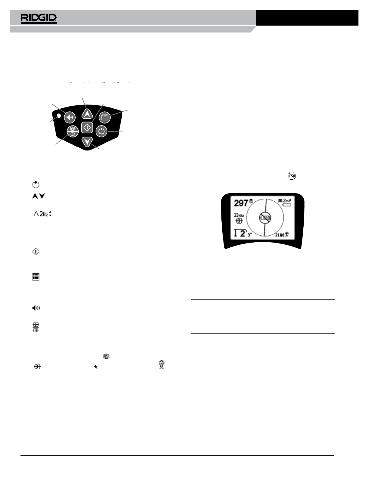
Figure 18:Line Trace Frequency Chosen
with the Frequency Key
(This screen will ash briey when a
new frequency is chosen)
2. Observe the Proximity Signal to ensure that the
receiver is picking up the transmitted signal. The
Proximity Signal should peak over the line and drop
o on either side.
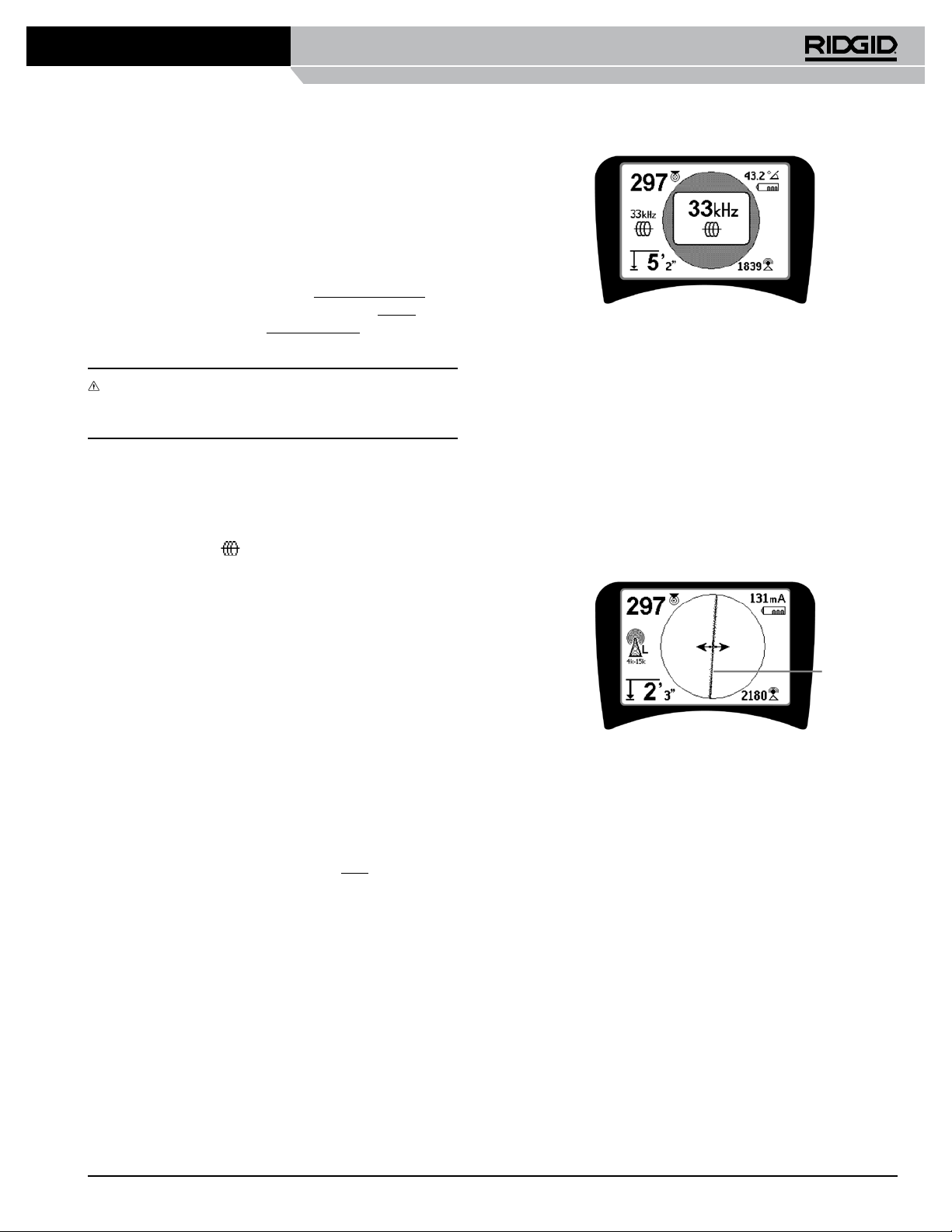
3. When tracing, the direction the pipe or cable is
running will be shown on the screen by theTracing
Line. The Tracing Line will be a clear, single line if the
eld being detected is undistorted.
Figure 19: Tracing Line Showing Low Distortion
4. If other elds are interfering in some way, the
distortion caused by those elds will be reected by
a blurring of the Tracing Line. This alerts the operator
that the apparent axis of the line may be inuenced
by other elds, and requires careful evaluation. The
more distorted the detected eld, the broader the
cloud around the Tracing Line will be.
The Tracing Line has three important functions.
It represents the location, and the direction, of the
signal being traced. It reects changes in direction
of the target utility — when the utility makes a turn,
for example. And it helps recognize signal distortion.
It does this by becoming cloudier as distortion
increases.
Tracing Line