Riele 4040+ User manual

Operating Instructions
Photometer 4040+
ROBERT RIELE GmbH & Co KG
Software Version 2.2
Documentation Version 08.2017
4040+e_22.docx / 06.10.17
ROBERT RIELE GmbH & Co KG Page 2 GENERAL NOTES
SYMBOLS
The packaging material, the type plate on the instrument and the manual may contain the following symbols or
abbreviations:
Manufactured by:
This product fulfills the requirements of Directive 98/79/EC on
in vitro diagnostic medical devices.
In vitro diagnostic medical device
Caution (refer to accompanying documents)!
Please refer to safety-related notes in the manual accompanying this device.
Please consult instructions for use
Symbol for the marking of important information for appropriate handling of the device
Biohazard
Samples containing material of human origin must be treated as potentially infectious.
The relevant laboratory guidelines on safe use must be observed.
Symbol for the marking of electrical and electronics devices according to § 7 ElektroG
IP XO
No special protection against penetrating moisture (IP = International Protection)
REF
Order number
SN
Serial number
INSTRUMENT APPROVALS
The Photometer 4040+meets the requirements of Directive 98/79/EC on in vitro diagnostic medical devices
(IVDD). Furthermore, the Photometer 4040+is manufactured according to the special safety requirements for IVD
medical devices stated in EN 61010.

4040+e_22.docx / 06.10.17
ROBERT RIELE GmbH & Co KG Page 3 GENERAL NOTES
SAFETY INFORMATION
Operator qualification
Only appropriately trained operators are qualified to operate the device.
Environmental conditions
The Photometer 4040+is approved for indoor use only.
For further environmental conditions see chapter 11.1.
Patient ambience
The Photometer 4040+may not be used in the patient ambience.
Electrical Safety
This device was examined and left the factory in perfect technical condition. To preserve this and protect safe and
faultless operation, the operator must follow the orders and remarks of this operating manual.
Connect the device to grounded power outlets only. All peripheral devices that are connected to the Photometer
4040+must comply with safety standard EN 60950. Before connecting read the documentation of the peripheral
devices.
Opening covers or removing parts of the instrument, except where this can be achieved manually without the use
of any tool, may expose voltage-carrying components. Connectors can be live, too. Never try to maintain or repair
an open instrument which is carrying voltage.
Repairs at the device including replacement of the Lithium battery may be carried out only by authorized specialist
staff. Through improper repairs the warranty extinguishes, and the operator can be heavily jeopardized.
If suspected the device can no longer be operated safely, turn it off and take steps to ensure that no one will
subsequently attempt to use it.
Electromagnetic waves
Devices that emit electromagnetic waves may affect measured data, or cause the Photometer 4040+to malfunc-
tion. Do not operate the following devices in the same room where the Photometer 4040+is installed: mobile
phone, transceiver, cordless phone, and other electrical devices that generate electromagnetic waves.
Reagents
Regarding reagents follow the safety as well as the operating instructions of the manufacturers.
Pay attention to the currently valid German “Gefahrstoffverordnung” (GefStoffV)!
Biological safety
Liquid waste is potentially biologically hazardous. Always wear gloves if handling those materials. Do not touch
parts of the device other than those specified. Consult the laboratory protocol for handling biohazardous materials.
Pay attention to the currently valid German “Biostoffverordnung” (BioStoffV)!
Spillings and cleaning
If a sample is spilled on the device, wipe up immediately and apply disinfectant.
Waste
Handle liquid waste properly, according to legislation on water pollution, and on the treatment of drainage and
waste matter.
4040+e_22.docx / 06.10.17
ROBERT RIELE GmbH & Co KG Page 4 GENERAL NOTES
MANUFACTURER’S WARRANTY
ROBERT RIELE GmbH & Co KG warrants Photometer 4040+against defects in material and workmanship.
For further information contact the local distributor.
WASTE MANAGEMENT NOTE
At the end of the life or utilization time the device and the accessories can be given back to the manufacturer with
costs for an environmental waste disposal. The previous professional decontamination has to be proved with a
certificate.
Address of the manufacturer:
ROBERT RIELE GmbH & Co KG
Kurfuerstenstrasse 75-79
D-13467 BERLIN
GERMANY
Phone: +49 (0)30 404 40 87
Fax: +49 (0)30 404 05 29
E-mail: [email protected]
www.riele.de
QUALITY MANAGEMENT SYSTEM
ROBERT RIELE GmbH & Co KG maintains a quality management system according to ISO 13485, certified by
mdc medical device certification GmbH.

4040+e_22.docx / 06.10.17
ROBERT RIELE GmbH & Co KG Page 5 CONTENTS
CONTENTS
1INTRODUCTION TO PHOTOMETER 4040+...............................................7
2INSTALLATION .............................................................................................8
2.1 DELIVERY ........................................................................................................................................ 8
2.2 PREPARATION FOR INSTALLATION............................................................................................ 8
2.3 INSTALLATION................................................................................................................................. 8
2.4 LOADING PRINTER PAPER .......................................................................................................... 9
3OPERATING ELEMENTS...........................................................................10
3.1 FRONT............................................................................................................................................ 10
3.2 BACK .............................................................................................................................................. 10
3.3 TOUCHSCREEN............................................................................................................................. 11
3.4 WORKING AREA........................................................................................................................... 11
3.5 CUVETTE COMPARTMENT .......................................................................................................... 11
3.5.1 Working with standard cuvettes.............................................................................................. 11
3.5.2 Reducing the minimum measuring volume............................................................................. 11
4PROGRAM SELECTION IN MODUS 1.......................................................12
4.1 Measurement with programmed methods....................................................................................... 12
4.2 Measurement with basic methods................................................................................................... 13
4.3 Method editor.................................................................................................................................. 13
4.4 Utility programs ............................................................................................................................... 14
4.5 Line feed [LF].................................................................................................................................. 14
5OPERATION IN MODUS 2...........................................................................15
6CALCULATION PROCEDURES.................................................................17
6.1 GENERAL NOTES......................................................................................................................... 17
6.1.1 Fundamental to the handling ... .............................................................................................. 17
6.1.2 Fundamental to the tempering ............................................................................................... 17
6.1.3 Fundamental to the inputs ... .................................................................................................. 17
6.1.4 Fundamental to the methods with standard ........................................................................... 18
6.1.5 Fundamental to the methods with multi-standards ... ............................................................. 18
6.1.6 Fundamental to bichromatic measurements … ...................................................................... 18
6.1.7 Fundamental to the Kinetic….................................................................................................. 19
6.1.8 Fundamental to the methods with reagent blank…................................................................. 22
6.1.9 Fundamental to ID-NO. and sample numerator… .................................................................. 22
6.1.10 Fundamental to storing test results… ..................................................................................... 22
6.2 ABBREVIATIONS ........................................................................................................................... 23
6.3 SURVEY OF THE METHODS ..................................................................................................... 24
6.4 DESCRIPTION OF METHOD PROCEDURES............................................................................ 25
6.4.1 Calculation procedure 1 (C/F)................................................................................................. 26
6.4.2 Calculation procedure 2 (C/F/Rb) ........................................................................................... 27
6.4.3 Calculation procedure 3 (C/F/Sb) ........................................................................................... 28
6.4.4 Calculation procedure 4 (C/F/SbRb)....................................................................................... 29
6.4.5 Calculation procedure 5 (C/S)................................................................................................. 30
6.4.6 Calculation procedure 6 (C/S/Rb)........................................................................................... 31
6.4.7 Calculation procedure 7 (C/S/Sb) ........................................................................................... 32
6.4.8 Calculation procedure 8 (C/S/SbRb)....................................................................................... 33
6.4.9 Calculation procedure 9 (FTK/F/Rb)....................................................................................... 34
6.4.10 Calculation procedure 10 (FTK/S/Rb)..................................................................................... 35
6.4.11 Calculation procedure 11 (KIN/F/Rb)...................................................................................... 36
6.4.12 Calculation procedure 12 (KIN/S/Rb)...................................................................................... 37
6.4.13 Calculation procedure 13 (TRANSMISSION) ......................................................................... 38
6.4.14 Calculation procedure 14 (C/F Delta)...................................................................................... 39
6.4.15 Calculation Procedure 15 (C/F 3 WL)..................................................................................... 41
6.4.16 Calculation Procedure 16 (DELTA R1R2)............................................................................... 42
7METHOD EDITOR.......................................................................................44

4040+e_22.docx / 06.10.17
ROBERT RIELE GmbH & Co KG Page 6 CONTENTS
8UTILITY PROGRAMS.................................................................................47
8.1SELECTION OF UTILITY PROGRAMS....................................................................................... 47
8.2 DESCRIPTION OF UTILITY PROGRAMS................................................................................... 48
8.2.1 Optic adjustment..................................................................................................................... 48
8.2.2 Multi-standard functions.......................................................................................................... 49
8.2.3 Printer ON / OFF..................................................................................................................... 50
8.2.4 Bar Code................................................................................................................................. 51
8.2.5 Menu serial COM.................................................................................................................... 51
8.2.6 Quality control......................................................................................................................... 52
8.2.7 Settings printout...................................................................................................................... 56
8.2.8 Stored results.......................................................................................................................... 57
8.2.9 Heating ON / OFF................................................................................................................... 57
8.2.10 Laboratory name..................................................................................................................... 57
8.2.11 User name.............................................................................................................................. 58
8.2.12 Error list .................................................................................................................................. 58
8.2.13 Key signal ON / OFF............................................................................................................... 58
8.2.14 Touchscreen adjustment......................................................................................................... 59
8.2.15 Date / Time............................................................................................................................. 60
8.2.16 Language................................................................................................................................ 60
8.2.17 ADC counts (Optic)................................................................................................................. 61
8.2.18 Service tools........................................................................................................................... 61
9MAINTENANCE ...........................................................................................62
9.1 CLEANING INSTRUCTION ........................................................................................................... 62
9.2 CALIBRATING MEASURING SYSTEM........................................................................................ 62
9.3 REPLACEMENT OF PAPER ROLL............................................................................................. 62
9.4 REPLACEMENT OF LINE FUSES............................................................................................... 63
10 ERROR MESSAGE / CORRECTION..........................................................64
10.1 GENERAL NOTE........................................................................................................................... 64
10.2 ACOUSTIC ERROR MESSAGES................................................................................................. 64
10.3 PLAINTEXT ERROR MESSAGES................................................................................................ 64
10.4 CODED ERROR MESSAGES ...................................................................................................... 64
11 TECHNICAL DATA.....................................................................................67
11.1 ENVIRONMENTAL CONDITIONS................................................................................................. 67
11.2 MINIMAL OPERATION QUALITY................................................................................................. 67
11.3 TYPE PLATE ................................................................................................................................. 67
11.4 SHORT SPECIFICATIONS............................................................................................................ 68
11.5 TECHNICAL SPECIFICATIONS..................................................................................................... 69
12 ACCESSORIES AND SPARE PARTS.......................................................71
13 METHOD LIST ............................................................................................72
13.1 BASIC METHODS.......................................................................................................................... 72
13.2 LIST OF USER SPECIFIC METHODS ....................................................................................... 73

4040+e_22.docx / 06.10.17
ROBERT RIELE GmbH & Co KG Page 7 1 - INTRODUCTION TO PHOTOMETER 4040
1 INTRODUCTION TO PHOTOMETER 4040+
This device is a programmable photometer for manual applications. It is designed for In Vitro Diagnostic (IVD)
and to be used by qualified laboratory staff.
It is operated via touchscreen. Remote control is possible by a serial data interface (chapter 8.2.5 - Menu serial
COM –REMOTE CONTROL).
The device is useable e.g. for wet clinical-chemical analyses. The solution can be measured in glass or disposable
cuvettes.
The optical compartment allows to measure four analyses at the same time. Three channels (1-3) are reserved
to perform kinetic measurements at 340nm. The fourth channel (F) allows performing tests in the visibile range
due to an integrated filter wheel.
The Photometer 4040+can be operated in two different modi:
Modus 1 is working similar to the Photometer 4040. Measurements at 340nm are perfomed in channel 2 and the
visual range in channel F.
Modus 2 is the four channel modus. Here the display is devided into four section showing results of all four
channels.
If required, the minimum measuring volume of 500 µl can be reduced to 250 µl (chapter 3.5.2 - Reducing the
minimum measuring volume)
The solution is quickly and exactly heated to 37 °C in the measuring cells. An external dry incubator (e.g. T20)
can be attached to the Photometer 4040+.
For measuring methods several programmed methods with open parameters are available (chapter 6 -
CALCULATION PROCEDURES and chapter 13 - METHOD LIST).
Besides, up to 231 methods - built up on the basic methods - can be established and stored by the operator with
a method editor. A list of methods can be printed out (chapter 7 - METHOD EDITOR).
In modus 1 up to 50 nonlinear calibration curves with maximum 20 sets of points can be stored (chapter 8.2.2 -
Multi-standard functions).
The Photometer 4040+is standard equipped with six optical filters of the wavelengths 340 (channels 1-3), 405,
492, 546, 578 and 623 nm (channel F). If required, they can be exchanged against any wavelength within the
range of 405-730 nm. Three additional filters, e.g. 670 nm, can be installed.
The device is equipped with a thermal printer.
The measuring data can be stored and managed in the Photometer 4040+(chapter 8.2.8 - Stored results).
According to a GLP conformal documentation the names of lab and operator can be printed out as well as
transferred to EDP (chapter 8.2.5 - Menu serial COM –EDP ON/OFF).
In modus 1 in Photometer 4040+up to 50 methods can be supervised with a quality control.(chapter 8.2.6 - Quality
control).
Numerous utility programs permit the individual configuration of the device. Function tests support the analysis of
sources of error.
Photometer 4040+is future-proof by FLASH MEMORY technology: The operating system can be updated with
program novelties and/or improvements comfortably, without having to open the equipment (please ask distributor
for further information).

4040+e_22.docx / 06.10.17
ROBERT RIELE GmbH & Co KG Page 8 2 - INSTALLATION
2 INSTALLATION
2.1 DELIVERY
Check the device and contents of the enclosed box as follows on visible transport damages and completeness:
1 Operator’s Manual
1 Dust cover
2 Fuses for line power
1 Mains cable
2 Thermal printer paper
1 Top cover small for printer
Inform the sales office immediately about transport damages. Keep the original packaging for a possible
return.
2.2 PREPARATION FOR INSTALLATION
Place the device on a stable, level surface. Do not obstruct the input air at the bottom and the waste air at the
back plate to guarantee the ventilation of the device.
If the device was exposed to extraordinary fluctuation in temperature and/or humidity, it must acclimatize suffi-
ciently before operation.
2.3 INSTALLATION
Photometer 4040+operates at any line voltage between 100 VAC and 240 VAC at 50/60 Hz. The device plug of the
mains cable must be put into the socket at the back of the device and the mains plug into a grounded mains
socket.
While connecting or disconnecting an external device (PC, printer) to Photometer 4040+both devices must
be switched off.
Switch on Photometer 4040+by the mains switch at the back.
Greeting screen:
After switching on copyright, website, type of
device and version designation are
displayed and - in the case of activated
printer - printed out.
( c ) R O B E R T R I E L E
G m b H & C o K G
P H O T O M E T E R 4 0 4 0 +
V2. 2 a d d / m m / y y D
w w w . r i e l e . d e

4040+e_22.docx / 06.10.17
ROBERT RIELE GmbH & Co KG Page 9 2 - INSTALLATION
After around 15minutes the device is heated
up and ready for measurement.
First the tempering is switched off. If working
with tempered material is required later,
switch on the tempering already now either
directly by the utility program (chapter 8.2.9
- Heating ON / OFF) or indirectly by selec-
tion of a method with programmed
tempering (chapter 6.1 - GENERAL
NOTES).
If errors appeared during operation, first of all they have to be confirmed with [E] before remedy (chapter 10 -
ERROR MESSAGE / CORRECTION).
2.4 LOADING PRINTER PAPER
With initial operation or if the colored end of the paper roll appears, printer paper must be inserted:
Open the printer cover.
Put the green head-up lever in the up position.
Remove the rest of paper.
Put the green head-up lever in the down position.
Put printer paper axis into the new printer paper reel.
Insert the paper inside the printer. The roller will automatically feed the paper for about 4 cm.
Press [LF] several times for line-feed until the paper has a length of about 5 cm. In case of no reaction
the printer may be deactivated.
Insert printer paper reel into the axis guide.
Push the printer paper through the slot in the printer cover and close the printer with the cover.

4040+e_22.docx / 06.10.17
ROBERT RIELE GmbH & Co KG Page 11 3 - OPERATING ELEMENTS
3.3 TOUCHSCREEN
The touchscreen shows applications and
information. It is contact-sensitive and reacts
to the pressure exerted on it. In order to
execute a function, the desired range on the
screen must be touched
The surface of the touchscreen may
be never touched with ball-point pen, pencil
or another pointed article!
3.4 WORKING AREA
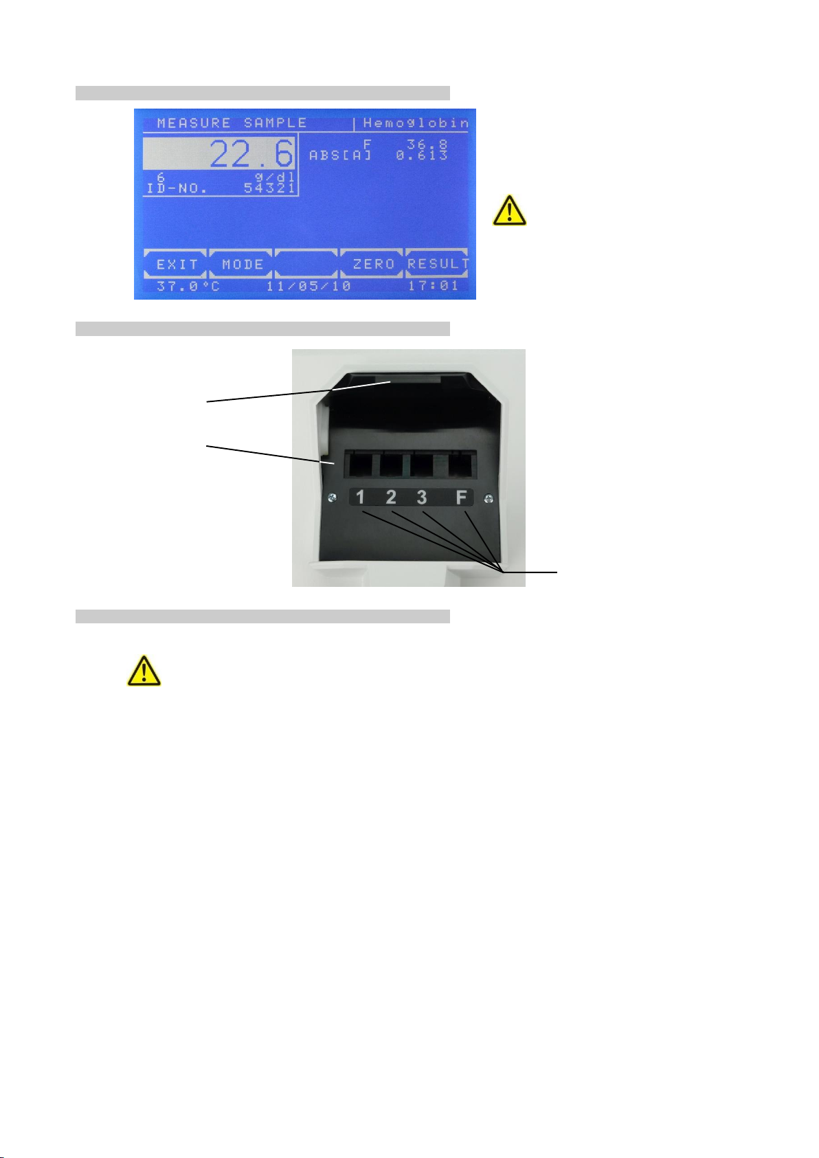
3.5 CUVETTE COMPARTMENT
3.5.1 Working with standard cuvettes
The optical path is directed from the back to the front of the device. Insert single cuvette according to the
drawing OPTIC CONSTRUCTION in TECHNICAL DATA.
Trigger setting to zero by [ZERO].
Trigger a normal measuring by [RESULT].
3.5.2 Reducing the minimum measuring volume
The minimum measuring volume can be reduced from 500 µl to 250 µl.
Spacers can be inserted into the measuring cells.
lid
working area
measuring cell
channels 1-3 for 340 nm
channel F for the visible range
4040+e_22.docx / 06.10.17
ROBERT RIELE GmbH & Co KG Page 12 4 - PROGRAM SELECTION
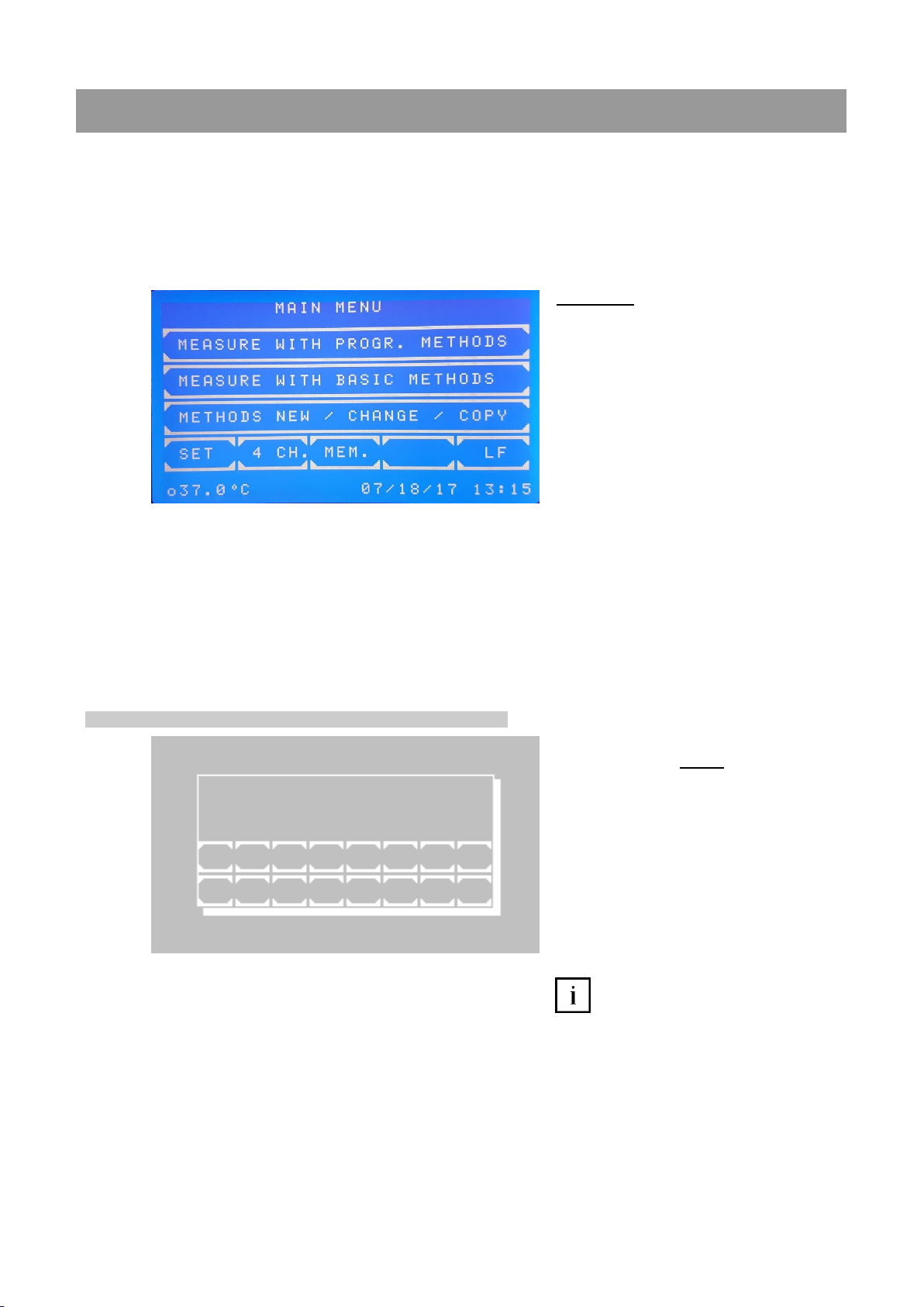
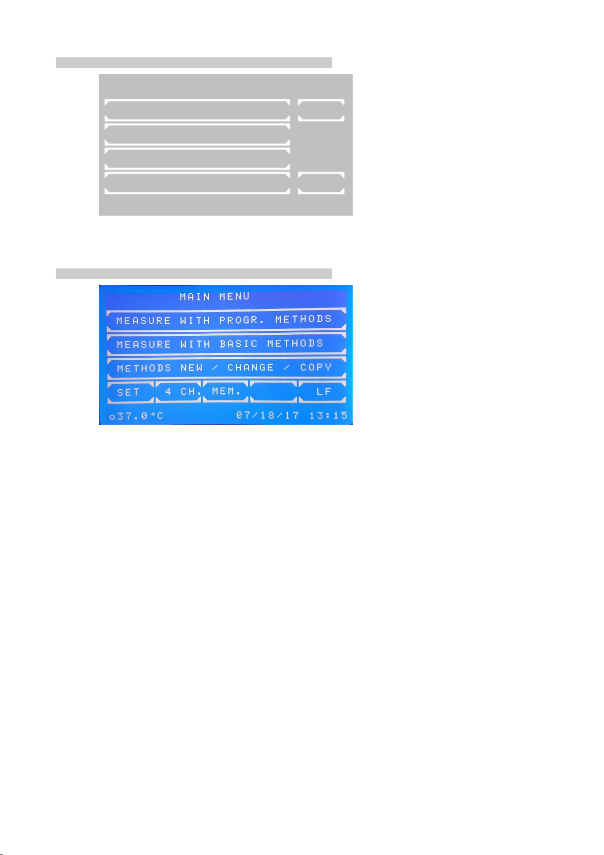
4 PROGRAM SELECTION IN MODUS 1
After switch-on the touchscreen shows the main menu.
From this screen the basic methods (unalterably programmed in the system) or operator specific programmed
methods can be reached similar to the usage of Photometer 4040. This modus is called Modus 1 in the following.
Also the adjusting programs are started from this mask. With the method editor own methods can be established
and changed. The utility programs cover theconfiguration adjustments andcheck routines.The line feed of printer
by [LF]. The four channel modus is reched by [ 4 CH.] decribed further in chapter 5 - OPERATION IN MODUS 2.
After completion of a method or execution of a utility program the program always returns to the main menu.
Main menu:
Down in the status line from left to right
following is shown:
Current temperature of the cuvette
compartment in °C. The temperature of
the optical compartment is displayed as
o37.0°C and of an optional attached
incubator i37.0°C
In the case of switched off tempering the
temperatures are not displayed.
In the case of switched on tempering and
instable temperature the display
changes between --.--C and e.g. 37.3°C.
In the case of stable temperature the
current temperature of e.g. 37.0°C is
shown. Small fluctuations of the value
are normal.
Date in the format day/month/year
Time
4.1 Measurement with programmed methods
A programmed method for a photometric
test can be called directly by input of the
method number.
The valid range for a method number lies
between 20 and 250.
Scroll all existing methods by [+] or [-]. If no
method is programmed, a plain text error
message (chapter 10.3 - PLAINTEXT
ERROR MESSAGES) is shown.
Call the selected method by [E].
Return to main menu by [ESC].
A programmed method can be estab-
lished via menu METHOD NEW /CHANGE /
COPY (chapter 4.3 - Method editor).
The transmission of a method collection is
possible by PC with special software.
Further information:
Application sheets of reagent manufacturers
M E T H O D S N O . 30
M E T H O D : G l u c o s e
U N I T : m g / d l
1 2 3 4 5 6 7 8
E S C 9 0 . + - E

4040+e_22.docx / 06.10.17
ROBERT RIELE GmbH & Co KG Page 13 4 - PROGRAM SELECTION
4.2 Measurement with basic methods
A photometric test can be executed by a method already permanently programmed, but open in all setting
parameters. 14 different methods with different calculation procedures are available. Each of these methods can
serve as prototype for a method programmed by the operator.
Available are:
Absorbance measurement
Concentration measurement / end point
measurement
Fixed time kinetic / two point kinetic
Kinetic
Transmission
Scrolling through all methods is possible by
[PAGE]. The current page is shown at the
right upper screen corner. By [END] the
program returns to the main menu.
A method is selected by pressing the corre-
sponding key.
The following abbreviations are used for the
distinction of the methods:
CONC. = concentration
KIN = kinetic
FTK = fixed time kinetic
F = factor
STD = standard
RB = reagent blank
SB = sample blank
Further information:
Chapter: 6 - CALCULATION
PROCEDURES
4.3 Method editor
Each photometric test can be permanently
stored with its setting parameters by the
method editor.
With the functions of the method editor are
possible the new installation, the change
and removing a method.
By [LIST] an overview of the programmed
methods can be printed and transmitted via
the serial interface.
Further information:
Chapter: 7 - METHOD EDITOR
B A S I C M E T H O D S P A G E 1 / 4
C O N C . W . F A C T O R P A G E
C O N C . W . F A C T O R R B
C O N C . W . F A C T O R S B
C O N C . W . F A C T O R R B S B E X I T
M E T H O D N E W / C H A N G E / C O P Y
M E T H O D C O P Y L I S T
M E T H O D E D I T
M E T H O D N E W
M E T H O D D E L E T E E X I T
o37.0°Ci37.0°C07/24/2017 10:14
4040+e_22.docx / 06.10.17
ROBERT RIELE GmbH & Co KG Page 14 4 - PROGRAM SELECTION
4.4 Utility programs
Utility programs (push [SET]) are necessary
for the adjustment and maintenance of
Photometers 4040+.
Further information:
Chapter: 8 - UTILITY PROGRAMS
4.5 Line feed [LF]
Pressing [LF] in the main menu triggers a
line feed in the case of activated printer.
Several lines can be advanced by
continuous pressure on [LF].
U T I L I T I E S P A G E 1 / 5
O P T I C A D J U S T M E N T P A G E
M U L T I - S T A N D A R D
P R I N T E R
B A R C O D E E X I T
o37.0°Ci37.0°C07/24/2017 10:14

4040+e_22.docx / 06.10.17
ROBERT RIELE GmbH & Co KG Page 15 4 - PROGRAM SELECTION
5 OPERATION IN MODUS 2
The four channel modus (modus 2) can be reached via [4 CH.] in the Main Menu. Methods used in the modus 2
must be preprogrammed in the method editor. Hereby, 14s is a fixed interval between two measurements.
Therefore, only multiples of 14s are possible for time settings.
For every channel a method can be
selected separately. For channels 1M –3M
methods measured at 340 nm may be
selected. FM is for tests in the visible
range.
Measurement with programmed
methodsin modus 2:
Three channels #1-3 for Kinetic, e.g. ALT1,
ALT2 and ALT3 and one (#F) for end point
measurement (e.g. Hb) are displayed.
The current position of the reading unit is
underlaid with a white background. Here, at
position #3 the result is currently measured.
Push [ESC] to exit the four channel modus.
By pushing [BC] either a barcode may be
read when a barcode reader is connected
(the barcode is underlaid with a white
background)
or
a barcode is generated in the format:
YYMMDD0000001 including the
year/month/day (YYMMDD). For example
sample No. 7 has the ID number
1601150000007.
When [BC] was not pushed the results are
not saved to the memory.
[Z] A zero measurement needs to be done at
the beginning of the first measurement.
When activated the button is underlaid with
a white background. All channels may be
selected at the same time. The
measurement is performed when the motor
has reached the respective position.
When the [Z] button returns toblue the result
button [R] may be pushed.

4040+e_22.docx / 06.10.17
ROBERT RIELE GmbH & Co KG Page 16 4 - PROGRAM SELECTION
All measurements may be performed
simultaneaously.
As long as the [R] has a white background
the measurement is carried out.
The first line of every channel shows the
current action, e.g.
INCUBATION, E2 or 1, etc..
When the measurement is finished the result
is displayed in combination with the
dimension, i.e. -43 U/L ALT3.
The 2nd row shows the method name and the
r^2 (e.g. 0.9808)
When pushing [ESC] the measurements are
interrupted and the following window is
reached:
[ESC] terminates the four channel modus 2.
[M] returns to the measurements.
Interrupted measurements are continued.
However, original reaction times are not
valid anymore.
With [P1], [P2] and [P3] more details of the
tests in channels #1-3 may be shown.
The progress of the kinetic is shown after a
few seconds.
The axis of time is marked by [s], the axis of
extinction is marked by [ABS]
The currently used FACTOR and the
calculated DELTA REG are shown in the
bottom lines.
If R^2 is activated, the term LINEAR or NON-
LINEAR is shown in the upper right corner.
By [PRINT] a graphical printout is generated.
By [LIST] all data points are shown
sequentially.

4040+e_22.docx / 06.10.17
ROBERT RIELE GmbH & Co KG Page 17 6 - CALCULATION PROCEDURES
6 CALCULATION PROCEDURES
6.1 GENERAL NOTES
The device offers operator guidance in the display by a combination of plaintext and short terms.
Messages and inputs regarding the method always have to be confirmed by [OK]. By [EXIT] all methods can be
broken off. For a restart see chapter 4 - PROGRAM SELECTION. Measuring is generally triggered by [RESULT],
zero measuring by [ZERO].
6.1.1 Fundamental to the handling ...
Before measuring with standard cuvettes the lid of the cuvette compartment is to be closed.
Deviations from normal operation, caused by the device or by the operator, are notified by
“ERROR”. They always have to be confirmed by [E] (chapter 10 - ERROR MESSAGE / CORRECTION).
Example: The reading exceeds the programmed upper limit.
6.1.2 Fundamental to the tempering ...
Tempering switched on or off is parameter of a method.
After switching on the tempering it lasts up to 15 minutes until a constant temperature of 37 °C is reached.
The current temperature of the cuvette is shown at the Iower edge of the touchscreen. For meaning of
the display see chapter 4 - PROGRAM SELECTION /MAIN MENU. A temperature instable or out of
tolerance during measuring is marked by an asterisk (*) at the utmost right position in the corresponding
print line.
To avoid deviations due to temperature influence a delay between triggering and actual measuring can
be programmed in each method.
For a quick mode of operation all temperature-sensitive samples, reagents and washing solutions should
be externally tempered by Incubator T12/T16 (REF 500-002 / 500-001) or a water bath.
6.1.3 Fundamental to the inputs ...
The input format of the factor and/or the standard with sign determines the output format of the result
concerning the number of decimal places.
Example: With factor “36.8” the calculated concentration will be shown with one decimal place.
Each factor or standard can be minus signed, so that the result is calculated with correct sign.
Example: The test GOT is programmed with the factor “-1746“ because the measuring principle implies
a decreasing absorbance.
For a homogeneous solution the input of a delay before a measuring is possible at all methods.
All delay times can be aborted by pressing the touchscreen at any place for a long time.

4040+e_22.docx / 06.10.17
ROBERT RIELE GmbH & Co KG Page 18 6 - CALCULATION PROCEDURES
6.1.4 Fundamental to the methods with standard ...
Each measuring of a standard (calibrator) can be executed as single, double or triple determination.
Following is shown:
In the white reading window the
averaged absorbance of the
standard is shown.
Below the white reading window
the absorbance 1, 2 and 3 of a
standard are shown.
By [OK] the average of all values is
taken over. Values with 0 are
ignored and excluded from the
calculation. The resulting factor is
calculated from the average of the
standard.
By [CURS.] a value is selected. A
flashing white square marks the
current value.
By [DEL.] a value is deleted and
excluded from the calculation.
By [RESULT] a measuring is
triggered.
The determined resulting factor of a standard measurement is stored together with the corresponding
method number. After renewed selection of this method the last resulting factor is offered as "OLD STD".
The principle of the multiple measurement can also be expanded to all measurements. The correspond-
ing entry can be set invoking a basic method. The parameter is definable in preprogrammed methods
(chapter 7 - METHOD EDITOR).
6.1.5 Fundamental to the methods with multi-standards ...
Linear calibration is used in the case of two calibrators. The absorbance forms a linear diagram with the
concentrations (chapter 8.2.2 - Multi-standard functions).
Nonlinear calibration is used for samples with a nonlinear but reproducible connection between the
absorbance and the concentrations. At least three (maximum 20) calibrators are required for nonlinear
calibration (chapter 8.2.2 - Multi-standard functions).
6.1.6 Fundamental to bichromatic measurements …
The calculation procedures based on endpoint measurement (CP 1 to CP 8, CP 13 and CP 14) can be
executed bichromatic. The zero measurement will be done with a wavelength defined as bichromatic.
The bichromatic wavelength might be not included in the standard set of filters. The bichromatic
wavelength can be set after calling a method (chapter 6 METHOD EDITOR Fig. 6.5).
M E A S U R E S T G l u c o s e
S T [ A ]
0 . 6 1 6
0 . 6 1 2
0 . 6 1 7
O K C U R S . D E L . R E S U L T
o37.0°Ci37.0°C07/24/2017 10:14
0.615

4040+e_22.docx / 06.10.17
ROBERT RIELE GmbH & Co KG Page 19 6 - CALCULATION PROCEDURES
6.1.7 Fundamental to the Kinetic…
In a kinetic method the sample absorbance is measured several times in pre-established time intervals.
The user can define a delay time and a quantity and duration of time intervals after the delay time (Deltas or Δt).
At the beginning and at the end of the delay time the absorbance values ABS.1 and ABS.2 are measured
respectively. The difference |ABS.1 –ABS.2| allows the differentiation between normal and abnormal activities.
This is followed by a sequence of measurements in regular time intervals (Deltas or Δt). An example of a resulting
curve is shown in Fig. 5.1.7.1:
Fig. 6.1.7.1: Resulting curve of kinetic test, decreasing absorbance
In each time interval (Delta or Δt) the difference between the relating absorbance values as well as the gradient
of the curve are calculated.
To obtain the alteration per minute AS,Minute the gradients must be averaged. This is done by a simple linear
regression calculation also giving an indicator for the linearity of the test. This indicator is called the coefficient of
correlation R. For practical reasons, the square of the coefficient of correlation R^2 or coefficient of determination
is taken in a Kinetic calculation. The value of R^2 can vary between 0 and 1. An R^2 value of 1 indicates perfect
linearity and a value of 0 indicates absolute non-linearity. Already values < 0.9 indicate a bad linearity and
therefore an incorrect test. In order to improve the linearity of the kinetic only the best three deltas are considered
in the calculation procedure of the regression calculation. Therefore, at least three deltas are required when
programming a new method. If this procedure does not lead to an improvement all deltas are reconsidered in the
calculation procedure.
In practice, linear tests show values of R^2 near to 1. In the example for Calculation procedure 11 (KIN/F/Rb)
values of R^2 ≥0.998 are permitted. Results with smaller R^2 values could be caused by temperature instability,
pollution, expired reagents, unfavorable delay time, etc.
For a better monitoring the number of deltas (deltas or Δt) should be bigger than specified for the manual
procedure. The classic three-minutes-test with three deltas of 60 s can be replaced by 15 deltas of 12s.
When programming a new method, which is based on CP 11 or CP 12, it is possible to set lower and upper limits
for the measurement result within the method editor (see chapter 7 - METHOD EDITOR, Fig. 6.5). This can be
achieved setting the parameters MIN. VALUE and MAX. VALUE. If the measured value exceeds the MAX. VALUE
a message RANGE MAX. is shown and if the measured value falls below MIN. VALUE message RANGE MIN. is
shown. Also a lower limit for R^2 can be entered by setting MIN. R^2, if the obtained R^2 value falls below the
entered value a message NON-LINEAR is shown.
In order to get positive results at tests with decreasing absorbance (see Fig. 5.1.7.1), a negative factor has to be
entered. Only if MAX. VALUE is set and the sign of the measured value is not equal to the sign of the entered
MAX. VALUE a message RANGE +/- is shown.
The parameters MIN. VALUE, MAX. VALUE and MIN. R^2 are deactivated entering a zero value.

4040+e_22.docx / 06.10.17
ROBERT RIELE GmbH & Co KG Page 20 6 - CALCULATION PROCEDURES
Presentation of the results on the display after a successful measurement:
View after the successful measurement
By [DiAG] the progress of the kinetic is shown.
View after confirming by [MODE].
View after pressing [MODE] [MODE]
By [PRN] the internal printer is switched off.
By [DETAIL] all immediate test results are
shown or printed.
By [ZERO] the zero measurement is repeated.
The measurement is repeated by [RETRY].
View after pressing [DIAG.]
The progress of the kinetic is shown after a few
seconds.
The axis of time is marked by [s], the axis of
extinction is marked by [ABS]
The currently used FACTOR and the calculated
DELTA REG are shown in the bottom lines.
If R^2 is activated, the term LINEAR or NON-
LINEAR is shown in the upper right corner. By
[PRINT] a graphical printout is generated. By
[LIST] all data points are shown sequentially.
Sequential View of data points after confirming
[DIAG] and [LIST]
By [NEXT] for each data point the numeration
the time [s] and the extinction is shown.
Table of contents
Other Riele Measuring Instrument manuals


Popular Measuring Instrument manuals by other brands


Omega
Omega PLATINUM Series user guide

Rohde & Schwarz
Rohde & Schwarz UD1065 Getting started

Xylem
Xylem SI Analytics Lab 865 quick start guide

Agilent Technologies
Agilent Technologies U3025AE10 user guide

Cellbox
Cellbox Flight CDI Technical manual

Hanna Instruments
Hanna Instruments HALO2 HI9810382 instruction manual


