Riele Photometer 5010 User manual

Photometer 5010
Version 4.x
upwards serial no. 5000
Service Manual

CONTENTS
chapter headline page file
RIELE BERLIN Photometer 5010 / V4 1 11.05.2004
1 General notes Sm_V4_a.pdf
1.1 Contact partner 1.1 Sm_V4_a.pdf
1.2 Proved security 1.1 Sm_V4_a.pdf
1.3 Precautions and hazards 1.2 Sm_V4_a.pdf
2 Service concepts Sm_V4_a.pdf
2.1 Service level 2.1 Sm_V4_a.pdf
2.2 Conditions 2.2 Sm_V4_a.pdf
3.1 Block diagram 3.1.1 Sm_V4_a.pdf
3.2 Short instruction guide 3.2.1 Sm_V4_a.pdf
3.3 Service tools 3.3.1 Sm_V4_a.pdf
3.4 Plug identification 3.4.1 Sm_V4_a.pdf
4.1 Mains power circuit 4.1 Sm_V4_b.pdf
4.2 Mains connector 4.2 Sm_V4_b.pdf
4.3 AC / DC power supply 4.3 Sm_V4_b.pdf
4.10 Optical unit 4.10.1 Sm_V4_b.pdf
4.11 Filter wheel 4.11.1 Sm_V4_b.pdf
4.12 Halogen lamp 4.12.1 Sm_V4_b.pdf
4.13 Photodiode with plug 4.13.1 Sm_V4_b.pdf
4.14 Heating unit 4.14.1 Sm_V4_b.pdf
4.15 Peltier element 4.15.1 Sm_V4_b.pdf
4.16 Pump motor 4.16.1 Sm_V4_b.pdf
4.17 Tooth belt 4.17.1 Sm_V4_b.pdf
4.18 Step motor filter wheel 4.18.1 Sm_V4_b.pdf
4.19 Light barrier filter wheel 4.19.1 Sm_V4_b.pdf
4.20 Bubble detector 4.20.1 Sm_V4_b.pdf
4.21 Flow-through cuvette adaptor 4.21.1 Sm_V4_b.pdf
4.22 Standard cuvette adaptor 4.22.1 Sm_V4_b.pdf
4.23 Connector bubble detector 4.23.1 Sm_V4_b.pdf
4.24 Lamp holder 4.24.1 Sm_V4_b.pdf
4.25 Cuvette lense kit 4.25.1 Sm_V4_b.pdf
4.26 Tubes 4.26.1 Sm_V4_c.pdf

CONTENTS
chapter headline page file
RIELE BERLIN Photometer 5010 / V4 2 11.05.2004
4.30 Top case 4.30.1 Sm_V4_c.pdf
4.31 Display glass 4.31.1 Sm_V4_c.pdf
4.32 Metal tube inlet 4.32.1 Sm_V4_c.pdf
4.33 Micro switch 4.33.1 Sm_V4_c.pdf
4.34 Keyboard 4.34.1 Sm_V4_c.pdf
4.35 Printer mechanism 4.35.1 Sm_V4_c.pdf
4.40 Mother board RR_115 Sm_V4_d.pdf
General description 4.40.1 Sm_V4_d.pdf
Component diagram 4.40.2 Sm_V4_d.pdf
Voltages 4.40.3 Sm_V4_d.pdf
Voltage 12 VDC of halogen lamp 4.40.4 Sm_V4_d.pdf
Fuses F1, F2 and F3 4.40.4 Sm_V4_d.pdf
Amplifier of photocurrent and ADC 4.40.5 Sm_V4_d.pdf
Adjustment of amplifier stage 4.40.6 Sm_V4_d.pdf
Contrast of LCD 4.40.7 Sm_V4_d.pdf
Temperature control 4.40.8 Sm_V4_d.pdf
Adjustment of temperature control 4.40.9 Sm_V4_d.pdf
Thermal adjustment 4.40.10 Sm_V4_d.pdf
Installation instruction 4.40.11 Sm_V4_d.pdf
Circuit diagrams 4.40.13 Sm_V4_e.pdf
Circuit diagrams 4.40.17 Sm_V4_f.pdf
4.42 Display unit pcb RR_114 or pcb RR_119 4.42.1 Sm_V4_g.pdf
4.43 Cuvette connection pcb RR-103-V4 4.43.1 Sm_V4_g.pdf
4.44 Printer controller pcb 4.44.1 Sm_V4_g.pdf
4.50 Fan 4.50.1 Sm_V4_g.pdf
4.51 Bottom case 4.51.1 Sm_V4_g.pdf
4.52 Carton Photometer 5010 4.52.1 Sm_V4_g.pdf
5 Mantling / Dismantling Sm_V4_h.pdf

CONTENTS
chapter headline page file
RIELE BERLIN Photometer 5010 / V4 3 11.05.2004
6.1 Communication protocol 6.1 Sm_V4_h.pdf
6.2 Exchange of EPROM 6.6 Sm_V4_h.pdf
6.3 DOS: Download to FLASH MEMORY 6.7 Sm_V4_h.pdf
6.4 WINDOWS: Resume after malfunction 6.9 Sm_V4_h.pdf
6.5 Initialization of bootstrap 6.12 Sm_V4_h.pdf
7 Trouble shooting 7.1 Sm_V4_h.pdf
8 Spare parts 8.1 Sm_V4_h.pdf
9.1 Calibration procedure of Photometer 5010
Subject: Cuvette temperature 9.1.1 Sm_V4_h.pdf

1 GENERAL NOTES
RIELE BERLIN Photometer 5010 / V4 1.1 20.08.2003
The data and information provided in this manual correspond to the state of knowledge existing at
the time of introducing the Photometer 5010 on the market. Any important changes will be taken
into account in the next edition of this manual.
In any case, the respective packaging leaflet should be regarded as authoritative.
This service manual was created for the telephone service and technical service staff.
1.1 Contact Partner
Technical product management and support:
ROBERT RIELE GmbH & Co KG
Address: Kurfürstenstraße 75 - 79
D - 13467 Berlin
Germany
Phone: ++49 / 30 / 404 40 87
Fax: ++49 / 30 / 404 05 29
1.2 Proved Security
This instrument has been constructed under the regulations of EN 61010-1:1993 and
EN 61010-1/A2:1995.
This device was examined and left the factory in perfect technical condition. To preserve this and
protect safe and faultless operation, the user must follow the orders and remarks of this service
manual.
To preserve this condition and to guarantee a safe working, informations and working advices,
which are included in this working instructions, have to be heeded by the applier.
This instruments meets protection 1 (earth conductor wire).
1.3 Precaution and Hazards
All electrical equipment is potentially hazardous. Never remove covers without first ensuring that it
is isolated from the AC supply, unless specific maintenance instructions or repairs are being carried
out by authorized ROBERT RIELE personnel.
The hard- and software is subject to a program of continuos evaluation and improvement and,
therefore, may be changed in the future. This also concerns service requirements.
All samples and reagents should be treated with caution accorded to those known to contain
pathogenic organisms. Similarly, the cleaning of component part of Photometer 5010 should be
done with respect to human health.

1 GENERAL NOTES
RIELE BERLIN Photometer 5010 / V4 1.2 20.08.2003
Warning: All components used on Photometer 5010 must be regarded as potentially dangerously
contaminated when doing repair work. Use rubber gloves or double gloves whenever cleaning or
sterilizing components. The most frequently used components (tubings, cuvette, measuring
chamber flap, sip. lever and waste container) should be cleaned and treated with a suitable
disinfecting solution (75% alcohol) prior to doing any service work.
Disinfect and wash hands after work is completed.
This instrument has been constructed and checked in accordance with Standards IEC 1010. When
the instrument leaves our factory it is in perfect condition from the point of view of work safety. To
keep it that way and to ensure safe operation the user must follow the instructions and warnings
given in the operation instruction manual.
The electrical protection of the apparatus corresponds to Class I (it has a protective earth).
The power plug must only be inserted into a socket that has a protective contact. The protection
must not be abolished by using an extension lead that does not have a protective earth wire.
Warning:
Any break in the earth wire inside or outside the apparatus and any loose connection of the earth
wire can make the operation of the apparatus dangerous. A deliberate break or interruption is not
allowed.
When the housing is opened or the components are being removed (except when this can be done
by hand), live parts may be exposed. Connection may also be live.
Therefore, if the carrying out of an adjustment, service or repair on the open apparatus in the live
state is unavoidable, this must be done by an expert who is familiar with the dangers involved.
Make sure you only use fuses of the specified type and rated amperage when replacing the old
ones. Repaired fuses must not be used and the fuse holder must not be bypassed.
If you have any reason to believe that the instrument can no longer operate safely, take it out of
use and make sure no one can use it accidentally.
It must be assumed that safe operation is no longer possible when the instrument:
•shows visible signs of demage
•fails to operate
•has been stored under unfavourable conditions for a fairly long time
•has been transported under rough conditions
The Photometer 5010 should be used by appropriately qualified persons only.

2 SERVICE CONCEPTS
RIELE BERLIN Photometer 5010 / V4 2.1 21.08.2003
2.1 Service Level
From the early stage of development, Photometer 5010 was designed for simple error detection
and easy exchangeability of modules. This gives the service workshops the possibility of a fast and
easy repair of the instrument on service level A (module level). No big stock or expensive
equipment is necessary and service technicians are easier to train. Also, a permanent technical
improvement in layout and components took and takes place for better productivity and economic
production.
On repairable modules the quality and function is always provided by the manufacturer according
to the latest technology. This keeps Photometer 5010 always on the highest quality level.
The exchange price for modules will be kept on a low level to guarantee repairs, on an economical
basis.
2.2 Conditions
Warranty period
for instruments ...
The warranty period for instruments is 16 months starting with the date of
shipment ex works Berlin/Federal Republic of Germany or 12 months
starting with the date of the first installation, whichever period is shorter.
... and spare parts For spare parts a warranty of 6 months from installation date of the part
applies. Prerequisite for this is, that the warranty period for spare parts shall
not fall short of the warranty period of the instrument where a spare part has
been installed. A further prerequisite is, that this period shall not exceed a
period of 24 months starting with the delivery of the spare part ex works
Berlin/Federal Republic of Germany.
Hint:
In case the instrument has a remaining warranty period of more than
6 months, the parts remain under warranty until the warranty period of the
instrument expires.
Handling of
warranty claims
Replacement of parts
The defective parts have to be handled via Return Authorization (RA)
procedure. Please answer all the questions on the RA form with the greatest
care.
Especially a detailed fault description is needed or the warranty claim will not
be accepted by the manufacturer.
Complete instruments are not accepted unless this has been agreed with
the service department of ROBERT RIELE GmbH & Co KG.
Important information:
−Only parts marked with "A" in the price list are generally accepted under
warranty.
−Only return those parts marked with "R" in the spare part list.
−All defective parts ( non-"R" and "A" parts ) should be kept on stock for
a period of 7 months. In case the manufacturer needs the part for
investigation it will be requested from Berlin.
−All parts returned to Berlin and not requested by Berlin will be sent back
at the expense of the dealer/customer.

2 SERVICE CONCEPTS
RIELE BERLIN Photometer 5010 / V4 2.2 21.08.2003
Exclusion of
warranty
The aforementioned warranties do not apply in case of improper use,
handling, transportation or storage, faulty installation, repair or maintenance,
Chemical influence or contamination as well as damages resulting from that,
failure to follow operating instructions, alterations or modifications of
instruments or parts thereof not authorized or recommended by
ROBERT RIELE GmbH & Co KG and resulting damages, normal wear and
tear and in case of other circumstances beyond the control of
ROBERT RIELE GmbH & Co KG.
Handling of
repairs
As a general rule, all instrument repairs should be carried out by authorized
and trained personel only.
Repair of parts marked with "R"
Parts which are economically worth repairing are marked with "R" in the
spare parts price list. The defective parts have to be handled via Return
Authorization procedure. For correct handling of the exchange it is
absolutely necessary to return the complete filled in RA form (preferable via
electronic mail), giving full details of the defect.
Repair of instruments
Complete instruments are not accepted for replacement or repair unless
this has been agreed with ROBERT RIELE GmbH & Co KG.
Before replacement or repair can take place, the validity of the request must
be examined and the question of costs must be settled in a written
agreement with ROBERT RIELE GmbH & Co KG.
Terms of delivery All shipping conditions for spare parts to the dealer/customer are
ex. work Berlin.
Emergency shipments require additional costs to be charged.
Emergency
shipment
In case of emergency, a copy of the complete RA form should be sent by fax
ROBERT RIELE GmbH & Co KG, Berlin
marked with EMERGENCY
If fax was used for Emergency RA the original RA form has to be mailed or
sent by electronic mail to Berlin.
Handling of costs Replacements for R-parts are shipped at a repair price. In case the parts are
no longer repairable, the dealer/customer will be charged lateron with the
difference of the new price.
Replacements for warranty requests are shipped free of charge.
In case the manufacturer does not accept the warranty request, the
dealer/customer will be charged lateron with the R-price for R-parts and the
new price for non R-parts.

2 SERVICE CONCEPTS
RIELE BERLIN Photometer 5010 / V4 2.3 21.08.2003
RA form (see
form at next page)
Return Authorization
Please answer all the questions on the RA form with the greatest care and
sign the form.
−Date (problem date)
−Type of instrument
−Serial No. (of the instrument)
−Installation date (of instrument)
−mark Spare Part (instruments should not be returned)
−Mat.-No. of the spare part
−Fault description (incl. error code and job codes)
−mark request e.g. Repair and Replacement
−fill in RA-number
−give place and date (when filled in form) and sign RA form
Note: RA sent via electronic mail to Berlin is valid without a
signature.
In case of
instrument out of
warranty
−Installation date of spare part when part was installed within the last
6 months.
All returned parts should be individually labelled with the corresponding RA
No. and shipped together with the completed RA form (if not sent via
electronic mail) to:
ROBERT RIELE GmbH & Co KG
Kurfürstenstraße 75 −79
D-13467 Berlin
Germany
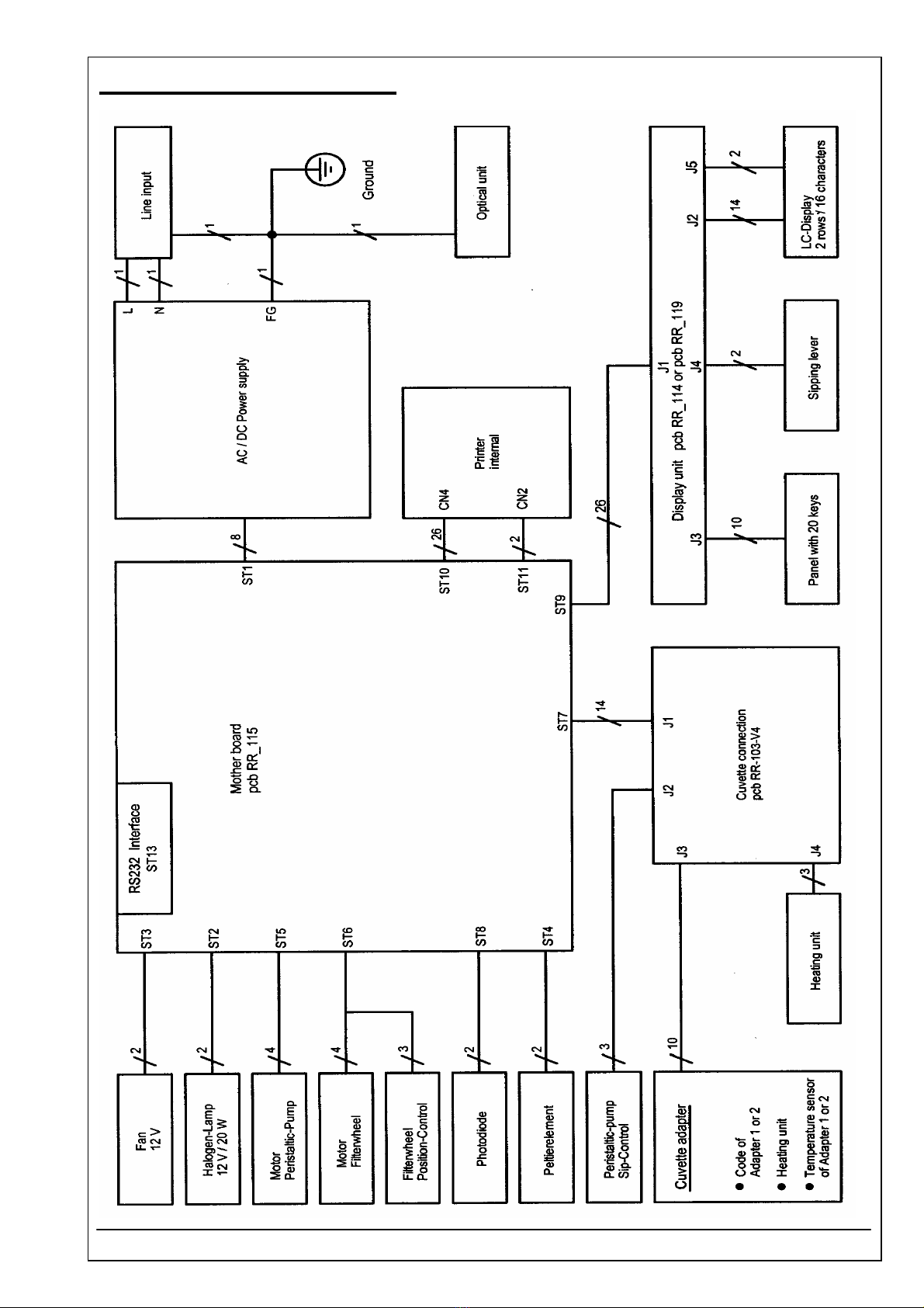
3.1 BLOCK DIAGRAM
RIELE BERLIN Photometer 5010 / V4 3.1.1 11.05.2004

3.2 SHORT INSTRUCTION GUIDE
RIELE BERLIN Photometer 5010 Service 3.2.1 22.08.2003
MODE FUNCTIONS
The mode functions serve for changing definite basic settings during a course of method. It is not necessary to
exit the method and to change to the level of UTILITY PROGRAMS (OM chapter 8). Also temporary parameters
remain unchanged. Corresponding to these features this group of functions is available only within the repetition
sequence of a course of method (chapter 5.5 – DESCRIPTION OF METHOD COURSES).
Change to the selection level of the mode functions with [MODE].
Selection level of the mode functions: Selecting the desired mode function by
direct selection i.e. input of the number key in question (see table) or by scrolling
through all mode functions with [+] ... [+]. Confirm with [ENTER].
Exit the selection level of the mode functions and change back to the course of
method with [BREAK].
After working off a mode function the return is carried out to the course of method.
MODE FUNCTIONS
Key/-combination
Function Chapter
[MODE] [4]
Parallel printers ON / OFF 5.6
[MODE] [5]
Multi-standard tools 5.10
[MODE] [6]
Pump utilities 5.7
[MODE] [7]
Serial interface utilities 5.8
[MODE] [8]
Changing sample numerator 5.9
MODE FUNCTIONS

3.2 SHORT INSTRUCTION GUIDE
RIELE BERLIN Photometer 5010 Service 3.2.2 22.08.2003
SELECTION OF UTILITY PROGRAMS
Method selection: change to utility program selection with [MODE].
Confirm with [MODE].
Utility program selection: direct selection of required utility program, i.e. input of
concerning identity no. (see table) and confirming with [ENTER], or by scrolling
through all utility programs with [+] ... [+].
Abort of utility program selection and return to program selection with [BREAK].
A utility program can be broken off with [BREAK] at any time with return to the
selection of utility programs.
After working off a utility program automatic return to the selection of utility
programs.
Identity
-No.
Utility Program Descript
ion
in
chapter
1 Dark level adjustment 8.2.1
2 Adjustment of bubble detector 8.2.2
3 Error list 8.2.3
4 Deleting method 8.2.4
5 Language selection 8.2.5
6 Beep ON / OFF 8.2.6
7 Temperature control ON / OFF 8.2.7
8 Temperature calibration 8.2.8
9 AD-Transducer 8.2.9
10 ADC dark current values 8.2.10
11 Display test 8.2.11
12 Printing device configuration 8.2.12
13 Real time clock ON / OFF 8.2.13
14 Filter wheel test 8.2.14
15 Temperature correction single cuvette
adaptor
8.2.15
16 Temperature correction flow-through
adaptor
8.2.16
17 Printing user defined methods 8.2.17
INPUT 1-n/+
UTILITIES
METHOD NO.
INPUT 1-250

3.3 SERVICE TOOLS
RIELE BERLIN Photometer 5010 / V4 3.3.1 19.09.2003
SELECTION OF SERVICE TOOLS
In the service program level there are functions influencing special basic parameters of the instrument.
Because they are allowed to be changed divergent from the work configuration only in exceptions and only by
trained staff, their unintentional selection is protected by a password.
Program selection: Change to service program selection with [MODE].
Confirm with [LF].
Enter password [13467]. Confirm with [ENTER].
The service level will be opened until to the next shutdown of the device.
Service tools selection: Direct selection of desired service tool, i.e. input of
concerning item no. (see table) and confirming with [ENTER], or by scrolling
through all service tools with [+] ... [+].
Abort of service tool selection and change back to program selection with
[BREAK].
A service tool can be broken off with [BREAK] at an any time. Then a change is
carried out back to the selection of service tools.
After working off a service tool the return is carried out to the selection of service
tools.
Item no. Service tool Description
in chapter
1 System initialization S1
2 Free methods initialization S2
3 Parameter initialization S3
4 Serial number S4
5 Boost mode S5
6 Filter select S6
7 Automatic Result S7
8 Temperature functions S8
9 Block Code Character from
method
S9
10 Analog-digital converter
correction
S10
11 Voltages S11
12 Reduction of lamp voltage S12
13 Attribut of PCB layout S13
14 Patients data initialization S14
METHOD NO.
INPUT 1-250
PASSWORD 13467
SERVICE TOOLS
INPUT 1-n/+
SERVICE TOOLS
3.3 SERVICE TOOLS
RIELE BERLIN Photometer 5010 / V4 3.3.2 19.09.2003
DESCRIPTION OF SERVICE TOOLS
S1 System initialization
With this function the default parameters will be set.
Start menu by [MODE] [LF] [1]:
Confirm with [ENTER].
Following settings are then typed over in the battery powered RAM. They remain
active, even after switching the instrument off/on, until they are specifically
changed. This action ends with a long beep and a print-out of the program
release.
Beeper ON
Printer internal ON
Printer external OFF
Real time clock ON
Boost mode up to 390 nm
Language english
Analog-digital converter correction 75
Temperature control: Correction values 3000
EDP OFF
EDP protocol STX/ETX/BCC
Baud rate 9600 bps
Resulting factors of methods based on standard cleared
Error list cleared
Laboratory name not affected
User name not affected
Patients data not affected
Bubble detector ON
S2 Free methods initialization
Attention! With this function all methods edited by the user are deleted without call-back. In the case of doubt
these methods should be checked before: Scroll through all methods with the method editor and note them
down for an optional later new programming.
Start menu by [MODE] [LF] [2]:
Confirm with [ENTER].
This action ends with a long beep.
SYSTEM INIT. S1
SERVICE TOOLS
FR.METH.INIT. S2
SERVICE TOOLS

3.3 SERVICE TOOLS
RIELE BERLIN Photometer 5010 / V4 3.3.3 19.09.2003
S3 Parameter initialization
Attention! The extended memory for the parameters of all nonlinear methods is deleted by this function without
call-back and the corresponding user defined methods become useless.
Start menu by [MODE] [LF] [3]:
Confirm with [ENTER].
This action ends with a beep.
S4 Serial number
Display of the current serial number. A new number can be entered with max. five digits.
Start menu by [MODE] [LF] [4]:
Confirm with [ENTER].
Confirm the input with [ENTER].
S5 Boost mode
To improve the low light gain at small wavelengths, the measurement time is extended when operating below
a definite wavelength. This definite wavelength will be displayed for approx. 2 sec. when starting this service
program. The default value is 390 nm.
Start menu by [MODE] [LF] [5]:
Confirm with [ENTER].
Enter [0] = BOOST OFF or a value between 300 and 900 as definite wavelength
in nanometers, below which the boost mode is activated. Finally confirm the input
with [ENTER].
S6 Filter select
The assignment of filter positions can be made.
Start menu by [MODE] [LF] [6]:
Confirm with [ENTER].
Select filter position by numeric key. Confirm the input with [ENTER].
Enter new wavelength by numeric key. Confirm the input with [ENTER].
Finish the operation with [BREAK].
PARAM. INIT. S3
SERVICE TOOLS
SERIAL NO. S4
SERVICE TOOLS
BOOST ON/OFF S5
SERVICE TOOLS
FILTERSELECT S6
SERVICE TOOLS

3.3 SERVICE TOOLS
RIELE BERLIN Photometer 5010 / V4 3.3.4 19.09.2003
S7 Automatic Result
With this service program a continuous measuring mode based on calculation procedure 1 (endpoint with
factor) is possible. After the input of wavelength, factor and delay-time and after measuring blank the con-
tinuous measuring mode is started.
Start menu by [MODE] [LF] [7]:
Confirm with [ENTER].
This mode is active until [BREAK] is pressed (and held for a while).
S8 Temperature functions
A sub menu with eight items for temperature functions is called.
Start menu by [MODE] [LF] [8]:
Confirm with [ENTER].
Direct selection of desired service tool, i.e. input of concerning item no. and
confirming with [ENTER], or by scrolling through all temperature functions
with [+] ... [+].
Item no. Service tool Description
in chapter
1 Temperature regulation on / off S8.1
2 Temperature value of standard
cuvette adaptor
S8.2
3 Temperature value of
flowthrough cuvette adaptor
S8.3
4 Temperature calibration S8.4
5 Temperature required / actual S8.5
6 Temperature Analog-Digital-
Converter
S8.6
AUTO. RESULT S7
SERVICE TOOLS
TEMP. FUNCT. S8
SERVICE TOOLS

3.3 SERVICE TOOLS
RIELE BERLIN Photometer 5010 / V4 3.3.5 19.09.2003
S8.1 Temperature regulation on / off
The temperature regulation can be switched on or switched off. In the display the current setting is shown.
Start menu by [1]:
Confirm with [ENTER].
Changing of the setting with the keys [1] = ON or [0] = OFF.
The displayed setting becomes active with [ENTER] and [BREAK].
Select temperature level by [1], [2] or [3] in case of setting ON.
S8.2 Temperature value of standard cuvette adaptor
Display of the current setting. The correction of the temperature regulation is possible by change of the
temperature setting.
Start menu by [2]:
Confirm with [ENTER].
Select temperature level by [1], [2] or [3].
Enter new temperature value and confirm with [ENTER]
or finish operation with [BREAK]. The window shows for example the value 13047
for the temperature level 37 °C.
S8.3 Temperature value of flowthrough cuvette adaptor
Display of the current setting. The correction of the temperature regulation is possible by change of the
temperature setting.
Start menu by [3]:
Confirm with [ENTER].
Select temperature level by [1], [2] or [3].
Enter new temperature value and confirm with [ENTER]
or finish operation with [BREAK]. The window shows for example the value 13047
for the temperature level 37 °C.
TEMP. ON/OFF
INPUT +/E/B
HEATING OFF
1/ON 0/OFF
E-TEMP. VALUE
INPUT +/E/B
HEATING ON
1/25 2/30 3/37
E-TEMP. VALUE
1/25 2/30 3/37
37C VALUE E
13047
D-TEMP. VALUE
INPUT +/E/B
D-TEMP. VALUE
1/25 2/30 3/37
37C VALUE D
13047

3.3 SERVICE TOOLS
RIELE BERLIN Photometer 5010 / V4 3.3.6 19.09.2003
S8.4 Temperature calibration
The correction of the temperature regulation is possible by input of the temperature which is measured in the
cuvette with an external measuring system (only when the temperature regulation is stabilized).
Start menu by [4]:
Confirm with [ENTER].
Confirm with [ENTER].
The display shows the current temperature level at the required value of 37 °C.
Enter the actual temperature value always four-digit in °C e.g. [3] [7] [,] [2] [0]
[ENTER] measured by an external measuring system. The system calculates and
stores the new setting for 37.0 °C and starts working with it at once.
S8.5 Temperature required / actual
The correction of the temperature regulation is possible by input of the temperature which is measured in the
cuvette with an external measuring system (only when the temperature regulation is stabilized).
Start menu by [5]:
Confirm with [ENTER].
Confirm with [ENTER].
The display shows in the second line the required value (e.g. 14270),
the actual value (e.g. 14275) and the type of cuvette adapter (e.g. D).
S8.6 Temperature Analog-Digital-Converter
Display of the counter value of the temperature ADC and of the current stability value.
Start menu by [6]:
Confirm with [ENTER].
Confirm with [ENTER].
The display shows in the second line the actual value of the ADC (e.g. 954),
and the stability value S (e.g. 0).
TEMP. CALIBR.
INPUT +/E/B
INPUT DEGREE C
37C 37.20
TEMP. REQU / ACT
INPUT +/E/B
TEMP. REQU / ACT
14270 14275 D
TEMP. ADC
INPUT +/E/B
TEMP. ADC
ADC 954 S 0

3.3 SERVICE TOOLS
RIELE BERLIN Photometer 5010 / V4 3.3.7 19.09.2003
S9 Block Code Character from method
To check the correct storing of a user-defined method, the special test byte BCC concerning the data in the
memory is used. With this service program the BCC of a method can be determined.
Start menu by [MODE] [LF] [9]:
Confirm with [ENTER].
The number of the concerning method must be entered and confirmed with
[ENTER]. Then the BCC is displayed in the decimal form.
Press [ENTER] and select another number of a method.
Press [BREAK] for exit.
S10 Analog-digital converter correction
Display of the actual correction value of the analog-digital converter (photometric measuring system). In the
delivering condition the value is 75.
Start menu by [MODE] [LF] [10]:
Confirm with [ENTER].
By input of a correction value between 0 and 255 and confirming with [ENTER]
measurements seeming too low can be increased a little bit. This correction
recognizably affects only at high results (~ 2 Absorbance).
S11 Voltages
Display of the actual voltages on the pcb.
Start menu by [MODE] [LF] [11]:
Confirm with [ENTER].
Confirm with [ENTER].
The display shows the actual voltages of
+ 12 VDC of halogen lamp / fan (1. line left)
+ 12 VDC and - 12 VDC of analogic circuits (1. line right)
+ 5 VDC of VCC (2. line left)
+ 15 VDC of power supply (2. line middle)
VDC voltage of Peltier element (2. line right)
BCC FROM METH.S9
SERVICE TOOLS
ADC CORRECT.S10
SERVICE TOOLS
VOLTAGES S11
SERVICE TOOLS
12.03 12+0.07
-4.93 14.75 0.01

3.3 SERVICE TOOLS
RIELE BERLIN Photometer 5010 / V4 3.3.8 19.09.2003
S12 Reduction of lamp voltage
The voltage + 12 VDC of halogen lamp can be reduced for lamp adjustment in vertical direction.
Start menu by [MODE] [LF] [12]:
Confirm with [ENTER].
Confirm with [ENTER]. Adjust lamp in vertical direction.
Press [BREAK] for exit.
S13 Attribut of PCB layout
The attribut of the PCB layout can be read and set. Software applications may be dependent on this attribut.
The attribut is labeled on the PCB RR_111 near plug ST13 (RS232C interface).
Start menu by [MODE] [LF] [13]:
Confirm with [ENTER].
Confirm with [ENTER].
In the second line the display shows the version of PCB layout, e.g. the value „c“.
Change the value by [+] in case of a deviation and confirm the input by [ENTER].
Leave the window by [BREAK] in case of no change.
S14 Patients data initialization
The memory of patients data mangement is cleared completely.
Start menu by [MODE] [LF] [14]:
The memory is cleared by confirming with [ENTER].
This action ends with a long beep.
PCB LAYOUT S13
SERVICE TOOLS
DEL.PATIENTS S14
SERVICE TOOLS
LAMP DOWN S12
SERVICE TOOLS
PCB LAYOUT S13
c +EB
Table of contents
Other Riele Measuring Instrument manuals


Popular Measuring Instrument manuals by other brands

Power Test
Power Test Superflow SF-Black Widow Operator's manual

UEi
UEi HUB2 instruction manual

Sensia
Sensia CALDON SVM 289Ci user manual

Shodex
Shodex CLNpak EV2000AC-12F Operation manual

Pres Block
Pres Block AFNOR NF S 90-116 Use and maintenance handbook

Compressed Air Alliance
Compressed Air Alliance POM100 user manual

R.M. Young
R.M. Young 05305V instructions

YOKOGAWA
YOKOGAWA ADMAG TI Series Read me first

water & more
water & more Aquameter Installation and operating instructions

weschler instruments
weschler instruments Power Series Plus user manual

Endress+Hauser
Endress+Hauser Liquicap M FTI51 operating instructions

Omega
Omega HHTQ35 user manual


